


Chapter 7 Surgical Extraction of Impacted Teeth |
155 |
7.8
Extraction of Impacted Maxillary Teeth
7.8.1
Impacted Third Molar
Removal of an impacted maxillary third molar is difficult, because of insufficient visualization of the area and limited access. Furthermore, other factors (reduced aperture of the mouth, close proximity of the impacted tooth to the maxillary sinus, etc.) may make the surgical procedure even more difficult.
Classification. Impaction of the maxillary third molar (according to Archer 1975) may be classified as: mesioangular, distoangular, vertical, horizontal, buccoangular, linguoangular, or inverted (Fig. 7.100). The tooth usually presents with a mesial or distal inclination, with the occlusal surface positioned buccally.
Impacted maxillary third molars may also be classified (Archer 1975), according to the depth of impaction compared to the second molar, into three categories:
Class A: The occlusal surface of the impacted tooth is at approximately the same level as the occlusal surface of the second molar (Fig. 7.101 a).
Class B: The occlusal surface of the impacted tooth is at the middle of the crown of the adjacent second molar (Fig. 7.101 b).
Class C: The occlusal surface of the crown of the impacted tooth is below the cervical line of the adjacent molar or even deeper, contiguously or even above its roots (Figs. 7.101 c–e).
Impacted teeth belonging to the third category are very difficult cases, because their extraction entails the removal of large amounts of bone, limited access, and the risk of displacing the impacted tooth into the maxillary sinus (Fig. 7.102).
Fig. 7.100. Classification of impaction of maxillary third molars according to Archer (1975). (1 Mesioangular,
2 distoangular, 3 vertical, 4 horizontal,
5 buccoangular, 6 linguoangular,
7 inverted)
Fig. 7.101 a–e. Classification of impacted maxillary third molars according to Archer (1975), depending on the depth of impaction compared to the adjacent second molar

156 F. D. Fragiskos
Fig. 7.102 a, b. Maxillary third molars with deep, complete bone impaction. Their removal is considered difficult, because of the closeness to the maxillary sinus and insufficient visualization of the area
Types of Flaps. The types of flaps used are triangular and horizontal:
Triangular flap:
The incision for creating the flap begins at the maxillary tuberosity and extends as far as the distal aspect of the second molar, continuing obliquely upwards and anteriorly (vertical incision) to the
vestibular fold (Fig. 7.103). In rare cases, when impaction is deep and a satisfactory surgical field is necessary or when the impacted tooth covers the roots of the second molar buccally, then the vertical incision may be made at the distal aspect of the first molar (Fig. 7.104).
Incisions and Types of Flaps for Extraction of Impacted Third Molar
Fig. 7.103 a, b.
Diagrammatic illustrations showing the triangular incision (a) and reflection of the flap (b), indicated in certain cases of extraction of impacted maxillary third molars
Fig. 7.104 a, b. Variation of the triangular incision and flap shown in Fig. 7.103 (the vertical incision extends as far as the distal aspect of the first molar). The mesial extension
of the incision is necessary due to the position of the third molar compared to the second molar

Chapter 7 Surgical Extraction of Impacted Teeth |
157 |
Fig. 7.105 a, b. Diagrammatic illustrations showing the horizontal incision (a) and envelope flap (b), for removal of impacted maxillary third molars
Horizontal (envelope) flap:
The incision for creation of this flap also begins at the maxillary tuberosity and extends as far as the distal aspect of the second molar, continuing buccally along the cervical lines of the last two teeth, and ending at the mesial aspect of the first molar (Fig. 7.105).
Removal of Bone. Often, after reflection of the flap, part of the crown of the impacted tooth is visible or there is bone protuberance over the crown. Because the bone in this case is thin and spongy, it may be removed from the buccal surface using a sharp instrument. If the buccal bone is dense and thick, then its removal is achieved using a surgical bur.
7.8.1.1
Extraction of Impacted Third Molar
The procedure for removing the impacted third molar
(Fig. 7.106) is as follows.
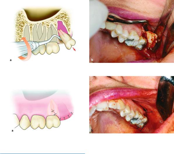
After making a triangular incision (Fig. 7.107), the mucoperiosteal flap is reflected (Fig. 7.108) and the buccal bone is then removed until the entire crown of the impacted tooth and part of its roots are exposed.
Because extraction of the tooth in segments is not indicated, sufficient space must be created around its crown to be able to luxate the tooth. Thus, using a straight or double-angled elevator on the mesial aspect of the tooth, always buccally, the tooth is luxated carefully,posteriorly,outwardsanddownwards(Figs. 7.109, 7.110). Care of the wound and suturing are performed in the same way as described for all other cases of impacted teeth (Fig. 7.111).
Fig. 7.106 a, b. a Radiograph showing a maxillary third molar with distoangular impaction. b Clinical photograph of the case shown in a
158 F. D. Fragiskos
Fig. 7.107 a, b. Triangular incision completed. a Diagrammatic illustration. b Clinical photograph
Fig. 7.108 a, b. Reflection of the flap and exposure of the crown of the impacted tooth. Placement of the broad end of the periosteal elevator in the posterior position is indicated
to protect the tooth from becoming accidentally displaced into the infratemporal fossa or into soft tissues. a Diagrammatic illustration. b Clinical photograph
Fig. 7.109 a, b. Luxation of the impacted tooth using double-angled elevator. Extraction movements depend largely upon the relationship between the tooth and the maxillary sinus. a Diagrammatic illustration. b Clinical photograph
Chapter 7 Surgical Extraction of Impacted Teeth |
159 |
Fig. 7.110 a, b. Final luxation of the tooth. a Diagrammatic illustration. b Clinical photograph
Fig. 7.111 a, b. Surgical field after placement of sutures. a Diagrammatic illustration. b Clinical photograph
7.8.2
Impacted Canines
Impacted maxillary canines are quite common, and approximately 12%–15% of the population present with impacted canines. They are localized palatally more often than labially.
Even though positions vary, the impacted canine presents five basic localizations (contralateral or ipsilateral and deep in the bone) as follows:
1.Palatal localization
2.Palatal localization of crown and labial localization of root
3.Labial localization of crown and palatal localization of root
4.Labial localization
5.Ectopic positions
In young people aged 20 years or slightly older, impacted maxillary canines may be correctly aligned in
the dental arch after surgical exposure and orthodontic treatment. In older patients, especially after the age of 30 years, the above procedure is not a method of choice, because the risk of failure is greater. In such cases, surgical removal is preferred, if deemed necessary of course.
The technique for removing impacted canines depends on the position of impaction (palatal or labial), the relationship of the impacted tooth to adjacent teeth, as well as the inclination of its crown. These factors should be assessed before planning the surgical procedure.
The localization of impacted canines is achieved using various radiographic techniques together with careful clinical examination. The most commonly used intraoral projections are occlusal projections, periapical radiographs and panoramic radiographs, while the technique employed for exact localization of the labial or palatal position of the impacted tooth is based on the tube shift principle, as described in
Chap. 2. As far as the clinical examination is con-
160 F. D. Fragiskos
cerned, a palpable protuberance of the area designates the position of the tooth quite accurately. Based on the data from the clinical and radiographic examination, the surgical removal of impacted canines may be performed in three ways: with the labial approach, the palatal approach or a combination of the two.
7.8.2.1
Extraction Using Labial Approach
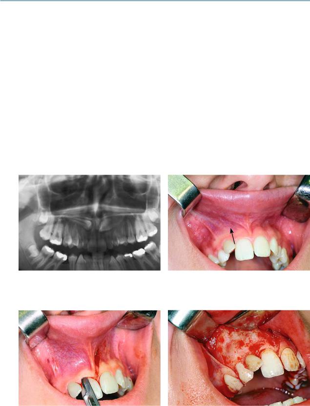
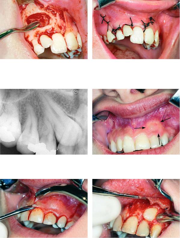
If the impacted tooth is localized labially and is entirely covered by bone (Figs. 7.112, 7.113), the procedure for its removal is as follows. First a trapezoidal incision is created and the mucoperiosteum is then re-
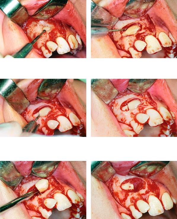
flected (Figs. 7.114, 7.115). The bone covering the tooth is removed using a round bur, with a steady stream of saline solution, until the entire crown of the tooth and part of the root are exposed (Figs. 7.116, 7.117). A groove is then created at the cervical line using a fissure bur, in order to separate the crown from the root
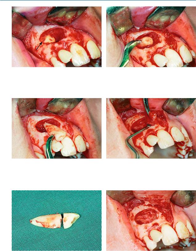
(Figs. 7.118, 7.119). Separation is achieved using a straight elevator, which is placed in the groove. Upon rotation, the instrument separates the tooth into two segments. The crown is removed first and the root is then luxated, after creating a purchase point on the surface of the root for placement of the tip of the elevator blade (Figs. 7.120–7.126). After smoothing the bone, the area is thoroughly irrigated with saline solu-
Fig. 7.112. Radiograph showing impacted maxillary canines. Right canine is located labially while left canine is located palatally
Fig. 7.113. Clinical photograph of the labial area where the right canine of the case shown in Fig. 7.112 is localized
Fig. 7.114. Surgical procedure for removal of right impact- Fig. 7.115. Reflection of the mucoperiosteal flap ed canine. A trapezoidal incision is created buccally
Chapter 7 Surgical Extraction of Impacted Teeth |
161 |
tion, and the wound is sutured (Figs. 7.127–7.129). When the impacted tooth is not entirely covered by bone, but the crown of the tooth is covered by overly-
ing soft tissues, removal of the tooth is easier, since it does not have to be sectioned into two pieces
(Figs. 7.130–7.138).
Fig. 7.116. A round bur is used to remove the bone covering the crown of the tooth
Fig. 7.118. Sectioning of the crown–root at the cervical line of the tooth, using a fissure bur
Fig. 7.117. Complete exposure of the crown of the tooth and part of the root
Fig. 7.119. Tooth after sectioning
Fig. 7.120. Removal of the crown of the impacted tooth Fig. 7.121. Root of the tooth after removal of the crown using a straight elevator
162 F. D. Fragiskos
Fig. 7.122. Purchase point created on the root for place- |
Fig. 7.123. Luxation of the root using a curved Chompret |
ment of the elevator blade |
elevator |
Fig. 7.124. Final step of root extraction |
Fig. 7.125. Removal of follicle using a hemostat and peri- |
|
apical curette |
Fig. 7.126. The two segments of tooth after removal |
Fig. 7.127. Surgical field after removal of the tooth |
Chapter 7 Surgical Extraction of Impacted Teeth |
163 |
Fig. 7.128. Smoothing of the bone edges of the wound us- Fig. 7.129. Surgical field after suturing ing a bone file
Extraction of Impacted Canine with Partial Bone Impaction
Fig. 7.130. Radiograph showing an impacted maxillary canine with a labial localization
Fig. 7.131. Clinical photograph of the area of impaction. The ischemic protuberance, shown by arrows, indicates the position of the crown of the impacted tooth
Fig. 7.132. Trapezoidal incision and reflection of the mucoperiosteal flap
Fig. 7.133. Reflection of the flap and exposure of the crown of the impacted tooth, which was not covered by bone
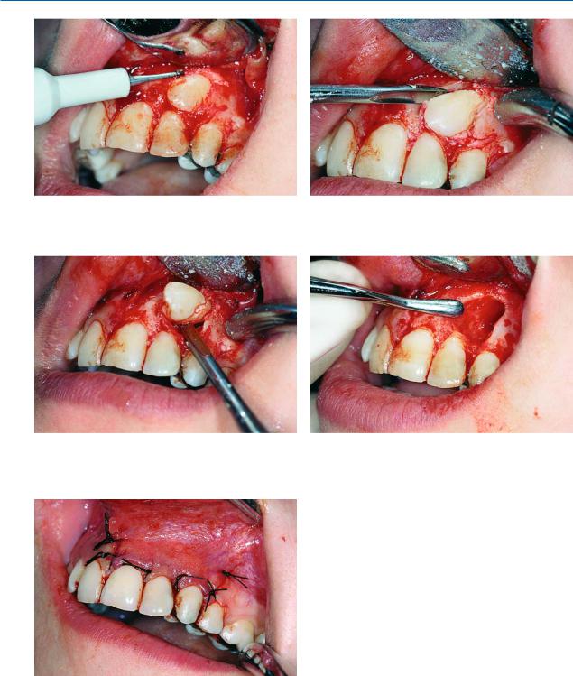
164 F. D. Fragiskos
Fig. 7.134. Creation of a groove between the crown and bone, allowing for positioning of the elevator
Fig. 7.136. Removal of the tooth in a mesial, upward and outward direction
Fig. 7.138. Surgical field after placement of sutures
Fig. 7.135. Placement of the straight elevator in a groove created for tooth luxation
Fig. 7.137. Smoothing of bone edges of the wound using a bone file
7.8.2.2
Extraction Using Palatal Approach
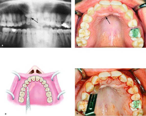
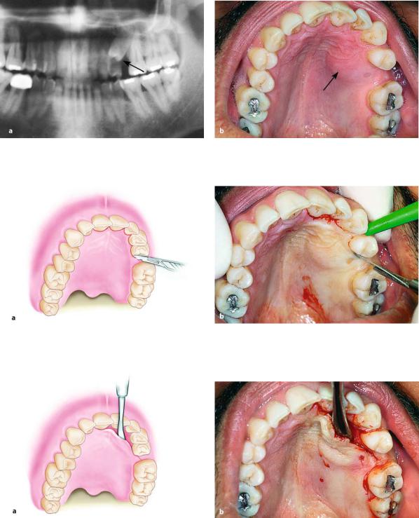
When the impacted tooth is positioned palatally (Fig. 7.139), the approach is achieved using a bilateral palatal flap. The incision for creation of the flap begins at the first or second ipsilateral premolar and, after continuing along the cervical lines of the teeth, ends at the first premolar on the contralateral side (Fig. 7.140).
After careful reflection of the mucoperiosteum, part of the crown of the tooth may be exposed, or the entire crown may be covered by bone, resulting in protuberance at that site (Fig. 7.141). Either way, enough
Chapter 7 Surgical Extraction of Impacted Teeth |
165 |
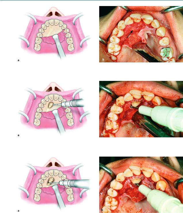
bone must be removed to expose the entire crown, so that the tooth may be extracted using forceps or an elevator (Fig. 7.142). If the tip of the crown is positioned between the roots of the lateral and central incisors, there is a risk of injuring their roots during the exposure attempt. That is why extraction of the canine must be achieved using the technique of separating the crown from the root. More specifically, a groove is created on the cervical line of the tooth using a fissure bur (Fig. 7.143) and, after placing the elevator blade in the
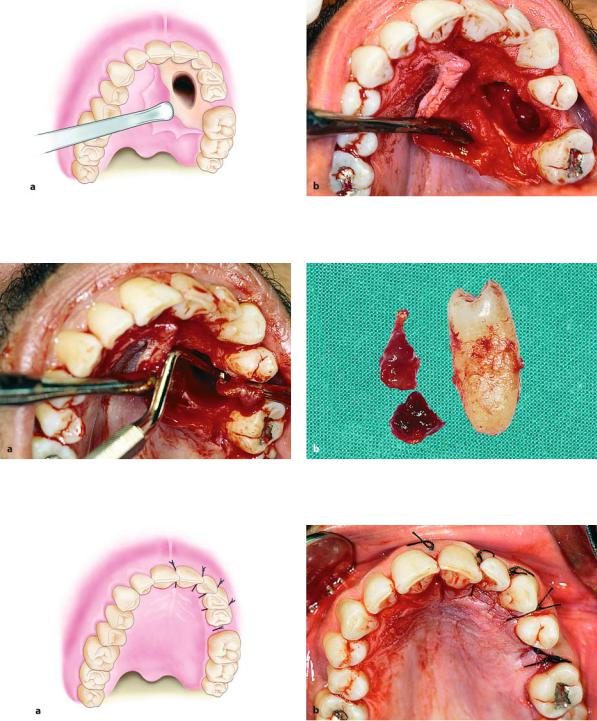
groove created, the instrument is rotated until the crown is separated from the root (Fig. 7.144). The crown is then removed, and, after using the round bur to create a purchase point on the root for placement of the angled elevator’s tip, the root is elevated from its bed (Figs. 7.145, 7.146). After this procedure, the bone edges are smoothed, and the area is thoroughly irrigated with saline solution, while the flap is repositionedandsuturedwithinterruptedsutures(Figs. 7.147, 7.148).
Fig. 7.139 a, b. a Radiograph showing an impacted maxillary canine with palatal localization. b Clinical photograph of the area of impaction
Fig. 7.140 a, b. Palatal incision along the cervical lines of the teeth. a Diagrammatic illustration. b Clinical photograph
166 F. D. Fragiskos
Fig. 7.141 a, b. Diagrammatic illustration (a) and clinical photograph (b) after reflection of the flap. Arrow points to the protuberance of bone, which indicates the position of the crown of the impacted tooth
Fig. 7.142 a, b. Removal of bone using a round bur, to expose the crown of an impacted tooth. a Diagrammatic illustration. b Clinical photograph
Fig. 7.143 a, b. Sectioning of an impacted tooth at the cervical line and separation of the crown from the root. a Diagrammatic illustration. b Clinical photograph

Chapter 7 Surgical Extraction of Impacted Teeth |
167 |
Fig. 7.144 a, b. Placement of the straight elevator in the groove created to separate the crown from the root and removal of the crown. a Diagrammatic illustration. b Clinical photograph
Fig. 7.145 a, b. Removal of root from its position in the bone using an angled elevator. a Diagrammatic illustration. b Clinical photograph
Fig. 7.146 a, b. Surgical field after removal of the impacted tooth. a Diagrammatic illustration. b Clinical photograph
168 F. D. Fragiskos
Fig. 7.147 a, b. a The two segments of tooth after removal. b The flap is repositioned in its initial position and pressure is applied to the area with the index finger for a few seconds
Fig. 7.148 a, b. Surgical field after suturing. a Diagrammatic illustration. b Clinical photograph
7.8.3
Impacted Premolar with Palatal Position
When an impacted premolar is localized palatally
(Fig. 7.149), the surgical approach involves creating a palatal flap. The incision begins at the region of the central incisor and extends along the cervical lines of the teeth, ending at the distal aspect of the first premo-
lar (Fig. 7.150). After creation of the flap, the bone covering the impacted tooth is removed using a round bur, until the entire crown is exposed (Figs. 7.151,
7.152). Afterwards, a groove is created around the tooth using a fissure bur, creating room to facilitate its luxation. The blade of the straight elevator is placed in this groove at the mesial and distal aspects of the tooth, luxating it from its socket (Figs. 7.153–7.157).
Chapter 7 Surgical Extraction of Impacted Teeth |
169 |
Fig. 7.149 a, b. a Radiograph showing impacted maxillary premolar with a palatal localization. b Clinical photograph of the area of impaction
Fig. 7.150 a, b. Palatal incision along the cervical lines of the teeth using a scalpel with no. 15 blade. a Diagrammatic illustration. b Clinical photograph
Fig. 7.151 a, b. Reflection of the mucoperiosteal flap. a Diagrammatic illustration. b Clinical photograph

170 F. D. Fragiskos
Fig. 7.152. Removal of bone to expose the crown of the impacted tooth. a Diagrammatic illustration. b Clinical photograph
Fig. 7.153 a, b. a Groove created around the crown of the tooth to facilitate its luxation. b Luxation of the impacted tooth using straight elevator
Fig. 7.154 a, b. Final luxation of tooth. a Diagrammatic illustration. b Clinical photograph
Chapter 7 Surgical Extraction of Impacted Teeth |
171 |
Fig. 7.155 a, b. Surgical field after removal of the impacted tooth. a Diagrammatic illustration. b Clinical photograph
Fig. 7.156 a, b. a Removal of the follicle using a hemostat and periapical curette. b Tooth and follicle after removal
Fig. 7.157 a, b. Surgical field after placement of sutures. a Diagrammatic illustration. b Clinical photograph

172 F. D. Fragiskos
7.8.4
Ectopic Impacted Canine
The presence of ectopic impacted teeth is relatively rare. Ectopic teeth are usually localized in the following places: underneath permanent teeth, near the angle of the mandible, inside the ramus, near the mandibular notch, the coronoid process, the maxillary tuberosity, the wall of the maxillary sinus, the nasal cavity and, rarely, near the orbit.
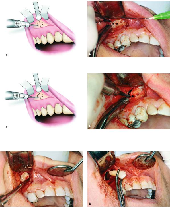
The case presented involves an impacted canine, localized in the anterior wall of the maxillary sinus (Fig. 7.158). The procedure for removing such impacted teeth is usually as follows. First a horizontal incision is made in the region of the canine fossa, from the lateral incisor as far as the first molar (Fig. 7.159).
The mucoperiosteum is then reflected and the bone of the anterior wall of the maxillary sinus is exposed (Fig. 7.160). Holes are drilled through the bone using a small round bur where the impacted tooth is estimated to be, and these holes are then joined together
Fig. 7.158. Radiograph showing impacted canine with a labial localization, which is in contact with the anterior wall of the maxillary sinus
Fig. 7.159. Incision in canine fossa region, for sinus trephination using the Caldwell–Luc approach
Fig. 7.160 a, b. Reflection of the mucoperiosteal flap and exposure of the anterior wall of maxillary sinus. a Diagrammatic illustration. b Clinical photograph
Chapter 7 Surgical Extraction of Impacted Teeth |
173 |
(Figs. 7.161, 7.162). After removal of the bone surface, the impacted tooth is exposed and carefully luxated outwards (Fig. 7.163). After smoothing the bone edges of the wound, the area is irrigated thoroughly with sa-
line solution and any foreign matter that has entered the maxillary sinus is aspirated with the suction tip. Finally, the flap is sutured (Fig. 7.164), and nasal decongestants are prescribed.
Fig. 7.161 a, b. Holes drilled through the bone surface defining the border of bone to be removed
Fig. 7.162 a, b. Connecting holes to remove the bone covering the impacted tooth. a Diagrammatic illustration. b Clinical photograph
Fig. 7.163 a, b. a Exposure and luxation of the impacted tooth using straight elevator. b Removal of tooth using a hemostat