


22 E. Stefanou
2.1
Radiographic Assessment
Conventional radiographs have coherent limitations, since they depict a three-dimensional object as a twodimensional image, therefore they present a disadvantage in determining the depth of the depicted images.
In order to gather as much information as possible from a radiograph, a dentist must visualize the exact three-dimensional image of the anatomic areas of interest based on one or more of such two-dimensional images (radiographs).
The radiographic detection technique is basically used to locate:
ΟForeign bodies, provided they are radiopaque.
ΟRoot remnants and other tooth fragments that may have been displaced into the surrounding tissues.
ΟImpacted teeth and supernumerary teeth.
ΟSoft tissue calcifications.
Ο Fractures of the jaw.
ΟExpansion of the buccal or lingual wall of the jaw.
ΟRelationship of impacted teeth, roots, etc. to adjacent anatomical structures (nasal cavity, maxillary sinus, and inferior alveolar nerve).
Many times, clinical examination of the patient will reveal an impacted tooth, which is confirmed by a radiograph. An impacted tooth may also be discovered by chance on a radiograph.
Determining the position of impacted teeth on a horizontal level is important for the diagnosis and treatment plan, which entails either the extraction of the impacted tooth or its alignment in the arch with orthodontic therapy.
The impacted teeth that create the most localization problems are canines of the maxilla, which are often found palatally.
The techniques used to determine the position of the tooth are:
ΟMagnification technique.
ΟTwo radiographs with different reference planes
(right-angle or cross-section technique).
ΟTube shift principle or parallax.
ΟVertical transversal tomography of the jaw.
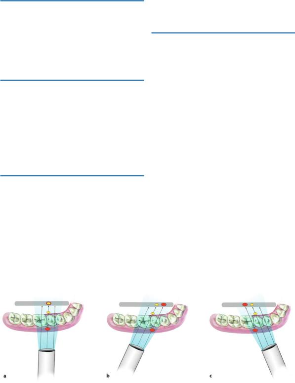
Fig. 2.1a–c. a Positioning x-ray tube and x-ray film for taking a radiograph. b The impacted tooth, which is found buccally and further away from the film compared to the tooth in the dentition, is projected magnified. c The impacted tooth, which is found palatally and closer to the film compared to the tooth in the dentition, is projected as being a smaller size
Chapter 2 Radiographic Examination in Oral Surgery |
23 |
2.2
Magnification Technique
This is based on the principle that, given a specific distance between an x-ray film and x-ray tube, the objects further away from the reference structures will be magnified to a greater degree compared to those that are closer to the film (Fig. 2.1a–c).
2.3
Two Radiographs
with Different Reference Planes
Localization with this method is based on taking two radiographs at right angles to each other or two radiographs with different reference planes, not quite at a right angle, but almost. The position of the foreign body in relation to the three dimensions is determined this way.
2.4
Tube Shift Principle
This is based on the following principle: when an observer looks at two objects and starts moving, they will notice that the object further away seems to move in the same direction, while the object closer to the observer seems to move in the opposite direction. Based on this principle, when we have two radiographs with different tube head positions, the impacted tooth will seem to move in the same direction as the tube head
when it is found palatally or lingually, and in the opposite direction compared to the tube head when it is found buccally (Fig. 2.2).
2.5
Vertical Transversal Tomography of the Jaw
This method provides transversal sections or slices of the jaw at the point of interest, thus determining the position of the impacted tooth easily, in relation to the rest of the teeth in the dentition (Fig. 2.3a,b). Apart from axial (computed) tomography, vertical transversal tomography of the jaw is the only means of obtaining detailed information concerning the size and shape of the mandibular canal and its buccolingual relation to the impacted mandibular tooth. Computed axial tomography for the localization of impacted teeth should be used only if there is no other solution; in other words, rarely, and in exceptional cases, due to the very high doses the patient receives.
The magnification technique is unreliable, with a failure rate of 10%; therefore, its use must be indicative only. The other techniques may be used safely.
The combinations that may be used for radiographs with different reference planes are:
ΟLateral cephalometric radiograph – anteroposterior cephalometric radiograph (Fig. 2.4 a,b).
ΟTrue occlusal radiograph – periapical radiograph (Fig. 2.5 a,b).
ΟTrue occlusal radiograph – panoramic radiograph (Fig. 2.6 a,b).
ΟPanoramic radiograph – lateral cephalometric radiograph (Fig. 2.7a,b).
Fig. 2.2a–c. Diagrammatic illustration of the radiographic method of localizing the buccal or lingual position of impacted teeth. Tooth movement depends on the proximal or distal shifting of the x-ray beam with regard to the initial
position of the radiograph (homologous movement: palatal or lingual position, heterologous movement: buccal position)
24 E. Stefanou
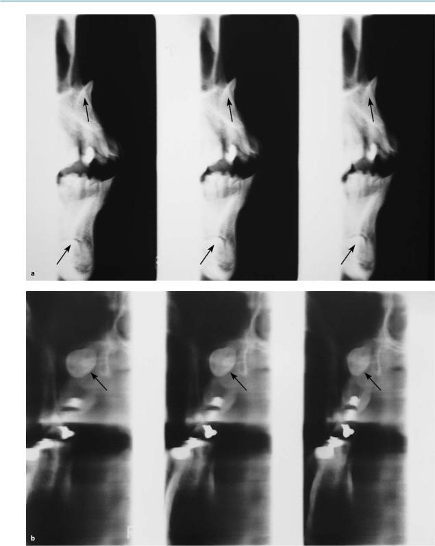
Fig. 2.3 a,b. a Vertical transversal tomography showing the buccal position of an impacted central incisor of the maxilla, as well as the position of the impacted canine of
the mandible beneath and buccal to the roots of the anterior teeth. b Vertical transversal tomography, showing an impacted third molar buccal to the roots of the second molar
Chapter 2 Radiographic Examination in Oral Surgery |
25 |
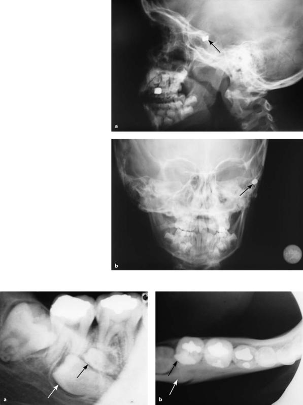
Fig. 2.4 a,b. a Lateral cephalometric radiograph showing a foreign body, whose position is determined on a sagittal and vertical plane. b Anteroposterior cephalometric radiograph on which a foreign body is located on a median and vertical plane
Fig. 2.5 a,b. a Periapical radiograph showing two impacted teeth (premolar and supernumerary). b True occlusal radiograph of the same area, showing the buccal position of the
impacted premolar and the position of the supernumerary microdont between the impacted tooth and the crown of the second molar

26 E. Stefanou
Fig. 2.6a,b. a Panoramic radiograph showing radiopaque areas in the left side of the body of the mandible. b True occlusal radiograph of the mandible of the same case. The
radiopacities are located lingually, in the floor of the mouth. These are sialoliths of the duct of the submandibular gland
Fig. 2.7 a,b. a Panoramic radiograph showing two impacted teeth in the maxilla and mandible. b Lateral cephalometric radiograph of the same case. The impacted teeth are found buccal to the anterior teeth, in the respective areas
Fig. 2.8 a,b. a Periapical radiograph of the anterior maxilla. Two impacted supernumerary teeth (normal projection) are observed. b Periapical radiograph of the same area, with shifting of the tube to the right of the patient. The impacted teeth seem to move in the same direction as the tube, with the left central incisor used as the reference point. This means that the position of the impacted teeth is palatal

Chapter 2 Radiographic Examination in Oral Surgery |
27 |
Fig. 2.9 a,b. a Periapical radiograph of the right maxilla, showing impacted canine. b Occlusal radiograph of the same area, showing shifting of the impacted tooth upwards with respect to the root of the lateral incisor (heterologous shifting: buccal location of tooth)
Fig. 2.10 a,b. a Panoramic radiograph showing radiopaque area at the root tip of the lateral incisor of the lower left jaw. b Periapical radiograph of the same area. The position of the lesion does not seem to change with respect to the root tip of
The following combinations may be used with radiographs applying the tube shift principle:
ΟTwo periapical radiographs with different angles
(Fig. 2.8 a,b).
ΟPeriapical radiograph – occlusal radiograph (Fig. 2.9 a,b).
ΟPeriapical radiograph – panoramic radiograph
(Fig. 2.10 a,b).
ΟOcclusal radiograph – panoramic radiograph (Fig. 2.11 a,b).
the lateral incisor. The fact that the lesion does not seem to shift means that it is found exactly underneath the root tip of that particular tooth
In order to be able to detect the position of the tooth using the tube shift principle, it is necessary to know the radiograph techniques well, so that combinations of the tube shift technique and the illusory shift of the impacted tooth can be interpreted (Fig. 2.12 a–c). Also, the greater the distance of the impacted teeth from the dentition, the greater the apparent shift in position.
As far as localization is concerned, it is important to use any available existing radiographs, to avoid purposeless irradiation of the patient. That way, together with the radiograph confirming the existence of the impacted tooth, only one more radiograph is required to show the localization of the impacted tooth.