


Chapter 7 Surgical Extraction of Impacted Teeth |
125 |
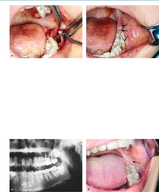
Fig. 7.13 a–c. a Extensive resorption of the roots of maxillary and mandibular second molars due to impacted third molars. Tooth 17 was also removed during the attempt to extract tooth 18, because preservation of the tooth in the dental arch was deemed impossible. b Maxillary second molar (shown in a) after its removal, showing resorption of the distal root. c Complete resorption of the root of the right lateral incisor due to an impacted maxillary canine
destroy the tooth (Figs. 7.12, 7.13 a, b). The resorption of roots may also be observed in other areas of the dental arch and may involve dental surfaces other than those mentioned above (Fig. 7.13 c).
Having mentioned the undesirable situations that are associated with impacted teeth, and given the fact that no one can guarantee that an asymptomatic impacted tooth will not create problems in the future, the choice of removing or preserving the impacted tooth must be made after considering all the possibilities.
7.5
Appropriate Timing for Removal of Impacted Teeth
If the impacted tooth is to be removed, the most suitable time to do so is when the patient is young, thus avoiding the aforementioned complications and undesirable situations that could get worse with time. Also, younger patients generally deal with the overall surgical procedure and stress well, and present fewer complications and faster postsurgical wound healing compared with older patients. Furthermore, it is easier to remove bone from these patients compared to older patients, whose bone is usually dense and hard.
7.6
Steps of Surgical Procedure
The surgical procedure for the extraction of impacted teeth includes the following steps:
1.Incision and reflection of the mucoperiosteal flap
2.Removal of bone to expose the impacted tooth
3.Luxation of the tooth
4.Care of the postsurgical socket and suturing of the wound
The main factors for a successful outcome to the surgical procedure are as follows:
ΟCorrect flap design, which must be based on the clinical and radiographic examination (position of tooth, relationship of roots to anatomic structures, root morphology).
ΟEnsuring the pathway for removal of the impacted tooth, with as little bone removal as possible. This is achieved when the tooth is sectioned and removed in segments, which causes the least trauma possible.
126 F. D. Fragiskos
7.7
Extraction of Impacted Mandibular Teeth
7.7.1
Impacted Third Molar
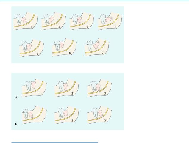
Classification. The impacted mandibular third molar may present with various positions in the bone, and so the technique for its removal is determined by its localization. The classic positions of the tooth, depending on the direction of the crown of the tooth, are (according to Archer 1975; Kruger 1984): mesioangular, distoangular, vertical, horizontal, buccoangular, linguoangular, and inverted (Fig. 7.14). Impacted teeth may also be classified according to their depth of impaction, their proximity to the second molar, as well as their localization in terms of the distance between the distal aspect of the second molar and the anterior border of the ramus of the mandible. As far as the depth of impaction is concerned, mandibular third molars may be classified (according to Pell and Gregory 1933) as belonging to three categories (Fig. 7.15):
Fig. 7.14. Classification of impaction of mandibular third molars, according to Archer (1975) and Kruger (1984).
(1 Mesioangular, 2 distoangular,
3 vertical, 4 horizontal, 5 buccoangular,
6 linguoangular, 7 inverted)
Fig. 7.15 a, b. Classification of impacted mandibular third molars according to Pell and Gregory (1933): a according to the depth of impaction and proximity to the second molar; b their position according to the distance between the second molar and the anterior border of the ramus of the mandible
Class A: The occlusal surface of the impacted tooth is at the same level as, or a little below that of, the second molar (Fig. 7.15 a, 1).
Class B: The occlusal surface of the impacted tooth is at the middle of the crown of the second molar or at the same level as the cervical line
(Fig. 7.15 a, 2).
Class C: The occlusal surface of the impacted tooth is below the cervical line of the second molar (Fig. 7.15 a, 3).
As for the distance to the anterior border of the ramus of the mandible, impacted teeth may be classified as belonging to one of the following three categories:
Class 1: The distance between the second molar and the anterior border of the ramus is greater than the mesiodistal diameter of the crown of the impacted tooth, so that its extraction does not require bone removal from the region of the ramus (Fig. 7.15 b, 1).
Class 2: The distance is less and the existing space is less than the mesiodistal diameter of the crown of the impacted tooth (Fig. 7.15 b, 2).
Chapter 7 Surgical Extraction of Impacted Teeth |
127 |
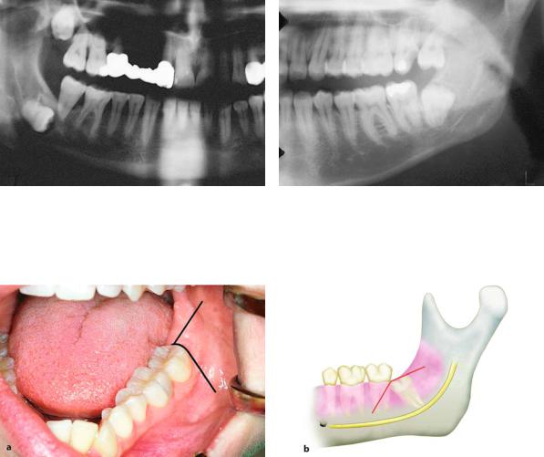
Fig. 7.16. Impacted right mandibular third molar, completely embedded at great depth in bone. Its extraction is considered difficult, because a large part of the bone must be removed and there is a risk of injury to the inferior alveolar nerve
Fig. 7.17. Impacted mandibular third molar, with the greatest part of the crown in the ramus of the mandible. Its extraction is considered difficult, because access through the anterior border of the ramus is difficult
Fig. 7.18 a, b. Incision for the creation of a triangular flap, which is indicated in certain cases of extraction of impacted mandibular third molars. a Clinical photograph. b Diagrammatic illustration
Class 3: There is no room between the second molar and the anterior border of the ramus, so that the entire impacted tooth or part of it is embedded in the ramus (Fig. 7.15 b, 3).
The above classification methods refer to all of the aforementioned positions of the impacted tooth. Furthermore, the number of roots of the impacted tooth and their relationship to the mandibular canal are taken into consideration. It is obvious that the cases belonging to Class 3 present more difficulty during the surgical procedure, because the extraction of the tooth requires removal of a relatively large amount of bone and there is a risk of fracturing the mandible and damaging the inferior alveolar nerve (Figs. 7.16, 7.17).
Types of Flaps. Two types of flaps may be used when surgically removing impacted mandibular third molars: the triangular and the envelope flap. The choice depends on the evaluation of the various data pertaining to the case (e.g., depth of impaction, position, etc.).
Triangular flap:
The incision for this type of flap begins at the anterior border of the ramus (external oblique ridge) with special care for the lingual nerve and extends as far as the distal aspect of the second molar, while the vertical releasing incision is made obliquely downwards and forward, ending in the vestibular fold (Fig. 7.18). In certain cases, e.g., when impaction is deep, to ensure a satisfactory surgical field or when the impacted tooth conceals the roots of the second molar, the incision may continue along the
128 F. D. Fragiskos
Fig. 7.19 a, b. Variation of incision shown in Fig. 7.18 (vertical releasing incision is distal to the first molar). The mesial extension of incision is necessary due to the position of the third molar compared to the second molar
Fig. 7.20 a,b. a Clinical photograph and b diagrammatic illustration showing incision for envelope flap
cervical line of the last tooth while the vertical incision begins at the distal aspect of the first molar
(Fig. 7.19).
Horizontal (envelope) flap:
The incision for the flap also begins at the anterior border of the ramus and extends as far as the distal aspect of the second molar, continuing along the cervical lines of the last two teeth, and ending at the mesial aspect of the first molar (Fig. 7.20). This type of flap is usually used in cases where impaction is relatively superficial.
Anesthesia. Anesthesia in cases of impacted mandibular third molars is achieved by: inferior alveolar nerve block, buccal nerve block, lingual nerve block, and local infiltration for hemostasis in the surgical field.
7.7.1.1 Removal of Bud
of Impacted Mandibular Third Molar
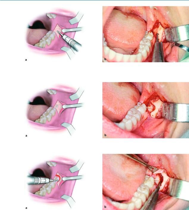
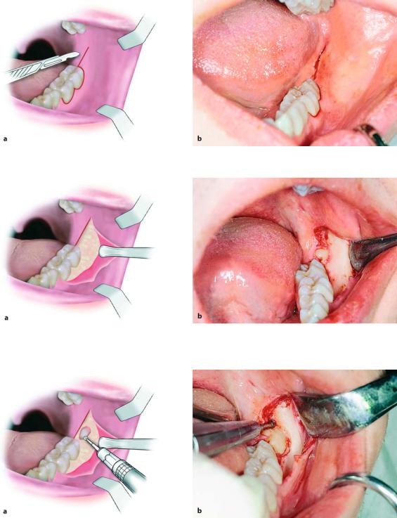
The following procedure is used to remove a bud of an impacted mandibular third molar (Fig. 7.21):
After a triangular incision is made using a scalpel with a no. 15 blade (Figs. 7.22, 7.23), the mucoperiosteal flap is reflected from the distal aspect of the second molar, continuing along the incision posteriorly as far as the anterior border of the ramus. The bone covering the tooth is removed using a round bur, until the entire crown is exposed (Figs. 7.24, 7.25). If the roots of the tooth have not yet developed, the tooth will roll around inside the alveolar crypt during the elevation attempt, so that the extraction is relatively difficult. That is why a pathway for removal must be ensured, by removing sufficient bone from the buccal

Chapter 7 Surgical Extraction of Impacted Teeth |
129 |
Fig. 7.21 a,b. Bud of mandibular third molar. a Radiograph and b clinical photograph of the relevant area
Fig. 7.22 a,b. Triangular incision using a scalpel with a no. 15 blade. a Diagrammatic illustration. b Clinical photograph
Fig. 7.23 a, b. Triangular incision completed. a Diagrammatic illustration. b Clinical photograph
and distal aspects of the crown of the tooth (guttering technique)1) (Fig. 7.26), so that its elevation from the socket is not hindered. After exposing the impacted tooth sufficiently, the straight elevator is placed in the mesial region and the tooth is elevated with a rotational movement distally (Figs. 7.27, 7.28).
1)The guttering technique involves the removal of bone by creating a groove on the buccal and distal aspects of the crown of the tooth, ensuring a pathway for removal that will facilitate its luxation. Extensive bone removal is thus avoided.
130 F. D. Fragiskos
Fig. 7.24 a,b. Reflection of the flap and use of a surgical handpiece to remove part of the bone over the crown of the impacted tooth. a Diagrammatic illustration. b Clinical photograph
Fig. 7.25 a,b. Exposure of the crown of an impacted tooth. a Diagrammatic illustration. b Clinical photograph
Fig. 7.26 a,b. Removal of bone from the buccal and distal aspects of the crown of an impacted tooth, to ensure a withdrawal pathway that will facilitate luxation (pathway of removal)
When the extraction of the impacted tooth is com- |
ined to ascertain if there are any sharp edges. If so, |
plete, the follicular sac, which is usually on the distal |
then a bone file or a special bur may be used to smooth |
aspect of the second molar, as well as bone fragments |
the bone (Fig. 7.29 b). After this procedure, the area is |
that may be present in the socket are removed |
irrigated with saline solution and the wound is su- |
(Figs. 7.29 a, 7.30). The bone margins are then exam- |
tured. The first suture is placed at the corner of the |

Chapter 7 Surgical Extraction of Impacted Teeth |
131 |
Fig. 7.27 a, b. Placement of the straight elevator between the mesial aspect of the impacted tooth and alveolar bone. a Diagrammatic illustration. b Clinical photograph
Fig. 7.28 a,b. Luxation of a tooth with rotational movement distally. Contact between the elevator and the distal surface of the second molar is avoided. a Diagrammatic illustration. b Clinical photograph
Fig. 7.29 a, b. a Removal of follicle using a hemostat and periapical curette. b Smoothing of bone edges of the wound using a bone file
flap to ensure correct repositioning of the flap, while the rest are placed along the posterior and vertical incisions (Fig. 7.31). After completing the surgical procedure, oral and written postoperative instructions are
given to the patient, and the sutures are removed 8 days later.
The procedure for care of the wound is the same as that for all cases of impacted teeth.
132 F. D. Fragiskos
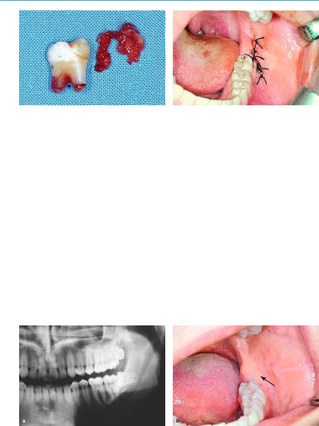
Fig. 7.30. Tooth and follicle after removal
7.7.1.2
Extraction of Impacted Third Molar in Horizontal Position
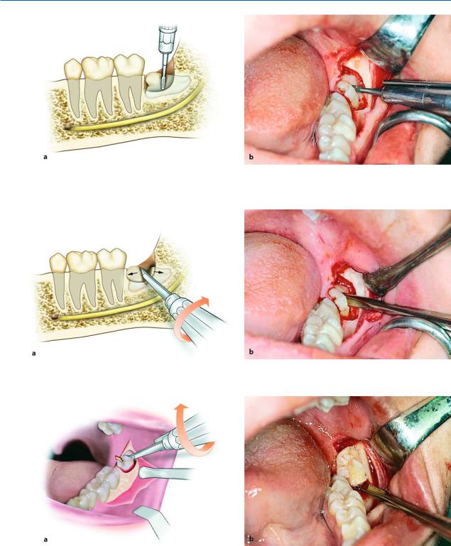
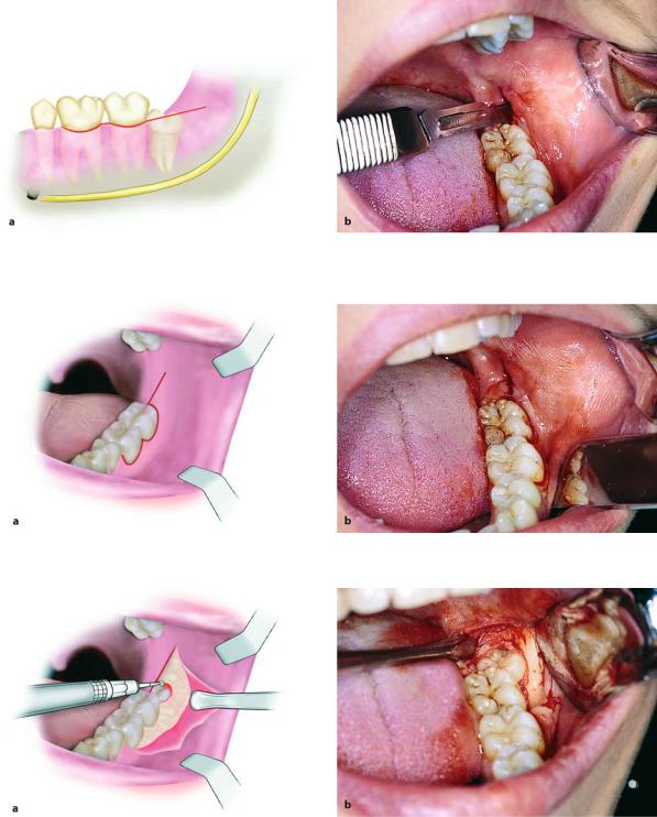
The extraction of an impacted third molar in a horizontal position is considered quite difficult and must be treated with particular care. This tooth may be superficial or deep in the bone and frequently its crown is close to the distal aspect of the second molar. The surgical procedure used to extract the impacted tooth, especially if the tooth is not deep in the bone (Fig. 7.32), is as follows. After making a horizontal incision, the mucoperiosteal flap is reflected (Figs. 7.33, 7.34). The bone covering the tooth is removed using a round bur, and the area is irrigated with a steady stream of saline solution, until the crown is entirely exposed (Fig. 7.35). A groove is then created vertically to the long axis of the tooth using a fissure bur, at the cervical line of the tooth, to separate the crown from the root (Fig. 7.36).
The groove created by the bur should not be deep, since the mandibular canal is often found in close proximity to the tooth and there is a risk of injuring or severing the inferior alveolar nerve. The straight ele-
Fig. 7.31. Operation site after suturing
vator is used, after being placed in the groove created earlier, to separate the crown from the root with a rotational movement (Fig. 7.37). The crown is removed separately, using the same elevator, with a rotational movement upwards, and the root is then easily removed, using a straight or angled elevator, whose blade end is placed in a purchase point created on the buccal aspect of the root (Figs. 7.38, 7.39). After smoothing the bone, the area is irrigated with saline solution and sutures are placed. The first suture is placed at the distal aspect of the second molar and the rest are placed at the interdental papillae and the posterior end of the incision (Figs. 7.40 a, b).
If the tooth has two roots, sectioning and removal of the crown are done as described above. Afterwards, if the roots of the impacted tooth have been separated during sectioning of the crown, they are easily removed one at a time, first the distal root and then the mesial root. If separation is not achieved at the beginning, then it must be carried out later. If not, during the attempt to extract both roots at the same time, there is a risk of fracturing the root tips, especially if they present curvature.
Fig. 7.32 a, b. a Radiograph showing impacted mandibular third molar in the horizontal position. b Clinical photograph of the area of the impacted tooth
Chapter 7 Surgical Extraction of Impacted Teeth |
133 |
Fig. 7.33 a, b. Horizontal incision using a scalpel with a no. 15 blade. a Diagrammatic illustration. b Clinical photograph
Fig. 7.34 a, b. Reflection of flap and retraction with the broad end of a periosteal elevator. a Diagrammatic illustration. b Clinical photograph
Fig. 7.35 a, b. Removal of bone using a round bur, to expose the crown of the impacted tooth
134 F. D. Fragiskos
Fig. 7.36 a, b. Sectioning tooth at the cervical line using a fissure bur. The diagrammatic illustration (a) shows the position beyond which the bur must not proceed, to avoid injury of the inferior alveolar nerve
Fig. 7.37 a, b. Separation of crown from the root, with rotation of the elevator in a groove created on the impacted tooth
Fig. 7.38 a, b. Diagrammatic illustration (a) and clinical photograph (b) showing removal of the crown of the tooth using a straight elevator
Chapter 7 Surgical Extraction of Impacted Teeth |
135 |
Fig. 7.39 a, b. Luxation of the root of an impacted tooth using an angled Seldin elevator
Fig. 7.40 a, b. a Operation site after removal of tooth. b Surgical field after suturing
7.7.1.3
Extraction of Third Molar with Mesioangular Impaction
This tooth presents inclination of the crown mesially, to a greater or lesser degree, so that the mesial cusps are in contact with the distal aspect of the second molar. Often, for the extraction of such an impacted tooth, sectioning is considered necessary in addition to bone removal. The most common case requiring sectioning of the tooth is when it has mesioangular impaction and the crown is just below or below the cervical line of the second molar (Fig. 7.41). In this case, the technique used for its removal is as follows:
After creating a horizontal incision (Figs. 7.42, 7.43), the mucoperiosteal flap is reflected. Reflection begins at the interdental papilla at the mesial aspect of the first molar and continues posteriorly, along the incision as far as the anterior border of the ramus (Fig. 7.44).
The bone covering the tooth is removed using a round bur, until the entire crown is exposed (Fig. 7.45). Afterwards, using a fissure bur, sufficient bone is removed using the guttering technique, on the buccal and mainly the distal aspect of the tooth (Fig. 7.46). If the tooth is single-rooted, to facilitate its removal, the mesial portion of the tooth is removed first, while the remaining portion is then luxated. If the tooth has two roots, the roots may be separated and each root may be extracted in the easiest direction, depending on its curvature. More specifically, a deep vertical groove is made on the crown of the tooth using a fissure bur, approximately as far as the intraradicular bone (Fig. 7.47). Sectioning is achieved using a straight elevator, which, after being placed in the groove already created, is rotated and separates the roots (Figs. 7.48, 7.49). This separation of the tooth allows for limited bone removal, thus causing less trauma and faster completion of the surgical procedure.
136 F. D. Fragiskos
Fig. 7.41 a, b. a Radiograph showing impacted mandibular third molar (partial bone impaction) with mesioangular position. b Clinical photograph of area of impaction
Fig. 7.42 a, b. Horizontal incision (for envelope flap) using a scalpel with a no. 15 blade. a Diagrammatic illustration. b Clinical photograph
Fig. 7.43 a, b. Diagrammatic illustration (a) and clinical photograph (b) after completion of incision

Chapter 7 Surgical Extraction of Impacted Teeth |
137 |
Fig. 7.44 a, b. Reflection of flap and retraction using the broad end of the periosteal elevator
Fig. 7.45 a, b. Exposure of the crown of the tooth using a round bur. a Diagrammatic illustration. b Clinical photograph
Fig. 7.46 a, b. Removal of bone using the guttering technique. A groove is created buccally, which extends distally to the crown of the tooth, creating room that will facilitate its luxation
138 F. D. Fragiskos
Fig. 7.47 a, b. Sectioning of the crown of an impacted tooth, in the buccolingual direction, which extends as far as the intraradicular bone. a Diagrammatic illustration. b Clinical photograph
Fig. 7.48 a, b. Separation of tooth with positioning and rotation of straight elevator in created groove
Fig. 7.49 a, b. Diagrammatic illustration (a) and clinical photograph (b) of the impacted tooth after separation
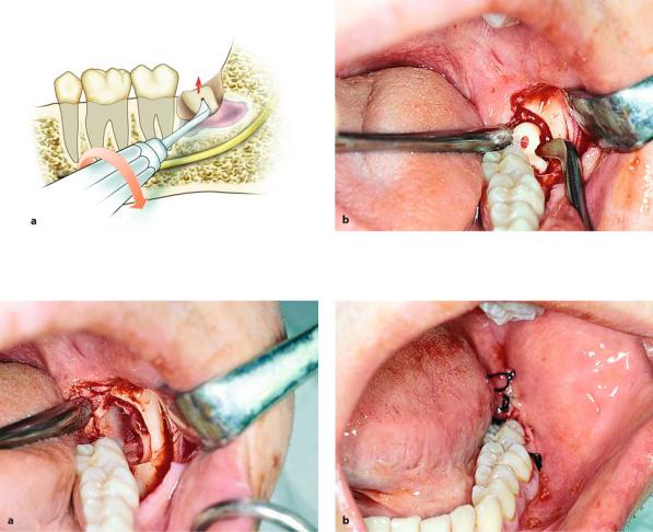
The tooth is removed in two steps. First the distal root is elevated together with part of the crown (Fig. 7.50), and then, after placing the blade of the
elevator on the mesial aspect of the tooth, the other root is removed with rotational movement distally (Figs. 7.51, 7.52). Care of the socket follows, as does

Chapter 7 Surgical Extraction of Impacted Teeth |
139 |
Fig. 7.50 a, b. Luxation of the distal segment of the tooth with rotation of the elevator distally. a Diagrammatic illustration. b Clinical photograph
Fig. 7.51 a, b. Luxation of the mesial segment of an impacted tooth using a straight elevator. a Diagrammatic illustration. b Clinical photograph
Fig. 7.52. Segments of tooth after removal |
Fig. 7.53. Empty socket after extraction of tooth |
suturing of the wound, which is performed in exactly the same way as in other cases of impacted teeth (Figs. 7.53, 7.54 a, b).
140 F. D. Fragiskos
Fig. 7.54 a, b. a Removal of follicle using a hemostat and periapical curette. b Surgical field after placement of sutures
7.7.1.4
Extraction of Third Molar with Distoangular Impaction
Removal of this tooth is considered quite difficult, since it is located beneath the anterior border of the ramus with a fair amount of bone above its crown, while its roots are inclined somewhat near the distal root of the second molar (Fig. 7.55). Therefore, it is impossible to remove the tooth in one piece, unless a large amount of bone is removed.
The technique for creating the flap and removing bone is similar to that mentioned for the tooth with mesioangular impaction (Figs. 7.56–7.59). The only difference is the separation of the tooth, which is performed so that its removal can be achieved with minimal bone removal. More specifically, the distal portion of the crown is sectioned using a fissure bur, and removed, while the remaining segment of the tooth is then luxated, after placing the elevator at the mesial aspect of the tooth (Figs. 7.60–7.63). Care of the socket and suturing of the flap are carried out exactly as in other cases of impacted teeth (Fig. 7.64).
Fig. 7.55 a,b. a Radiograph showing impacted mandibular third molar (partial bone impaction) with a distoangular position. b Clinical photograph of the area of impaction
Chapter 7 Surgical Extraction of Impacted Teeth |
141 |
Fig. 7.56 a, b. The horizontal incision extends as far as the mesial aspect of the first molar. a Diagrammatic illustration. b Clinical photograph
Fig. 7.57 a,b. Diagrammatic illustration (a) and clinical photograph (b) showing the horizontal incision upon completion
Fig. 7.58 a, b. Reflection of the mucoperiosteal flap, and partial exposure of the crown of the impacted tooth. a Diagrammatic illustration. b Clinical photograph

142 F. D. Fragiskos
Fig. 7.59 a, b. Removal of bone on the buccal and distal aspects of the crown of the tooth. The groove is created to facilitate luxation. a Diagrammatic illustration. b Clinical photograph
Fig. 7.60 a, b. Sectioning of the distal portion of the crown of the impacted tooth using a fissure bur. a Diagrammatic illustration. b Clinical photograph
Fig. 7.61 a, b. Removal of the distal part of the crown using a straight elevator. a Diagrammatic illustration. b Clinical photograph
Chapter 7 Surgical Extraction of Impacted Teeth |
143 |
Fig. 7.62 a, b. Luxation of the impacted tooth in the distal direction, after creating a pathway for removal. a Diagrammatic illustration. b Clinical photograph
Fig. 7.63. Tooth after removal
7.7.1.5
Extraction of Impacted Third Molar in Edentulous Patient
One of the major problems faced in surgery of impacted mandibular third molars in dentulous patients is the second molar, which often hinders manipulations during the operation. Therefore, the surgical extraction of the third molar in edentulous patients is much
Fig. 7.64. Surgical field after suturing
easier and faster compared to dentulous patients, if the surgeon adheres to the rules regarding the surgical technique. The techniques for creation of the flap and removal of bone are the same as those used for other cases of impacted teeth. The second molar is often missing; therefore, tooth sectioning is not necessary because it may easily be extracted using either the elevator or tooth forceps, after the bone surrounding the tooth has been removed (Figs. 7.65–7.71).
144 F. D. Fragiskos
Fig. 7.65. Radiograph showing impacted right mandibular |
Fig. 7.66. Incision created for the removal of an impacted |
third molar in an edentulous area |
tooth |
Fig. 7.67. Creation of flap and removal of bone from the buccal and distal aspects of the crown of the tooth
Fig. 7.68. Positioning of elevator with T-shaped handles for luxation of the impacted tooth
Fig. 7.69. Removal of tooth with rotation of elevator up- Fig. 7.70. Surgical field after removal of tooth wards
Chapter 7 Surgical Extraction of Impacted Teeth |
145 |
Fig. 7.71 a, b. a Tooth after removal from socket. b Surgical field after placement of sutures
7.7.2
Impacted Premolar
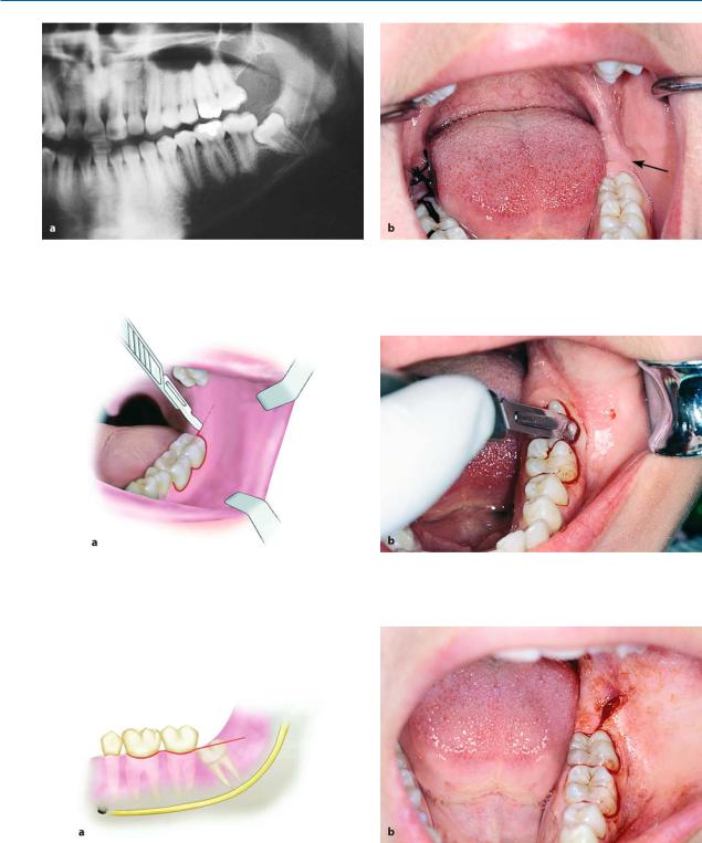
Impacted mandibular premolars may be localized lingually or buccally, in a vertical position, and with their crowns often wedged underneath adjacent teeth.
When localization is buccal (Fig. 7.72), a trapezoidal flap is created very carefully, making the vertical incisions some way from the mental foramen, to avoid injuring the mental neurovascular bundle.
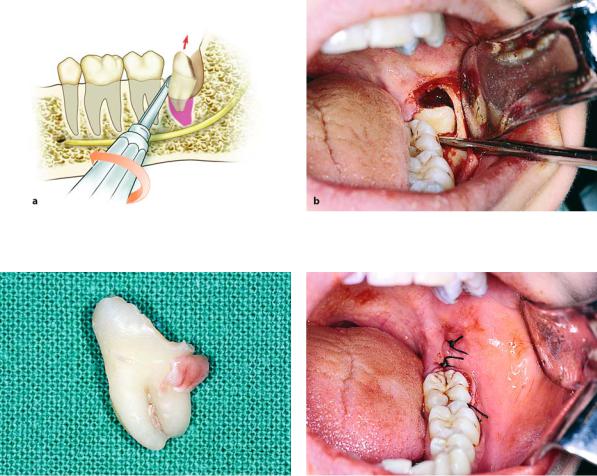
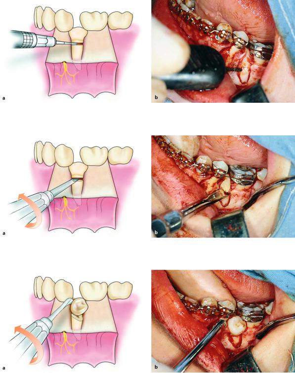
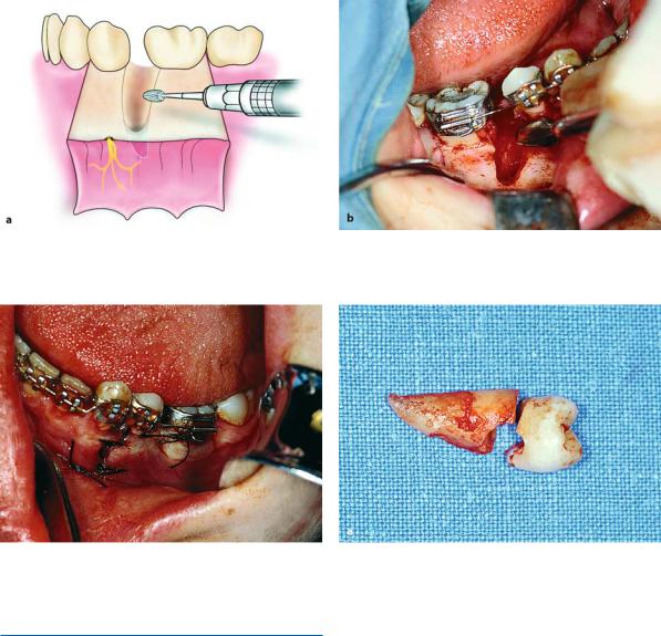
After creating the flap (Fig. 7.73), bone is removed along the impacted tooth taking care not to injure the adjacent teeth (Figs. 7.74, 7.75). A fissure bur is used to section the tooth at approximately the cervical line and the crown is separated from the root using the straight elevator (Figs. 7.76, 7.77). Afterwards, the crown is removed from between the teeth (Figs. 7.78, 7.79). Extraction of the root is achieved using an angled elevator, whose blade tip is placed in the purchase point created on the buccal aspect of the root. The root is thus easily luxated upwards and removed from the socket (Figs. 7.80–7.84).
Fig. 7.72 a, b. a Radiograph showing impacted mandibular second premolar. b Clinical photograph of area of impaction
146 F. D. Fragiskos
Fig. 7.73 a, b. Creation of trapezoidal flap for removal of an impacted tooth. The course of the mental nerve after emerging from the mental foramen is shown in yellow. a Diagrammatic illustration. b Clinical photograph
Fig. 7.74 a, b. Removal of buccal bone to expose tooth. a Diagrammatic illustration. b Clinical photograph
Fig. 7.75 a, b. Exposure of part of the buccal aspect of the root, after removal of a large amount of buccal bone. a Diagrammatic illustration. b Clinical photograph
Chapter 7 Surgical Extraction of Impacted Teeth |
147 |
Fig. 7.76 a, b. Partial sectioning of the crown from the root of the tooth using a bur, in the buccolingual direction. a Diagrammatic illustration. b Clinical photograph
Fig. 7.77 a, b. Separation of the impacted tooth into two segments using the straight elevator. a Diagrammatic illustration. b Clinical photograph
Fig. 7.78 a, b. Removal of the crown using Seldin elevator or elevator with T-shaped handles. a Diagrammatic illustration. b Clinical photograph
148 F. D. Fragiskos
Fig. 7.79 a,b. Portion of remaining root after removal of the crown. a Diagrammatic illustration. b Clinical photograph
Fig. 7.80 a,b. Positioning of angled elevator in the purchase point of the root, for luxation
Fig. 7.81 a, b. Final step in removal of the root from the socket using the angled Seldin elevator. a Diagrammatic illustration. b Clinical photograph
Chapter 7 Surgical Extraction of Impacted Teeth |
149 |
Fig. 7.82 a, b. Smoothing of bone edges of the wound using a surgical bur. a Diagrammatic illustration. b Clinical photograph
Fig. 7.83. Surgical field after placement of sutures
7.7.3
Impacted Canine
Impacted mandibular canines are usually localized buccally and generally next to or underneath the roots of the incisors, in a vertical, horizontal, or oblique position.
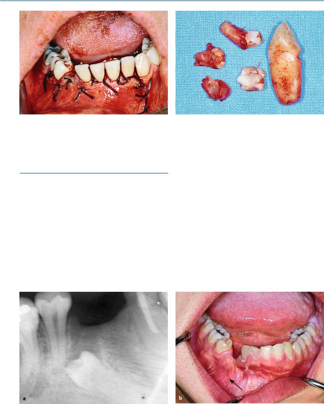
The case presented involves an impacted canine in a vertical position, and the surgical procedure was performed with concurrent removal of odontomas found nearby (Fig. 7.85). First a trapezoidal flap is cre-
Fig. 7.84. Impacted premolar with groove on the surface of the root
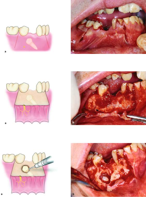
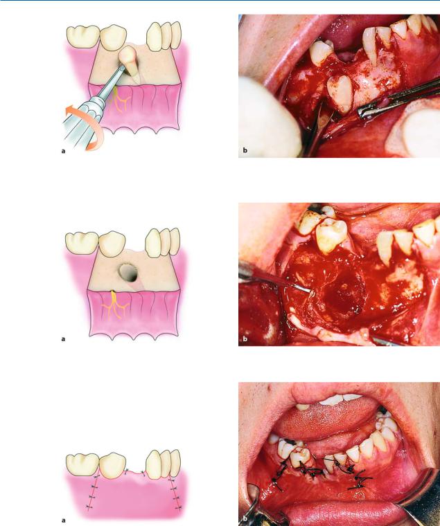
ated that ensures a satisfactory surgical field and access, which is also necessary because of the presence of the odontomas (Figs. 7.86, 7.87). The crown of the impacted tooth is exposed using a round bur, while a fissure bur is used to remove bone around the crown to permit positioning of the elevator (Fig. 7.88). After this procedure, the tooth is luxated mesially and distally and the odontomas are then removed using a narrow angled elevator, after being exposed using a narrow round bur (Figs. 7.89, 7.90). After care of the wound, the flap is repositioned and interrupted sutures are placed (Figs. 7.91, 7.92).
150 F. D. Fragiskos
Fig. 7.85 a, b. a Panoramic radiograph showing an impacted mandibular canine and odontomas in the anterior area of the mandible. b Clinical photograph of the radiograph
shown in a, showing the deciduous canine, which remained in the dental arch due to impaction of the permanent canine and the presence of odontomas
Fig. 7.86 a,b. Trapezoidal incision extending from the left lateral incisor as far as the first premolar of the opposite side of the mandible. a Diagrammatic illustration. b Clinical photograph
Fig. 7.87 a, b. Reflection of the flap, which ensures satisfactory access to the surgical field, necessary due to the presence of odontomas, other than the impacted tooth. a Diagrammatic illustration. b Clinical photograph

Chapter 7 Surgical Extraction of Impacted Teeth |
151 |
Fig. 7.88 a,b. Exposure of the crown of the impacted tooth using a surgical bur. a Diagrammatic illustration. b Clinical photograph
Fig. 7.89 a, b. Luxation using the blade of the elevator alternately on the mesial and distal aspects of crown of tooth. a Diagrammatic illustration. b Clinical photograph
Fig. 7.90 a, b. Surgical field after removal of the impacted tooth and odontomas. a Diagrammatic illustration. b Clinical photograph
152 F. D. Fragiskos
Fig. 7.91. Surgical field after suturing
7.7.4
Premolar with Deep Impaction
When the impacted premolar is deep in the bone (Fig. 7.93), the procedure for its removal is generally as follows. First a trapezoidal incision is made (Fig. 7.94), and the mucoperiosteal flap is reflected, which, due to
Fig. 7.92. Canine and odontomas after removal
the position of the impacted tooth, must be done very carefully, until the mental foramen and the emerging neurovascular bundle are visible (Fig. 7.95).
When this procedure is complete, the bone covering the crown and part of the root is removed (Fig. 7.96).
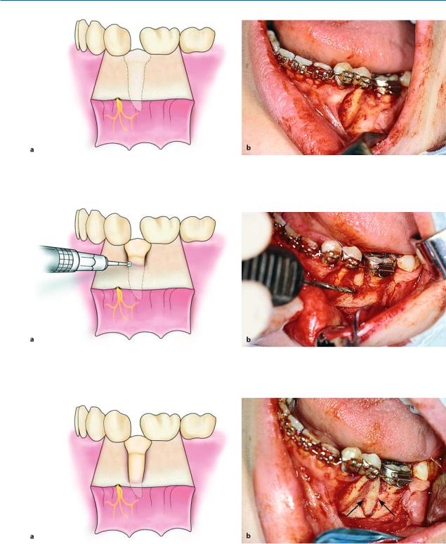
The straight elevator is then placed on the mesial or distal aspect, and using alternate movements, the tooth is luxated buccally (Figs. 7.97–7.99).
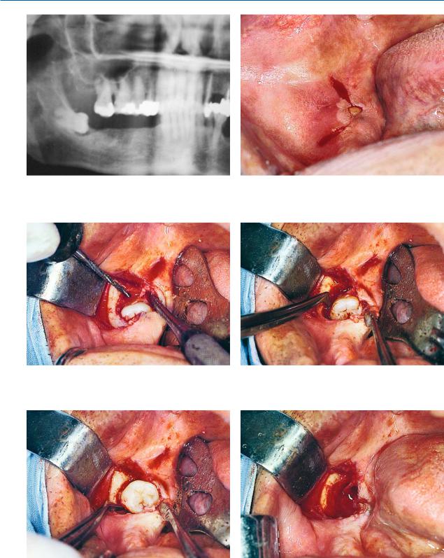
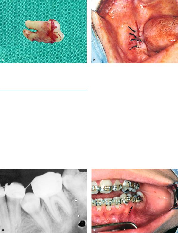
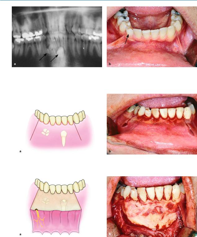
Fig. 7.93 a, b. a Radiograph showing the mandibular second premolar with complete bone impaction. b Clinical photograph of the area of impaction
Chapter 7 Surgical Extraction of Impacted Teeth |
153 |
Fig. 7.94 a, b. Completed trapezoidal incision. a Diagrammatic illustration. b Clinical photograph. The area of the mental foramen (yellow circle in a) is avoided at vertical releasing incision
Fig. 7.95 a, b. Flap reflection. Arrow points to the mental nerve, which was prepared to avoid injury. a Diagrammatic illustration. b Clinical photograph
Fig. 7.96 a, b. Removal of buccal bone to expose the crown of the impacted tooth. a Diagrammatic illustration. b Clinical photograph
154 F. D. Fragiskos
Fig. 7.97 a, b. Luxation of the tooth using rotational movements in the mesial direction. a Diagrammatic illustration. b Clinical photograph
Fig. 7.98 a, b. Surgical field after removal of the impacted tooth. a Diagrammatic illustration. b Clinical photograph
Fig. 7.99 a, b. Surgical field after suturing. a Diagrammatic illustration. b Clinical photograph