


vk.com/club152685050Fluid Flow in an Exhaust|Manifoldvk.com/id446425943
Figure 1.2: Mass Flow Rate History
c.Similarly, the residuals history will be plotted in the Scaled Residuals tab in the graphics window (Figure 1.3: Residuals (p. 26)).
Figure 1.3: Residuals
9. Save the case and data files (manifold_solution.cas and manifold_solution.dat).

 File → Write → Case & Data...
1.4.10. Postprocessing
1.Display path lines highlighting the flow field (Figure 1.4: Pathlines Through the Manifold (p. 28)).
 Results → Graphics → Pathlines → New...
|
Release 2019 R1 - © ANSYS,Inc.All rights reserved.- Contains proprietary and confidential information |
26 |
of ANSYS, Inc. and its subsidiaries and affiliates. |
vk.com/club152685050 | vk.com/id446425943 |
Setup and Solution |
a.Keep the default of pathlines-1 for the Name.
b.Select Particle Variables... and Time from the Color by drop-down lists.
c.Enable Accuracy Control under Options.
d.Set the Path Skip value to 5.
e.Select Accuracy Control from the Options list.
f.Select inlet, inlet1, and inlet2 from the Release from Surfaces list.
g.Click Save/Display and close the Pathlines dialog box.
The new pathlines-1 definition appears under the Results/Graphics/Pathlines tree branch. To edit your surface definition, right-click it and select Edit... from the menu that opens.
Release 2019 R1 - © ANSYS,Inc.All rights reserved.- Contains proprietary and confidential information |
|
of ANSYS, Inc. and its subsidiaries and affiliates. |
27 |
vk.com/club152685050Fluid Flow in an Exhaust|Manifoldvk.com/id446425943
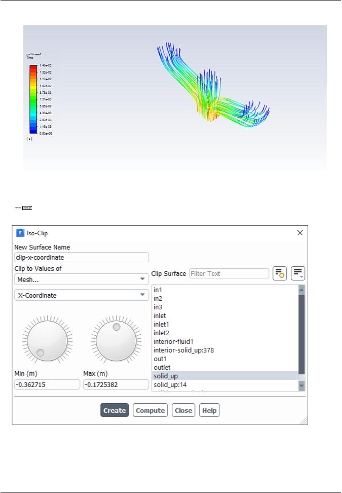
Figure 1.4: Pathlines Through the Manifold
2.Create a clipped surface through the manifold geometry.

 Results → Surface → Create → Iso-Clip...
a.Enter clip-x-coordinate for Name.
b.Select Mesh... and X-Coordinate from the Clip to Values of drop-down lists.
c.Keep the Min value at its minimum setting, and adjust the Max value to be at its halfway point.
|
Release 2019 R1 - © ANSYS,Inc.All rights reserved.- Contains proprietary and confidential information |
28 |
of ANSYS, Inc. and its subsidiaries and affiliates. |

vk.com/club152685050 | vk.com/id446425943 |
Setup and Solution |
d.Select solid_up from the Clip Surface list.
e.Click Create and close the Iso-Clip dialog box.
The new clip-x-coordinate definition appears under the Results/Surfaces tree branch. To edit your surface definition, right-click it and select Edit... from the menu that opens.
3.Create a scene containing the mesh and the path lines.


 Results → Scene
  New...
a.Keep the default scene-1 for the Name.
b.Create a new mesh object to add to the scene.
i. Click New Object and select Mesh to open the Mesh Display dialog box.
Release 2019 R1 - © ANSYS,Inc.All rights reserved.- Contains proprietary and confidential information |
|
of ANSYS, Inc. and its subsidiaries and affiliates. |
29 |

vk.com/club152685050Fluid Flow in an Exhaust|Manifoldvk.com/id446425943
ii.Select clip-x-coordinate under the Surfaces list.
iii.Click Save/Display and close the Mesh Display dialog box.
The new mesh-1 definition appears under the Results/Graphics/Mesh tree branch. The new object also appears in the Scene dialog box.
c.In the Scene dialog box, set the Transparency to 50.
d.Click Save & Display and close the Scene dialog box.
|
Release 2019 R1 - © ANSYS,Inc.All rights reserved.- Contains proprietary and confidential information |
30 |
of ANSYS, Inc. and its subsidiaries and affiliates. |

vk.com/club152685050 | vk.com/id446425943 |
Setup and Solution |
Figure 1.5: Scene Containing the Mesh and Pathlines Throughout the Manifold
4.Create and define contours of velocity magnitude at the outlet along with the mesh.
 Results → Graphics → Contours → New...
Release 2019 R1 - © ANSYS,Inc.All rights reserved.- Contains proprietary and confidential information |
|
of ANSYS, Inc. and its subsidiaries and affiliates. |
31 |

vk.com/club152685050Fluid Flow in an Exhaust|Manifoldvk.com/id446425943
a.Enter contour-velocity for the Name.
b.Select Velocity... and Velocity Magnitude from the Contours of drop-down lists.
c.Select outlet from the Surfaces list.
d.Disable Node Values under Options.
e.Enable Draw Mesh under Options.
This displays the Mesh Display dialog box.
In the Mesh Display dialog box, deselect all surfaces, select the out surface, click Display and close the dialog.
f.Click Create and close the Contours dialog box.
|
Release 2019 R1 - © ANSYS,Inc.All rights reserved.- Contains proprietary and confidential information |
32 |
of ANSYS, Inc. and its subsidiaries and affiliates. |