

UG-VIPSUITE |
Avalon-MM Slave Interfaces |
2-25 |
|
2015.01.23 |
|||
|
|
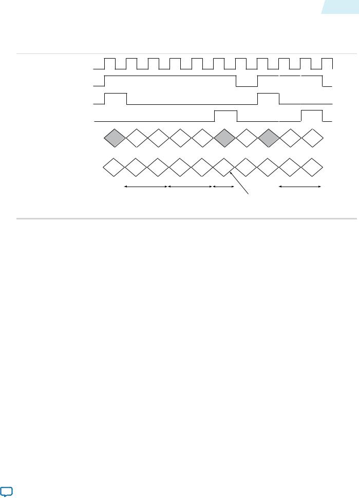
Example 3 (Control Data Transfer)
Figure 2-18: Timing Diagram Showing Control Packet Transfer
This figure shows the transfer of a control packet for a field of 720×480 video (with field height 240).
clock |
|
|
|
|
|
|
|
|
din_valid |
|
|
|
|
|
|
|
|
din_startofpacket |
|
|
|
|
|
|
|
|
din_endofpacket |
|
|
|
|
|
|
|
|
CbCr din_data(13:10) |
|
0x2 |
0x0 |
0x0 |
0x0 |
|
|
|
Y din_data(3:0) |
0xF |
0x0 |
0xD |
0x0 |
0xF |
10xx |
0x0 |
|
|
|
|||||||
|
|
720(0x02D0) |
240(0x00F0) |
if0 |
binary |
image data |
||
|
|
f0 - 10xx |
||||||
|
|
|
|
|
|
|
f1 - 11xx |
|
|
|
|
|
|
|
|
p - 00xx |
|
The packet is transferred over an interface configured for 10-bit data with two color planes in parallel. Each word of the control packet is transferred in the lowest four bits of a color plane, starting with bits 3:0, then 13:10.
Avalon-MM Slave Interfaces
The Video and Image Processing Suite IP cores that permit run-time control of some aspects of their behavior, use a common type of Avalon-MM slave interface for this purpose.
Each slave interface provides access to a set of control registers which must be set by external hardware. You must assume that these registers power up in an undefined state. The set of available control registers and the width in binary bits of each register varies with each control interface.
Interfaces |
Altera Corporation |
|
|
Send Feedback

2-26 |
Avalon-MM Slave Interfaces |
UG-VIPSUITE |
|
2015.01.23 |
|||
|
|
The first two registers of every control interface perform the following two functions (the others vary with each control interface):
•Register 0 is the Go register. Bit zero of this register is the Go bit. A few cycles after the function comes out of reset, it writes a zero in the Go bit (remember that all registers in Avalon-MM control slaves power up in an undefined state).
•Although there are a few exceptions, most Video and Image Processing Suite IP cores stop at the beginning of an image data packet if the Go bit is set to 0. This allows you to stop the IP core and to program run-time control data before the processing of the image data begins. A few cycles after the Go bit is set by external logic connected to the control port, the IP core begins processing image data. If the Go bit is unset while data is being processed, then the IP core stops processing data again at the beginning of the next image data packet and waits until the Go bit is set by external logic.
•Register 1 is the Status register. Bit zero of this register is the Status bit, the function does not use all other bits. The function sets the Status bit to 1 when it is running, and zero otherwise. External logic attached to the control port must not attempt to write to the Status register.
The following pseudo-code illustrates the design of functions that double-buffer their control (that is, all IP cores except the Gamma Corrector and some Scaler II parameterizations):
go = 0; while (true)
{
read_non_image_data_packets(); status = 0;
while (go != 1) wait;
read_control(); // Copies control to internal registers status = 1;
send_image_data_header(); process_frame();
}
For IP cores that do not double buffer their control data, the algorithm described in the previous paragraph is still largely applicable but the changes to the control register will affect the current frame.
Most Video and Image Processing Suite IP cores with a slave interface read and propagate non-image data packets from the input stream until the image data header (0) of an image data packet has been received. The status bit is then set to 0 and the IP core waits until the Go bit is set to 1 if it is not already. Once the Go bit is set to 1, the IP core buffers control data, sets its status bit back to 1 and starts processing image data.
Note: There is a small amount of buffering at the input of each Video and Image Processing Suite IP core and you must expect that a few samples are read and stored past the image data header even if the function is stalled.
You can use the Go and Status registers in combination to synchronize changes in control data to the start and end of frames. For example, suppose you want to build a system with a Gamma Corrector IP core where the gamma look-up table is updated between each video frame.
Altera Corporation |
Interfaces |
|
|
Send Feedback

UG-VIPSUITE |
Specification of the Type of Avalon-MM Slave Interfaces |
2-27 |
|
2015.01.23 |
|||
|
|
You can build logic (or program a Nios II processor) to control the gamma corrector as follows:
1.Set the Go bit to zero. This causes the IP core to stop processing at the end of the current frame.
2.Poll the Status bit until the IP core sets it to zero. This occurs at the end of the current frame, after the IP core has stopped processing data.
3.Update the gamma look-up table.
4.Set the Go bit to one. This causes the IP core to start processing the next frame.
5.Poll the Status bit until the IP core sets it to one. This occurs when the IP core has started processing the next frame (and therefore setting the Go bit to zero causes it to stop processing at the end of the next frame).
6.Repeat steps 1 to 5 until all frames are processed.
This procedure ensures that the update is performed exactly once per frame and that the IP core is not processing data while the update is performed.
When using IP cores which double-buffer control data, such as the Alpha Blending Mixer, a more simple process may be sufficient:
1.Set the Go bit to zero. This causes the IP core to stop if it gets to the end of a frame while the update is in progress.
2.Update the control data.
3.Set the Go bit to one.
The next time a new frame is started after the Go bit is set to one, the new control data is loaded into the IP core.
The reading on non-video packets is performed by handling any packet until one arrives with type 0. This means that when the Go bit is checked, the non-video type has been taken out of the stream but the video is retained.
Specification of the Type of Avalon-MM Slave Interfaces
The Avalon-MM slave interfaces only use certain signals for Video and Image Processing Suite IP cores.
Table 2-12: Avalon-MM Slave Interface Signal Types
The table below lists the signals that the Avalon-MM slave interfaces use in the Video and Image Processing Suite. The unused signals are not listed.
Note: The slave interfaces of the Video and Image Processing IP cores may use either chipselect or read.
Signal |
|
Width |
|
Direction |
|
|
|
|
|
|
|
chipselect |
|
1 |
|
Input |
|
|
|
|
|
|
|
read |
|
1 |
|
Input |
|
|
|
|
|
|
|
address |
|
Variable |
|
Input |
|
|
|
|
|
|
|
readdata |
|
Variable |
|
Output |
|
|
|
|
|
|
|
write |
|
1 |
|
Input |
|
|
|
|
|
|
|
writedata(5) |
|
Variable |
|
Input |
|
|
|
|
|
|
|
(5) For slave interfaces that do not have a predefined number of wait cycles to service a read or a write request.
Interfaces |
Altera Corporation |
|
|
Send Feedback