


Control Synchronizer IP Core 11
2015.01.23
UG-VIPSUITE |
Subscribe |
Send Feedback |
The Control Synchronizer IP core synchronizes the configuration change of IP cores with an event in a video stream. For example, the IP core can synchronize the changing of a position of a video layer with the changing of the size of the layer.
The Control Synchronizer IP core has the following ports:
•Avalon Video Streaming Input and Output port—passes through Avalon-ST Video data, and monitors the data for trigger events.
•Avalon Master port—writes data to the Avalon Slave control ports of other IP cores when the Control Synchronizer IP core detects a trigger event.
•Avalon Slave port—sets the data to be written and the addresses that the data must be written to when the IP core detects a trigger event.
•Avalon Slave Control port—disables or enables the trigger condition. You can configure the IP core before compilation to disable this port after every trigger event; disabling this port is useful if you want the IP core to trigger only on a single event.
The following events trigger the Control Synchronizer IP core:
•the start of a video data packet.
•a change in the width or height field of a control data packet that describes the next video data packet.
When the Control Synchronizer IP core detects a trigger event, the following sequence of events take place:
1.The IP core immediately stalls the Avalon-ST video data flowing through the IP core.
2.The stall freezes the state of other IP cores on the same video processing data path that do not have buffering in between.
3.The IP core then writes the data stored in its Avalon Slave register map to the addresses that are also specified in the register map.
4.After writing is complete, the IP core resumes the Avalon-ST video data flowing through it. This ensures that any cores after the Control Synchronizer IP core have their control data updated before the start of the video data packet to which the control data applies.
5.When all the writes from a Control Synchronizer IP core trigger are complete, an interrupt is triggered or is initiated, which is the “completion of writes” interrupt.
© 2015 Altera Corporation. All rights reserved. ALTERA, ARRIA, CYCLONE, ENPIRION, MAX, MEGACORE, NIOS, QUARTUS and STRATIX words and logos are trademarks of Altera Corporation and registered in the U.S. Patent and Trademark Office and in other countries. All other words and logos identified as trademarks or service marks are the property of their respective holders as described at www.altera.com/common/legal.html. Altera warrants performance of its semiconductor products to current specifications in accordance with Altera's standard warranty, but reserves the right to make changes to any products and services at any time without notice. Altera assumes no responsibility or liability arising out of the application or use of any information, product, or service described herein except as expressly agreed to in writing by Altera. Altera customers are advised to obtain the latest version of device specifications before relying on any published information and before placing orders for products or services.
ISO 9001:2008 Registered
www.altera.com
101 Innovation Drive, San Jose, CA 95134
11-2 |
Using the Control Synchronizer IP Core |
UG-VIPSUITE |
|
2015.01.23 |
|||
|
|
Using the Control Synchronizer IP Core
The example illustrates how the Control Synchronizer IP Core is set to trigger on the changing of the width field of control data packets.
In the following example, the Control Synchronizer IP Core is placed in a system containing the following IP cores:
•Test Pattern Generator
•Frame Buffer
•Scaler II
The Control Synchronizer IP core must synchronize a change of the width of the generated video packets with a change to the Scaler output size in the following conditions:
•The Scaler maintains a scaling ratio of 1:1 (no scaling)
•The Frame Buffer is configured to drop and repeat making it impossible to calculate packets streamed into the frame buffer are streamed out to the Scaler.
•The Scaler cannot be configured in advance of a certain video data packet.
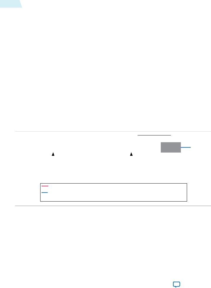
The Control Synchronizer IP Core solves the problem through the following sequence of events: 1. Sets up the change of video width.
Figure 11-1: Change of Video Width
|
|
|
|
|
|
|
|
|
Avalon MM |
|
|
|||
|
|
|
|
|
|
|
|
|
|
|||||
|
|
|
|
|
|
|
|
|
|
Master |
|
|
|
|
|
Test Pattern |
|
|
Frame |
|
|
|
Control |
|
|||||
Avalon |
Generator |
|
|
Buffer |
|
|
|
Synchronizer |
MM |
|||||
MM |
|
|
|
|
|
|
|
|
|
Avalon |
||||
|
|
|
|
|
|
|
|
|||||||
|
|
|
|
|
|
Nios II CPU |
|
|
|
|
|
|
|
|
|
|
|
CPU Writes to |
|
|
CPU Writes to Control |
||||||||
|
|
|
|
|
|
|
||||||||
|
|
|
Test Pattern |
|
|
|
Synchronizer, Configures it to |
|||||||
|
|
|
Generator, |
|
Change Scaler Output Size to 320 Width |
|||||||||
|
changing frame width to 320 |
|
|
When a Change in Width is Detected |
||||||||||
 Avalon MM
Scaler
Red Line Indicates Control Data Packet and Video Data Packet Pair Number 4 (Width 640)
Blue Line Indicates Control Data Packet and Video Data Packet Pair Number 0 (Width 640)
Control Data packet and Video Data Packet Pair Numbers 1, 2 and 3 are Stored in the Frame Buffer
2.The Test Pattern Generator changes the size of its Video Data Packet and Control Data Packet pairs to 320 width. It is not known when this change will propagate through the Frame Buffer to the Scaler.
Altera Corporation |
Control Synchronizer IP Core |
|
|
Send Feedback

UG-VIPSUITE |
|
|
Using the Control Synchronizer IP Core |
11-3 |
||||||||||||
2015.01.23 |
|
|
|
|
|
|
|
|||||||||
|
|
|
|
|
|
|
|
|
|
|
|
|
|
|
||
|
Figure 11-2: Changing Video Width |
|
|
|
|
|
|
|
|
|
|
|||||
|
|
|
|
|
|
|
|
|
|
|
|
|
|
|||
|
|
|
|
|
|
|
|
Avalon MM |
|
|
|
Avalon MM |
|
|||
|
|
|
|
|
|
|
|
|
|
|
|
|||||
|
|
|
|
|
|
|
|
|
Master |
|
|
|
|
|||
|
|
Test Pattern |
|
|
Frame |
|
Control |
|
Scaler |
|
|
|||||
|
Avalon |
Generator |
|
|
Buffer |
|
Synchronizer |
MM |
|
|
||||||
|
|
|
|
|
|
|
|
|||||||||
|
MM |
|
|
|
|
|
|
|
Avalon |
|
|
|
|
|||
|
|
|
|
|
|
|
|
|
|
|||||||
|
|
|
|
|
|
|
Nios II CPU |
|
|
|
|
|
|
|
|
|
|
|
|
|
|
|
|
|
|
|
|
|
|
|
|
|
|
|
|
|
|
|
|
|
|
|
|
|
|
|
|
|
|
|
Red Line Indicates Control Data Packet and Video Data Packet Pair Number 5 (Width 320)
Blue Line Indicates Control Data Packet and Video Data Packet Pair Number 1 (Width 640)
Control Data Packet and Video Data Packet Pair Numbers 2, 3, and 4 are Stored in the Frame Buffer
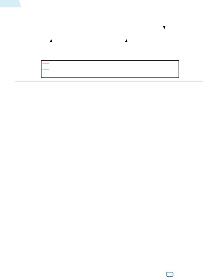
3.The Video Data Packet and Control Data Packet pair with changed width of 320 propagates through the Frame Buffer. The Control Synchronizer detects the change and triggers a write to the Scaler. The Control Synchronizer stalls the video processing pipeline while it performs the write.
Figure 11-3: Test Pattern Generator Change
|
|
|
|
|
|
|
Control Synchronizer Writes the Data to the |
||||||
|
|
|
|
|
|
|
Specified Addresses. This Configures the |
||||||
|
|
|
|
|
|
|
|
|
Scaler to an Output Width of |
320 |
|||
|
|
|
|
|
|
Avalon MM |
|
|
Avalon MM |
||||
|
|
|
|
|
|
|
Master |
|
|
|
|||
|
Test Pattern |
|
Frame |
|
Control |
|
Scaler |
|
|||||
|
Generator |
|
Buffer |
|
Synchronizer |
|
|
||||||
|
|
|
|
|
|
|
|||||||
Avalon |
MM |
|
|
|
|
|
|
Avalon |
MM |
|
|
|
|
|
|
|
|
|
|
|
|
||||||
|
|
|
|
|
|
|
|
|
|
|
|
|
|
|
|
|
|
|
Nios II CPU |
|
|
|
|
|
|
|
|
|
|
|
|
|
|
|
|
|
|
|
|
|
|
|
|
|
|
|
|
|
|
|
|
|
|
|
|
Red Line Indicates Control Data Packet and Video Data Packet Pair Number 14 (Width 320)
Blue Line Indicates Control Data Packet and Video Data Packet Pair Number 5 (Width 320)
Light Blue Line Indicates Control Data Packet and Video Data Packet Pair Number 4 (Width 640)
Control Data Packet and Video Data Packet Pair Numbers 6 to 13 are Stored in the Frame Buffer
4.The Scaler is reconfigured to output width 320 frames. The Control Synchronizer resumes the video processing pipeline. The scaling ratio maintains at 1:1.
Control Synchronizer IP Core |
Altera Corporation |
|
|
Send Feedback
11-4 |
Control Synchronizer Parameter Settings |
|
|
|
|
|
|
|
|
UG-VIPSUITE |
||||||
|
|
|
|
|
2015.01.23 |
|||||||||||
|
|
|
|
|
|
|
|
|
|
|
|
|||||
|
Figure 11-4: Reconfigured Scaler II |
|
|
|
|
|
|
|
|
|
|
|
||||
|
|
|
|
|
|
|
|
|
|
|
|
|
|
|||
|
|
|
|
|
|
|
Avalon MM |
|
|
|
Avalon MM |
|||||
|
|
|
|
|
|
|
|
|
|
|||||||
|
|
|
|
|
|
|
|
Master |
|
|
|
|||||
|
|
Test Pattern |
|
Frame |
|
Control |
|
Scaler |
|
|
|
|||||
|
Avalon |
Generator |
|
Buffer |
|
Synchronizer |
MM |
|
|
|
||||||
|
|
|
|
|
|
|
|
|||||||||
|
MM |
|
|
|
|
|
|
Avalon |
|
|
|
|
|
|||
|
|
|
|
|
|
|
|
|
|
|
||||||
|
|
|
|
|
|
Nios II CPU |
|
|
|
|
|
|
|
|
|
|
|
|
|
|
|
|
|
|
|
|
|
|
|
|
|
|
|
|
|
|
|
|
|
|
|
|
|
|
|
|
|
|
|
|
Red Line Indicates Control Data Packet and Video Data Packet Pair Number 14 (Width 320)
Blue Line Indicates Control Data Packet and Video Data Packet Pair Number 5 (Width 320)
Control Data Packet and Video Data Packet Pair Numbers 6 to 13 are Stored in the Frame Buffer
Control Synchronizer Parameter Settings
Table 11-1: Control Synchronizer Parameter Settings
Parameter |
|
Value |
|
Description |
|
|
|
|
|
Bits per pixel per color plane |
|
4-20, Default = 8 |
|
Select the number of bits per pixel (per color |
|
|
|
|
plane). |
|
|
|
|
|
Number of color planes |
|
1–4, Default = 3 |
|
Select the number of color planes that are |
|
|
|
|
sent over one data connection. For example, a |
|
|
|
|
value of 3 for R'G'B' R'G'B' R'G'B' in serial. |
Color planes are in parallel |
|
On or Off |
|
• Turn on to set colors planes in parallel. |
|
|
|
|
• Turn off to set colors planes in series. |
|
|
|
|
|
Trigger on width change |
|
On or Off |
|
Turn on to start transfer of control data when |
|
|
|
|
there is a change in width value. |
Trigger on height change |
|
On or Off |
|
Turn on to start transfer of control data when |
|
|
|
|
there is a change in height value. |
|
|
|
|
|
Trigger on start of video data |
|
On or Off |
|
Turn on to start transfer of control data when |
packet |
|
|
|
the core receives the start of video data |
|
|
|
|
packet. |
Require trigger reset via control |
|
On or Off |
|
Turn on to disable the trigger once triggered. |
port |
|
|
|
If you turn on this parameter, you need to |
|
|
|
|
enable the trigger using the control port. |
|
|
|
|
|
Maximum number of control |
|
1–10, Default = 3 |
|
Specify the maximum number of control data |
data entries |
|
|
|
entries that can be written to other cores. |
|
|
|
|
|
Altera Corporation |
Control Synchronizer IP Core |
|
|
Send Feedback