- •Contents
- •1. Video and Image Processing Suite Overview
- •Release Information
- •Device Family Support
- •Latency
- •In-System Performance and Resource Guidance
- •Stall Behavior and Error Recovery
- •2. Interfaces
- •Video Formats
- •Avalon-ST Video Protocol
- •Video Data Packets
- •Static Parameters of Video Data Packets
- •Control Data Packets
- •Ancillary Data Packets
- •User-Defined and Altera-Reserved Packets
- •Packet Propagation
- •Transmission of Avalon-ST Video Over Avalon-ST Interfaces
- •Packet Transfer Examples
- •Avalon-MM Slave Interfaces
- •Specification of the Type of Avalon-MM Slave Interfaces
- •Avalon-MM Master Interfaces
- •Specification of the Type of Avalon-MM Master Interfaces
- •Buffering of Non-Image Data Packets in Memory
- •3. Getting Started
- •IP Catalog and Parameter Editor
- •Specifying IP Core Parameters and Options
- •Installing and Licensing IP Cores
- •OpenCore Plus IP Evaluation
- •4. Clocked Video Interface IP Cores
- •Control Port
- •Clocked Video Input Format Detection
- •Interrupts
- •Clocked Video Output Video Modes
- •Interrupts
- •Generator Lock
- •Underflow and Overflow
- •Timing Constraints
- •Handling Ancillary Packets
- •Modules for Clocked Video Input II IP Core
- •Clocked Video Interface Parameter Settings
- •Clocked Video Interface Signals
- •Clocked Video Interface Control Registers
- •5. 2D FIR Filter IP Core
- •Calculation Precision
- •Coefficient Precision
- •Result to Output Data Type Conversion
- •2D FIR IP Core Parameter Settings
- •2D FIR Filter Signals
- •2D FIR Filter Control Registers
- •6. Video Mixing IP Cores
- •Alpha Blending
- •Video Mixing Parameter Settings
- •Video Mixing Signals
- •Video Mixing Control Registers
- •7. Chroma Resampler IP Core
- •Horizontal Resampling (4:2:2)
- •Vertical Resampling (4:2:0)
- •Chroma Resampler Parameter Settings
- •Chroma Resampler Signals
- •8. Video Clipping IP Cores
- •Video Clipping Parameter Settings
- •Video Clipping Signals
- •Video Clipping Control Registers
- •9. Color Plane Sequencer IP Core
- •Combining Color Patterns
- •Rearranging Color Patterns
- •Splitting and Duplicating
- •Subsampled Data
- •Color Plane Sequencer Parameter Settings
- •Color Plane Sequencer Signals
- •10. Color Space Conversion IP Cores
- •Input and Output Data Types
- •Color Space Conversion
- •Result of Output Data Type Conversion
- •Color Space Conversion Parameter Settings
- •Color Space Conversion Signals
- •Color Space Conversion Control Registers
- •11. Control Synchronizer IP Core
- •Using the Control Synchronizer IP Core
- •Control Synchronizer Parameter Settings
- •Control Synchronizer Signals
- •Control Synchronizer Control Registers
- •12. Deinterlacing IP Cores
- •Deinterlacing Methods
- •Bob with Scanline Duplication
- •Bob with Scanline Interpolation
- •Weave
- •Motion-Adaptive
- •Sobel-Based HQ Mode
- •Pass-Through Mode for Progressive Frames
- •Frame Buffering
- •Frame Rate Conversion
- •Bandwidth Requirement Calculations for 10-bit YCbCr Video
- •Behavior When Unexpected Fields are Received
- •Handling of Avalon-ST Video Control Packets
- •Deinterlacing Parameter Settings
- •Deinterlacing Signals
- •Deinterlacing Control Registers
- •Design Guidelines for Broadcast Deinterlacer IP Core
- •13. Frame Reader IP Core
- •Single-Cycle Color Patterns
- •Frame Reader Output Pattern and Memory Organization
- •Frame Reader Parameter Settings
- •Frame Reader Signals
- •Frame Reader Control Registers
- •14. Frame Buffer IP Cores
- •Double Buffering
- •Triple Buffering
- •Locked Frame Rate Conversion
- •Handling of Avalon-ST Video Control Packets
- •Color Format
- •Frame Buffer Parameter Settings
- •Frame Buffer Signals
- •Frame Buffer Control Registers
- •15. Gamma Corrector IP Core
- •Gamma Corrector Parameter Settings
- •Gamma Corrector Signals
- •Gamma Corrector Control Registers
- •16. Interlacer IP Core
- •Interlacer Parameter Settings
- •Interlacer Signals
- •Interlacer Control Registers
- •17. Scaler II IP Core
- •Nearest Neighbor Algorithm
- •Bilinear Algorithm
- •Bilinear Algorithmic Description
- •Polyphase and Bicubic Algorithm
- •Double-Buffering
- •Polyphase Algorithmic Description
- •Choosing and Loading Coefficients
- •Edge-Adaptive Scaling Algorithm
- •Scaler II Parameter Settings
- •Scaler II Signals
- •Scaler II Control Registers
- •18. Video Switching IP Cores
- •Mixer Layer Switching
- •Video Switching Parameter Settings
- •Video Switching Signals
- •Video Switching Control Registers
- •19. Test Pattern Generator IP Cores
- •Test Pattern
- •Generation of Avalon-ST Video Control Packets and Run-Time Control
- •Test Pattern Generator Parameter Settings
- •Test Pattern Generator Signals
- •Test Pattern Generator Control Registers
- •20. Trace System IP Core
- •Trace System Parameter Settings
- •Trace System Signals
- •Operating the Trace System from System Console
- •Loading the Project and Connecting to the Hardware
- •Trace Within System Console
- •TCL Shell Commands
- •21. Avalon-ST Video Monitor IP Core
- •Packet Visualization
- •Monitor Settings
- •Avalon-ST Video Monitor Parameter Settings
- •Avalon-ST Video Monitor Signals
- •Avalon-ST Video Monitor Control Registers
- •Avalon-ST Video Class Library
- •Running the Tests
- •Video File Reader Test
- •Example Test Environment
- •Video Field Life Cycle
- •Constrained Random Test
- •Complete Class Reference
- •c_av_st_video_control
- •c_av_st_video_data
- •c_av_st_video_file_io
- •c_av_st_video_item
- •c_av_st_video_source_sink_base
- •c_av_st_video_sink_bfm_’SINK
- •c_av_st_video_source_bfm_’SOURCE
- •c_av_st_video_user_packet
- •c_pixel
- •Raw Video Data Format
- •Cadence Detection and Reverse Pulldown in the Deinterlacer II IP Core
- •Document Revision History
- •How to Contact Altera
UG-VIPSUITE |
Interrupts |
4-5 |
|
2015.01.23 |
|||
|
|
Interrupts
The CVI IP cores produce a single interrupt line.
Table 4-5: Internal Interrupts
The table below lists the internal interrupts of the interrupt line.
IP Core |
|
Internal Interrupts |
|
Description |
|
|
|
|
|
|
|
Status update interrupt |
|
Triggers when a change of resolution in the |
|
|
|
|
incoming video is detected. |
|
|
|
|
|
|
|
Stable video interrupt |
|
• Triggers when the incoming video is |
|
|
|
|
detected as stable (has a consistent sample |
Clocked Video Input IP core |
|
|
|
length in two of the last three lines) or |
|
|
|
unstable (if, for example, the video cable is |
|
|
|
|
|
|
|
|
|
|
removed). |
|
|
|
|
• The incoming video is always detected as |
|
|
|
|
unstable when the vid_locked signal is |
|
|
|
|
low. |
|
|
|
|
|
|
|
Status update interrupt |
|
Triggers when the stable bit, the vid locked |
|
|
|
|
bit or the resolution valid bit of the Status |
|
|
|
|
register changes value. |
|
|
|
|
|
|
|
End of field/frame |
|
• If the synchronization settings are set to |
|
|
interrupt |
|
Any field first, triggers on the falling edge |
|
|
|
|
of the v sync. |
Clocked Video Input II IP core |
|
|
|
• If the synchronization settings are set to |
|
|
|
|
F1 first, triggers on the falling edge of the |
|
|
|
|
F1 v sync. |
|
|
|
|
• If the synchronization settings are set to |
|
|
|
|
F0 first, you can use the interrupt to |
|
|
|
|
trigger the reading of the ancillary packets |
|
|
|
|
from the control interface before they are |
|
|
|
|
overwritten by the next frame. |
|
|
|
|
|
These interrupts can be independently enabled using bits [2:1] of the Control register. Their values can be read using bits [2:1] of the Interrupt register. Writing 1 to either of these bits clears the respective interrupt.
Clocked Video Output Video Modes
The video frame is described using the mode registers that are accessed through the Avalon-MM control port.
If you turn off Use control port in the parameter editor for the CVO IP cores, then the output video format always has the format specified in the parameter editor.
Clocked Video Interface IP Cores |
Altera Corporation |
|
|
Send Feedback
4-6 |
Clocked Video Output Video Modes |
UG-VIPSUITE |
|
2015.01.23 |
|||
|
|
The CVO IP cores can be configured to support between 1 to 14 different modes and each mode has a bank of registers that describe the output frame.
• Clocked Video Output IP Core
•When the IP core receives a new control packet on the Avalon-ST Video input, it searches the mode registers for a mode that is valid. The valid mode must have a field width and height that matches the width and height in the control packet.
• The Video Mode Match register shows the selected mode.
•If a matching mode is found, it restarts the video output with those format settings.
•If a matching mode is not found, the video output format is unchanged and a restart does not occur.
•Clocked Video Output II IP Core
•When the IP core receives a new control packet on the Avalon-ST Video input, it searches the mode registers for a mode that is valid. The valid mode must have a field width and height that matches the width and height in the control packet.
• The Video Mode Match register shows the selected mode.
•If a matching mode is found, it completes the current frame; duplicating data if needed before commencing output with the new settings at the beginning of the next frame.
•If a matching mode is not found, the video output format is unchanged.
Altera Corporation |
Clocked Video Interface IP Cores |
|
|
Send Feedback
UG-VIPSUITE |
Clocked Video Output Video Modes |
4-7 |
|
2015.01.23 |
|||
|
|
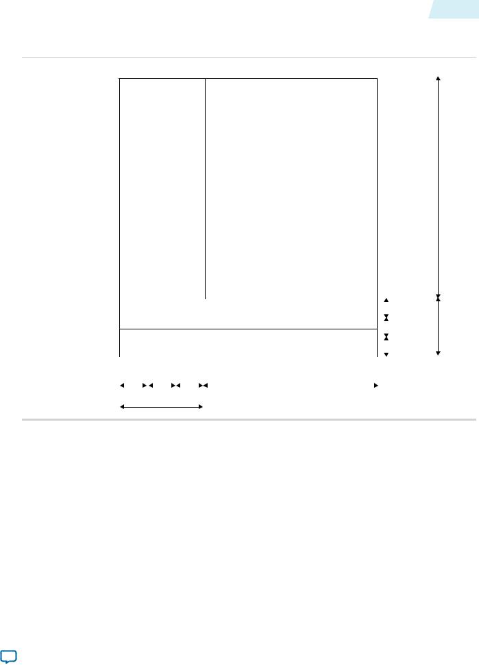
Figure 4-1: Progressive Frame Parameters
The figure shows how the register values map to the progressive frame format.
Active picture line
F0 active picture
|
|
|
|
|
|
|
|
V front |
|
|
|
|
|
|
|
||
|
|
|
|
|
|
|
|
|
|
|
|
|
|
|
|
|
porch |
|
|
|
|
|
|
|
|
|
Ancillary line |
|
|
|
|
|
|
V sync |
|
|
|
|
|
|
|
|||
|
|
|
|
|
|
|
|
V back |
|
|
|
|
|
|
|
|
|
|
|
|
|
|
|
|
|
porch |
|
|
|
|
|
|
|
|
|
|
H front |
H |
H back |
|
Active samples |
|
||
|
porch |
sync |
porch |
|
H blanking
Active lines
V blanking
Clocked Video Interface IP Cores |
Altera Corporation |
|
|
Send Feedback
4-8 Clocked Video Output Video Modes
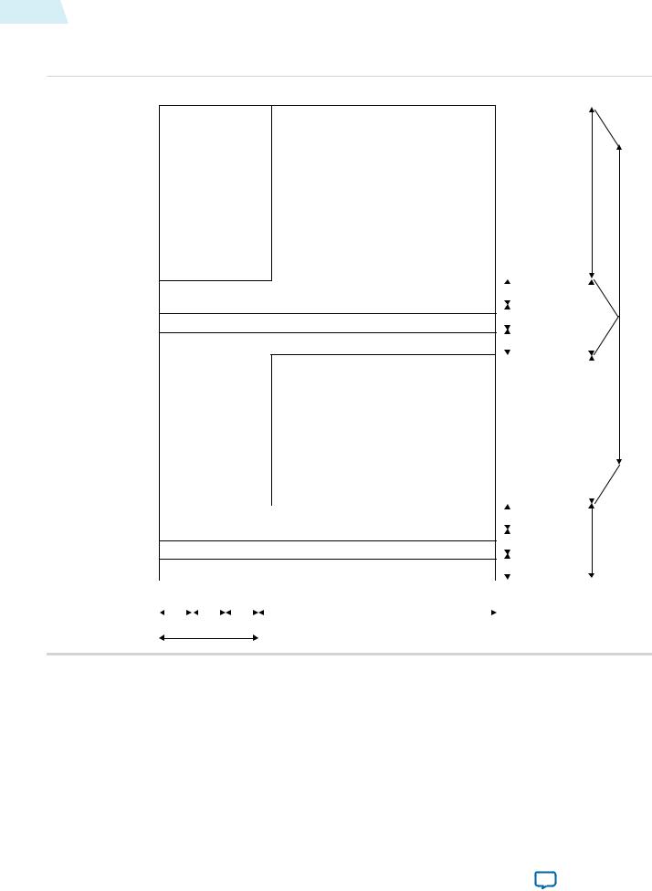
Figure 4-2: Interlaced Frame Parameters
The figure shows how the register values map to the interlaced frame format.
Active picture line
F0 active picture
F0 V rising |
|
|
|
edge line |
|
|
F0 V front |
|
|
||
|
|
|
|
F rising |
|
|
porch |
|
|
||
edge line |
|
|
F0 V sync |
|
|
||
F0 ancillary line |
|
|
|
|
|
F0 V back |
|
|
|
||
|
|
|
porch |
|
|
|
F1 active picture
|
|
|
|
|
|
|
|
V front |
|
|
|
|
|
|
|
||
|
|
|
|
|
|
|
|
|
F falling |
|
|
|
|
|
|
porch |
|
|
|
|
|
|
|
|||
edge line |
|
|
|
|
|
|
V sync |
|
|
|
|
|
|
|
|||
Ancillary line |
|
|
|
|
|
|
V back |
|
|
|
|
|
|
|
|||
|
|
|
|
|
|
|
|
porch |
|
|
|
|
|
|
|
|
|
|
H front |
H |
H back |
Active samples |
|
|||
|
porch |
sync |
porch |
|
H blanking
UG-VIPSUITE 2015.01.23
F0 active lines
F0 V blank |
Active lines |
|
|
F1 active lines |
|
|
|
|
|
V blanking
The mode registers can only be written to if a mode is marked as invalid.
Altera Corporation |
Clocked Video Interface IP Cores |
|
|
Send Feedback