


UG-VIPSUITE |
|
|
|
|
|
|
|
|
|
Ancillary Data Packets |
2-19 |
|||
2015.01.23 |
|
|
|
|
|
|
|
|
|
|
||||
|
|
|
|
|
|
|
|
|
|
|
|
|
||
|
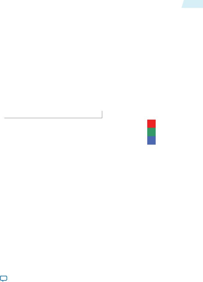
Figure 2-15: One Symbol in Parallel |
|
|
|
|
|
|
|
|
|
|
|
|
|
|
|
|
|
|
|
|
|
|||||||
|
Start |
|
Control data, reference numbers to Table 4-5 |
|
End |
|
||||||||
|
|
|
|
|
|
|
|
|
|
|
|
|||
|
|
|
|
|
|
|
|
|
|
|
|
|
|
|
|
|
15 |
1 |
|
2 |
3 |
4 |
5 |
6 |
7 |
8 |
9 |
|
|
|
|
|
|
|
|
|
|
|
|
|
|
|
|
|
Control data packet type identifier (4 bits in least significant symbol, X’s for unused symbols)
Ancillary Data Packets
Ancillary data packets send ancillary packets between IP cores.
Ancillary data packets are typically placed between a control data packet and a video data packet and contain information that describes the video data packet, for example active format description codes.
An ancillary data packet can contain one or more ancillary packets, each ancillary packet starts with the hexadecimal code 0, 3FF, 3FF.
Note: The format of ancillary packets is defined in the SMPTE S291M standard.
IP cores are not required to understand or process ancillary data packets, but must forward them on, as is done with user-defined and Altera-reserved packets.
User-Defined and Altera-Reserved Packets
The Avalon-ST Video protocol specifies seven packet types reserved for use by users and five packet types reserved for future use by Altera.
The data content of all of these packets is undefined. However the structure must follow the rule that the packets are split into symbols as defined by the number color plane samples sent in one cycle of the color pattern.
Unlike control data packets, user packets are not restricted to four bits of data per symbol. However when a core reduces the bits per pixel per color plane (and thus the bit width of the symbols) to less than the number of bits in use per symbol, data is lost.
Packet Propagation
The Avalon-ST Video protocol is optimized for the transfer of video data while still providing a flexible way to transfer control data and other information.
Interfaces |
Altera Corporation |
|
|
Send Feedback

2-20 |
Transmission of Avalon-ST Video Over Avalon-ST Interfaces |
UG-VIPSUITE |
|
2015.01.23 |
|||
|
|
To make the protocol flexible and extensible, the Video and Image Processing IP cores obey the following rules about propagating non-video packets:
•IP cores must propagate user packets until their end of packet signal is received. Nevertheless, IP cores that buffer packets into external memory might introduce a maximum size due to limited storage space.
•IP cores can propagate control packets or modify them on the fly. IP cores can also cancel a control packet by following it with a new control packet.
•When the bits per color sample change from the input to the output side of a IP core, the non-video packets are truncated or padded. Otherwise, the full bit width is transferred.
•IP cores that can change the color pattern of a video data packets may also pad non-video data packets with extra data. When defining a packet type where the length is variable and meaningful, it is recommended to send the length at the start of the packet.
Transmission of Avalon-ST Video Over Avalon-ST Interfaces
Avalon-ST Video is a protocol transmitted over Avalon-ST interfaces.
Table 2-8: Avalon-ST Interface Parameters
The table below lists the values of these parameters that are defined for transmission of the Avalon-ST Video protocol. All parameters not explicitly listed in the table have undefined values.
Parameter Name |
|
Value |
|
|
|
BITS_PER_SYMBOL |
|
Variable. Always equal to the Bits per Color Sample parameter value of |
|
|
the stream of pixel data being transferred. |
|
|
|
PIXELS_IN_PARALLEL |
|
Variable. Always equal to the number of pixels transferred in parallel. |
|
|
Note: Only aligned pixels supported of frame/line size module |
|
|
pixels in parallel. |
|
|
|
SYMBOLS_PER_BEAT |
|
Variable. Always equal to the number of color samples being |
|
|
transferred in parallel. This is equivalent to the number of rows in the |
|
|
color pattern parameter value of the stream of pixel data being |
|
|
transferred. |
|
|
|
READY_LATENCY |
|
1 |
|
|
|
Table 2-9: Avalon-ST Interface Signal Types
The table below lists the signals for transmitting Avalon-ST Video. The unused signals are not listed.
|
|
Signal |
|
Width |
|
Direction |
|
|
|
|
|
|
|
|
|
|
ready |
|
1 |
|
Sink to Source |
||
|
|
|
|
|
|
|
|
|
valid |
|
1 |
|
Source to Sink |
|
|
|
|
|
|
|
|
|
|
|
data |
|
bits_per_symbol × symbols_per_beat × |
|
Source to Sink |
||
|
|
|
|
pixels_in_parallel |
|
|
|
|
|
|
|
|
|
|
|
|
empty |
|
1–8 |
|
Source to Sink |
|
|
|
|
|
|
|
|
|
|
|
startofpacket |
|
1 |
|
Source to Sink |
||
|
|
|
|
|
|
|
|
|
|
|
|
|
|||
Altera Corporation |
|
|
|
|
Interfaces |
||
|
|
|
|
|
|
Send Feedback |
|
UG-VIPSUITE |
|
|
Packet Transfer Examples |
2-21 |
||
2015.01.23 |
|
|
||||
|
|
|
|
|
||
|
|
|
|
|
|
|
|
Signal |
|
Width |
|
Direction |
|
|
|
|
|
|
|
|
|
endofpacket |
|
1 |
|
Source to Sink |
|
|
|
|
|
|
|
|
Related Information
Avalon Interface Specifications
Packet Transfer Examples
All packets are transferred using the Avalon-ST signals in the same way.
Example 1 (Data Transferred in Parallel)
This example shows the transfer of a video data packet in to and then out of a generic IP core that supports the Avalon-ST Video protocol.
In this case, both the input and output video data packets have a parallel color pattern and eight bits per pixel per color plane.
Table 2-10: Parameters for Example of Data Transferred in Parallel
Parameter |
|
Value |
|
|
|
Bits per Pixel per Color Plane |
8 |
|
|
R |
|
|
|
|
Color Pattern |
G |
|
|
|
|
|
B |
|
|
|
|
|
|
|
Interfaces |
Altera Corporation |
|
|
Send Feedback

2-22 |
Packet Transfer Examples |
UG-VIPSUITE |
|
2015.01.23 |
|||
|
|
Figure 2-16: Timing Diagram Showing R’G’B’ Transferred in Parallel
The figure below shows how the first few pixels of a frame are processed.
|
1. |
2. |
3. |
4. |
5. |
6. |
7. |
|
|
|
|
|
|
|
n. |
|
||||||||||||||
|
|
|
|
|
|
|
|
|
|
|
|
|
|
|
|
|
|
|
|
|
|
|
|
|
|
|
|
|
|
|
|
clock |
|
|
|
|
|
|
|
|
|
|
|
|
|
|
|
|
|
|
|
|
|
|
|
|
|
|
|||
|
|
|
|
|
|
|
|
|
|
|
|
|
|
|
|
|
|
|
|
|
|
|
|
|
|
|
|
|
|
|
din_ready |
|
|
|
|
|
|
|
|
|
|
|
|
|
|
|
|
|
|
|
|
|
|
|
|
|
|||||
|
|
|
|
|
|
|
|
|
|
|
|
|
|
|
|
|
|
|
|
|
|
|
|
|
||||||
|
|
|
|
|
|
|
|
|
|
|
|
|
|
|
|
|
|
|
|
|
|
|
|
|
|
|
|
|
|
|
din_valid |
|
|
|
|
|
|
|
|
|
|
|
|
|
|
|
|
|
|
|
|
|
|
|
|
|
|
||||
|
|
|
|
|
|
|
|
|
|
|
|
|
|
|
|
|
|
|
|
|
|
|
|
|
||||||
din_startofpacket |
|
|
|
|
|
|
|
|
|
|
|
|
|
|
|
|
|
|
|
|
|
|
|
|
|
|||||
|
|
|
|
|
|
|
|
|
|
|
|
|
|
|
|
|
|
|
|
|
|
|
|
|
||||||
|
|
|
|
|
|
|
|
|
|
|
|
|
|
|
|
|
|
|
|
|
|
|
|
|
|
|
|
|||
din_endofpacket |
|
|
|
|
|
|
|
|
|
|
|
|
|
|
|
|
|
|
|
|
|
|
|
|
|
|||||
|
|
|
|
|
|
|
|
|
|
|
|
|
|
|
|
|
|
|
|
|
|
|
|
|
||||||
|
|
|
|
|
|
|
|
|
|
|
|
|
|
|
|
|
|
|
|
|
|
|
|
|
|
|
|
|
|
|
|
23:16 |
|
|
|
|
|
|
|
|
X |
|
R 0,0 |
|
|
|
R 1,0 |
|
B 2,0 |
|
|
|
|
|
R x,y |
|
|||||
din_data |
15:8 |
|
|
|
|
|
|
|
|
X |
|
G 0,0 |
|
|
|
G 1,0 |
|
G 2,0 |
|
|
|
|
|
G x,y |
|
|||||
|
7:0 |
|
|
|
|
|
|
|
|
0 |
|
B 0,0 |
|
|
|
B 1,0 |
|
B 2,0 |
|
|
|
|
|
B x,y |
|
|||||
|
|
|
|
|
|
|
|
|
|
|
|
|
|
|
|
|
|
|
|
|
|
|
|
|
|
|
|
|
|
|
dout_ready |
|
|
|
|
|
|
|
|
|
|
|
|
|
|
|
|
|
|
|
|
|
|
|
|
|
|||||
dout_valid |
|
|
|
|
|
|
|
|
|
|
|
|
|
|
|
|
|
|
|
|
|
|
|
|
|
|
||||
|
|
|
|
|
|
|
|
|
|
|
|
|
|
|
|
|
|
|
|
|
|
|
|
|
||||||
dout_startofpacket |
|
|
|
|
|
|
|
|
|
|
|
|
|
|
|
|
|
|
|
|
|
|
|
|
|
|||||
|
|
|
|
|
|
|
|
|
|
|
|
|
|
|
|
|
|
|
|
|
|
|
|
|
||||||
|
|
|
|
|
|
|
|
|
|
|
|
|
|
|
|
|
|
|
|
|
|
|
|
|
|
|
||||
dout_endofpacket |
|
|
|
|
|
|
|
|
|
|
|
|
|
|
|
|
|
|
|
|
|
|
|
|
|
|
||||
|
|
|
|
|
|
|
|
|
|
|
|
|
|
|
|
|
|
|
|
|
|
|
|
|
|
|
|
|||
|
23:16 |
|
|
|
|
|
|
|
|
|
|
|
|
|
|
|
|
X |
|
R 0,0 |
|
|
|
|
|
|
||||
dout_data |
15:8 |
|
|
|
|
|
|
|
|
|
|
|
|
|
|
|
|
X |
|
G 0,0 |
|
|
|
|
|
|
|
|
||
|
7:0 |
|
|
|
|
|
|
|
|
|
|
|
|
|
|
|
|
0 |
|
B 0,0 |
|
|
|
|
|
|
|
|
||
|
|
|
|
|
|
|
|
|
|
|
|
|
|
|
|
|
|
|
|
|
|
|
|
|
|
|
|
|
|
|
This example has one Avalon-ST port named din and one Avalon-ST port named dout. Data flows into the IP core through din, is processed and flows out of the IP core through dout.
There are five signals types—ready, valid, data, startofpacket, and endofpacket—associated with each port. The din_ready signal is an output from the IP core and indicates when the input port is ready to receive data. The din_valid and din_data signals are both inputs. The source connected to the input port sets din_valid to logic '1' when din_data has useful information that must be sampled. The din_startofpacket signal is an input that is raised to indicate the start of a packet, with din_endofpacket signaling the end of a packet. The five output port signals have equivalent but opposite semantics.
The sequence of events for this example:
1.Initially, din_ready is logic '0', indicating that the IP core is not ready to receive data on the next cycle. Many of the Video and Image Processing Suite IP cores are not ready for a few clock cycles in between rows of image data or in between video frames.
2.The IP core sets din_ready to logic '1', indicating that the input port is ready to receive data one clock cycle later. The number of clock cycles of delay which must be applied to a ready signal is referred to as
Altera Corporation |
Interfaces |
|
|
Send Feedback

UG-VIPSUITE |
Packet Transfer Examples |
2-23 |
|
2015.01.23 |
|||
|
|
ready latency in the Avalon Interface Specifications. All of the Avalon-ST interfaces that the Video and Image Processing Suite IP cores use have a ready latency of one clock cycle.
3.The source feeding the input port sets din_valid to logic '1' indicating that it is sending data on the data port and sets din_startofpacket to logic '1' indicating that the data is the first value of a new packet. The data is 0, indicating that the packet is video data.
4.The source feeding the input port holds din_valid at logic '1' and drops din_startofpacket indicating that it is now sending the body of the packet. It puts all three color values of the top left pixel of the frame on to din_data.
5.No data is transmitted for a cycle even though din_ready was logic '1' during the previous clock cycle and therefore the input port is still asserting that it is ready for data. This could be because the source has no data to transfer. For example, if the source is a FIFO, it could have become empty.
6.Data transmission resumes on the input port: din_valid transitions to logic '1' and the second pixel is transferred on din_data. Simultaneously, the IP core begins transferring data on the output port. The example IP core has an internal latency of three clock cycles so the first output is transferred three cycles after being received. This output is the type identifier for a video packet being passed along the datapath.
7.The third pixel is input and the first processed pixel is output.
8.For the final sample of a frame, the source sets din_endofpacket to logic '1', din_valid to '1', and puts the bottom-right pixel of the frame on to din_data.
Example 2 (Data Transferred in Sequence)
This example shows how a number of pixels from the middle of a frame could be processed by another IP core. This time handling a color pattern that has planes B'G'R' in sequence. This example does not show the start of packet and end of packet signals because these are always low during the middle of a packet.
Table 2-11: Parameters for Example of Data Transferred in Sequence
The table below lists the bits per pixel per color plane and color pattern.
Parameter |
|
|
|
Value |
|
|
|
|
|
|
|
|
|
|
|
Bits per Color Sample |
|
|
|
8 |
|
|
|
|
|
|
|
|
|
|
|
Color Pattern |
|
|
|
|
|
|
|
|
|
B |
|
G |
R |
|
|
|
|
|
|
|
|||
|
|
|
|
|
|
|
|
|
|
|
|
|
|
|
|
Interfaces |
Altera Corporation |
|
|
Send Feedback
2-24 |
Packet Transfer Examples |
UG-VIPSUITE |
|
2015.01.23 |
|||
|
|
Figure 2-17: Timing Diagram Showing R’G’B’ Transferred in Sequence
The figure shows how a number of pixels from the middle of a frame are processed.
|
|
|
|
1. |
|
2. |
|
3. |
|
4. |
|
5. |
|
6. |
7. |
8. |
|
9. |
|
|
||
clock |
|
|
|
|
|
|
|
|
|
|
|
|
|
|
|
|
|
|
|
|||
|
|
|
|
|
|
|
|
|
|
|
|
|
|
|
|
|
|
|
||||
|
|
|
|
|
|
|
|
|
|
|
|
|
|
|
|
|
|
|
|
|
|
|
din_ready |
|
|
|
|
|
|
|
|
|
|
|
|
|
|
|
|
|
|
|
|||
din_valid |
|
|
|
|
|
|
|
|
|
|
|
|
|
|
|
|
|
|
|
|
||
|
|
|
|
|
|
|
|
|
|
|
|
|
|
|
|
|
|
|
|
|||
|
|
|
|
|
|
|
|
|
|
|
|
|
|
|
|
|
||||||
din_data 7:0 |
B m,n |
G m,n |
R m,n |
B m+1,n |
G m+1,n |
|
|
|
|
|
|
R m+1,n |
|
|||||||||
|
|
|
|
|
|
|
|
|
|
|
|
|
|
|
|
|
|
|
|
|
|
|
dout_ready |
|
|
|
|
|
|
|
|
|
|
|
|
|
|
|
|
|
|
|
|||
dout_valid |
|
|
|
|
|
|
|
|
|
|
|
|
|
|
|
|
|
|
|
|||
|
|
|
|
|
|
|
|
|
|
|
|
|
|
|
|
|
|
|
||||
|
|
|
|
|
|
|
|
|
|
|
|
|
|
|
|
|
|
|
||||
|
|
|
|
|
|
|
|
|
|
|
|
|
|
|
|
|
|
|
|
|||
|
|
|
|
|
|
|
|
|
|
|
|
|
|
|
|
|
|
|
||||
dout_data 7:0 |
|
|
|
|
|
|
B m,n |
|
|
|
|
|
|
G m,n |
R m,n |
|
||||||
|
|
|
|
|
|
|
|
|
|
|
|
|
|
|
|
|
|
|
|
|
|
|
This example is similar to example one except that it is configured to accept data in sequence rather than parallel. The signals shown in the timing diagram are therefore the same but with the exception that the two data ports are only 8 bits wide.
The sequence of events for this example:
1.Initially, din_ready is logic '1'. The source driving the input port sets din_valid to logic '1' and puts the blue color value Bm,n on the din_data port.
2.The source holds din_valid at logic '1' and the green color value Gm,n is input.
3.The corresponding red color value Rm,n is input.
4.The IP core sets dout_valid to logic '1' and outputs the blue color value of the first processed color sample on the dout_data port. Simultaneously the sink connected to the output port sets dout_ready to logic '0'. The Avalon Interface Specifications state that sinks may set ready to logic '0' at any time, for example because the sink is a FIFO and it has become full.
5.The IP core sets dout_valid to logic '0' and stops putting data on the dout_data port because the sink is not ready for data. The IP core also sets din_ready to logic '0' because there is no way to output data and the IP core must stop the source from sending more data before it uses all internal buffer space.
The sink holds din_valid at logic '1' and transmits one more color sample Gm+1,n, which is legal because the ready latency of the interface means that the change in the IP core's readiness does not take effect for one clock cycle.
6.Both the input and output interfaces does not transfer any data: the IP core is stalled waiting for the sink.
7.The sink sets dout_ready to logic '1'. This could be because space has been cleared in a FIFO.
8.The IP core sets dout_valid to logic '1' and resumes transmitting data. Now that the flow of data is again unimpeded, it sets din_ready to logic '1'.
9.The source responds to din_ready by setting din_valid to logic '1' and resuming data transfer.
Altera Corporation |
Interfaces |
|
|
Send Feedback