

UG-VIPSUITE |
Control Data Packets |
2-15 |
|
2015.01.23 |
|||
|
|
Structure of Video Data Packets
Figure 2-11: Parallel Color Pattern
This figure shows the structure of a video data packet using a set parallel color pattern and bits per pixel per color plane.
Color |
R |
Bits per pixel |
Video Data, repeating a |
|
Pattern |
|
per color plane |
regular color pattern |
|
G |
||||
|
= 8 |
|||
|
|
|||
|
B |
|
|
Symbols on bits 23:16
Symbols on bits 15:8
Symbols on bits 7:0
Start
X |
R |
R |
R |
R |
R |
R |
R |
|
R |
R |
R |
|
|
|
|
|
|
|
|
|
|
|
|
X |
G |
G |
G |
G |
G |
G |
G |
|
G |
G |
G |
|
|
|
|
|
|
|
|
|
|
|
|
0 |
B |
B |
B |
B |
B |
B |
B |
|
B |
B |
B |
|
|
|
|
|
|
|
|
|
|
|
|
End
Video data packet type identifier (4 bits in least significant symbol, X’s for unused symbols)
Figure 2-12: Sequence Color Pattern
This figure shows the structure of a video data packet using a set sequential color pattern and bits per pixel per color plane.
Color |
B |
G |
R |
Bits per pixel |
|
|
|
|
|
|
|
|
|
||
Pattern |
per color plane |
|
Video Data, repeating a |
|
|
|
|
||||||||
|
|
|
|
|
|
|
|
||||||||
|
|
|
|
|
= 8 |
|
|
|
regular color pattern |
|
|
|
|
||
Symbols on bits 7:0 |
0 |
B |
G |
R |
B |
G |
R |
B |
G |
R |
B |
G |
R |
||
|
|
Start |
|
|
|
|
|
|
|
|
|
|
|
|
End |
|
Video data packet type identifier |
|
|
|
|
|
|
|
|
|
|
||||
|
(4 bits in least significant symbol, |
|
|
|
|
|
|
|
|
|
|
||||
|
|
X’s for unused symbols) |
|
|
|
|
|
|
|
|
|
|
|||
Note: Only aligned pixels supported of frame/line size modular pixels in parallel.
Control Data Packets
Control data packets configure the IP cores so that they correctly process the video data packets that follow.
In addition to a packet type identifier of value 15, control data packets contain these data:
•Width (16 bit)
•Height (16 bit)
•Interlacing (4 bit)
Interfaces |
Altera Corporation |
|
|
Send Feedback

2-16 |
Control Data Packets |
UG-VIPSUITE |
|
2015.01.23 |
|||
|
|
The width and height values are the dimensions of the video data packets that follow. The width refers to the width in pixels of the lines of a frame. The height refers the number of lines in a frame or field, such that a field of interlaced 1920×1080 (1080i) would have a width of 1920 and a height of 540, and a frame of 1920×1080 (1080p) would have a width of 1920 and a height of 1080.
When a video data packet uses a subsampled color pattern, the individual color planes of the video data packet have different dimensions. For example, 4:2:2 has one full width, full height plane and two half width, full height planes. For 4:2:0 there are one full width, full height plane and two half width, half height planes. In these cases you must configure the width and height fields of the control data packet for the fully sampled, full width, and full height plane.
The interlacing value in the control packet indicates whether the video data packets that follow contain progressing or interlaced video. The most significant two bits of the interlacing nibble describe whether the next video data packet is either progressive, interlaced field 0 (F0) containing lines 0, 2, 4.... or interlaced field 1 (F1) containing lines 1, 3, 5... 00 means progressive, 10 means interlaced F0, and 11 means interlaced F1.
The meaning of the second two bits is dependent on the first two bits. If the first two bits are set to 10 (F0) or 11 (F1), the second two bits describe the synchronization of interlaced data. Use the synchronization bits for progressive segmented frame (PsF) content, where progressive frames are transmitted as two interlaced fields.
Synchronizing on F0 means that a video frame should be constructed from an F1 followed by an F0. Similarly, synchronizing on F1 means that a video frame should be constructed from an F0 followed by an F1. The other synchronization options are don't care when there is no difference in combining an F1 then F0, or an F0 then F1. The final option is don't know to indicate that the synchronization of the interlaced fields is unknown. The encoding for these options are 00 for synchronize on F0, 01 for synchronize on F1, 11 for don't care, and 10 for don't know.
Note: The synchronization bits do not affect the behavior of the Deinterlacing IP cores because the synchronization field is fixed at compile time. However, they do affect the behavior of the Frame Buffer IP core when dropping and repeating pairs of fields.
If the first two bits indicate a progressive frame, the second two bits indicate the type of the last field that the progressive frame was deinterlaced from. The encoding for this is 10 for unknown or 11 for not deinterlaced, 00 for F0 last, and 01 for F1 last.
Table 2-7: Examples of Control Data Packet Parameters
|
|
|
|
Parameters |
|
|
|
|
|
|
||
|
|
|
|
|
|
|
|
|
|
|
Description |
|
|
Type |
|
Width |
|
|
Height |
|
Interlacin |
|
|
||
|
|
|
|
|
|
|
|
|||||
|
|
|
|
|
|
|
|
|
g |
|
|
|
|
|
|
|
|
|
|
|
|
|
|
|
|
15 |
|
|
1920 |
|
|
1080 |
|
0011 |
|
The frames that follow are progressive with a |
||
|
|
|
|
|
|
|
|
|
|
|
resolution of 1920×1080. |
|
|
|
|
|
|
|
|
|
|
|
|
||
|
15 |
|
|
640 |
|
|
480 |
|
0011 |
|
The frames that follow are progressive with a |
|
|
|
|
|
|
|
|
|
|
|
|
resolution of 640×480. |
|
|
15 |
|
|
640 |
|
|
480 |
|
0000 |
|
The frames that follow are progressive with a |
|
|
|
|
|
|
|
|
|
|
|
|
resolution of 640×480. The frames were deinterlaced |
|
|
|
|
|
|
|
|
|
|
|
|
using F0 as the last field. |
|
|
|
|
|
|
|
|
|
|
|
|
|
|
|
|
|
|
|
|
|
|
|
|
|||
Altera Corporation |
|
|
|
|
|
|
|
|
|
Interfaces |
||
|
|
|
|
|
|
|
|
|
|
|
Send Feedback |
|

UG-VIPSUITE |
|
|
|
|
|
|
|
|
Control Data Packets |
2-17 |
|
2015.01.23 |
|
|
|
|
|
|
|
|
|||
|
|
|
|
|
|
|
|
|
|
||
|
|
|
|
|
|
|
|
|
|
|
|
|
|
|
Parameters |
|
|
|
|
|
|
||
|
|
|
|
|
|
|
|
|
|
Description |
|
|
Type |
|
Width |
|
|
Height |
|
Interlacin |
|
|
|
|
|
|
|
|
|
|
|
||||
|
|
|
|
|
|
|
|
g |
|
|
|
|
|
|
|
|
|
|
|
|
|
|
|
|
15 |
|
640 |
|
|
480 |
|
0001 |
|
The frames that follow are progressive with a |
|
|
|
|
|
|
|
|
|
|
|
resolution of 640×480. The frames were deinterlaced |
|
|
|
|
|
|
|
|
|
|
|
using F1 as the last field. |
|
|
15 |
|
640 |
|
|
240 |
|
1000 |
|
The fields that follow are 640 pixels wide and 240 |
|
|
|
|
|
|
|
|
|
|
|
pixels high. The next field is F0 (even lines) and it is |
|
|
|
|
|
|
|
|
|
|
|
paired with the F1 field that precedes it. |
|
|
|
|
|
|
|
|
|
|
|
|
|
|
15 |
|
1920 |
|
|
540 |
|
1100 |
|
The fields that follow are 1920 pixels wide and 540 |
|
|
|
|
|
|
|
|
|
|
|
pixels high. The next field is F1 (odd lines) and it is |
|
|
|
|
|
|
|
|
|
|
|
paired with the F0 field that follows it. |
|
|
15 |
|
1920 |
|
|
540 |
|
1101 |
|
The fields that follow are 1920 pixels wide and 540 |
|
|
|
|
|
|
|
|
|
|
|
pixels high. The next field is F1 (odd lines) and it is |
|
|
|
|
|
|
|
|
|
|
|
paired with the F0 field that precedes it. |
|
|
|
|
|
|
|
|
|
|
|
|
|
|
15 |
|
1920 |
|
|
540 |
|
1011 |
|
The fields that follow are 1920 pixels wide and 540 |
|
|
|
|
|
|
|
|
|
|
|
pixels high. The next field is F0 (even lines) and you |
|
|
|
|
|
|
|
|
|
|
|
must handle the stream as genuine interlaced video |
|
|
|
|
|
|
|
|
|
|
|
material where the fields are all temporally disjoint. |
|
|
15 |
|
1920 |
|
|
540 |
|
1010 |
|
The fields that follow are 1920 pixels wide and 540 |
|
|
|
|
|
|
|
|
|
|
|
pixels high. The next field is F0 (even lines) and you |
|
|
|
|
|
|
|
|
|
|
|
must handle the stream as genuine interlaced video |
|
|
|
|
|
|
|
|
|
|
|
content although it may originate from a progressive |
|
|
|
|
|
|
|
|
|
|
|
source converted with a pull-down. |
|
|
|
|
|
|
|
|
|
|
|
|
|
Use of Control Data Packets
A control data packet must immediately precede every video data packet. To facilitate this, any IP function that generates control data packets must do so once before each video data packet. Additionally all other IP cores in the processing pipeline must either pass on a control data packet or generate a new one before each video data packet. If the function receives more than one control data packet before a video data packet, it uses the parameters from the last received control data packet. If the function receives a video data packet with no preceding control data packet, the current functions keep the settings from the last control data packet received, with the exception of the next interlaced field type—toggling between F0 and F1 for each new video data packet that it receives.
Note: This behavior may not be supported in future releases. Altera recommends for forward compati bility that functions implementing the protocol ensure there is a control data packet immediately preceding each video data packet.
Structure of a Control Data Packet
A control data packet complies with the standard of a packet type identifier followed by a data payload. The data payload is split into nibbles of 4 bits, each data nibble is part of a symbol. If the width of a symbol is greater than 4 bits, the function does not use the most significant bits of the symbol.
Interfaces |
Altera Corporation |
|
|
Send Feedback
2-18 |
Control Data Packets |
|
|
|
|
|
UG-VIPSUITE |
||
|
|
|
|
2015.01.23 |
|||||
|
|
|
|
|
|
|
|||
|
|
|
|
|
|
|
|
|
|
|
|
Order |
|
Symbol |
|
Order |
|
Symbol |
|
|
|
|
|
|
|
|
|
|
|
|
|
1 |
|
width[15..12] |
|
6 |
|
height[11..8] |
|
|
|
|
|
|
|
|
|
|
|
|
|
2 |
|
width[11..8] |
|
7 |
|
height[7..4] |
|
|
|
3 |
|
width[7..4] |
|
8 |
|
height[3..0] |
|
|
|
|
|
|
|
|
|
|
|
|
|
4 |
|
width[3..0] |
|
9 |
|
interlacing[3..0] |
|
|
|
5 |
|
height[15..12] |
|
— |
|
— |
|
|
|
|
|
|
|
|
|
|
|
If the number of symbols transmitted in one cycle of the Avalon-ST interface is more than one, then the nibbles are distributed such that the symbols occupying the least significant bits are populated first.
The following figures show examples of control data packets, and how they are split into symbols.
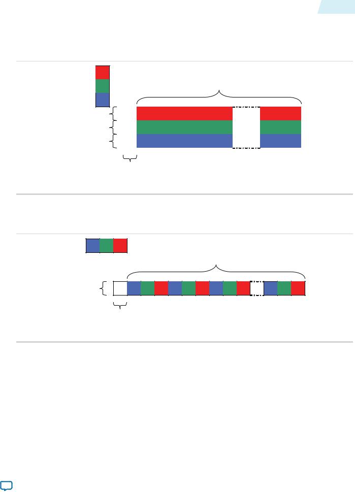
Figure 2-13: Three Symbols in Parallel
Control data, reference numbers to Table 4-5
Start |
|
|
|
End |
|
|
X |
3 |
6 |
9 |
Symbols in most significant bits |
|
|
|
|
|
Symbols in middle significant bits |
|
X |
2 |
5 |
8 |
|
|
|
|
|
|
Symbols in least significant bits |
|
15 |
1 |
4 |
7 |
|
|
|
|
|
|
|
Control data packet type identifier (4 bits in least significant symbol, X’s for unused symbols)
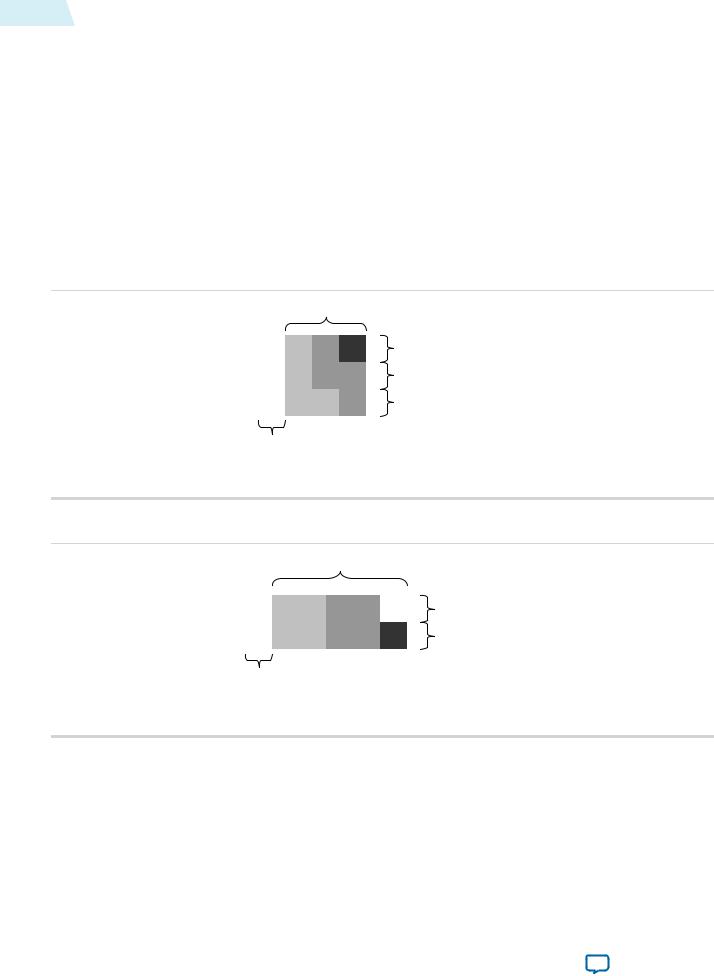
Figure 2-14: Two Symbols in Parallel
Control data, reference numbers to Table 4-5
Start |
|
|
|
|
|
End |
|
|
|
|
|
|
|
|
Symbols in most significant bits |
|
X |
2 |
4 |
6 |
8 |
X |
|
|
|
|
|
|
|
|
Symbols in least significant bits |
|
15 |
1 |
3 |
5 |
7 |
9 |
|
|
|
|
|
|
|
|
|
Control data packet type identifier (4 bits in least significant symbol, X’s for unused symbols)
Altera Corporation |
Interfaces |
|
|
Send Feedback