


UG-VIPSUITE |
|
|
|
Modules for Clocked Video Input II IP Core |
4-15 |
|
2015.01.23 |
|
|
|
|||
|
|
|
|
|
||
|
Table 4-8: AFD Inserter Register Map |
|
|
|
||
|
|
|
|
|
|
|
|
Address |
|
Register |
|
Description |
|
|
|
|
|
|
|
|
0 |
|
Control |
|
• When bit 0 is 0, the core discards all packets. |
|
|
|
|
|
|
|
• When bit 0 is 1, the core passes through all non-ancillary |
|
|
|
|
|
|
packets. |
|
|
|
|
|
|
|
|
|
1 |
|
— |
|
Reserved. |
|
|
2 |
|
— |
|
Reserved. |
|
|
|
|
|
|
|
|
|
3 |
|
AFD |
|
Bits 0-3 contain the active format description code. |
|
|
4 |
|
AR |
|
Bit 0 contains the aspect ratio code. |
|
|
|
|
|
|
|
|
|
5 |
|
Bar data flags |
|
Bits 0-3 contain the bar data flags to insert. |
|
|
6 |
|
Bar data value 1 |
|
Bits 0-15 contain bar data value 1 to insert. |
|
|
|
|
|
|
|
|
|
7 |
|
Bar data value 2 |
|
Bits 0-15 contain bar data value 2 to insert. |
|
|
8 |
|
AFD valid |
|
• When bit 0 is 0, an AFD packet is not present for each |
|
|
|
|
|
|
image packet. |
|
|
|
|
|
|
• When bit 0 is 1, an AFD packet is present for each image |
|
|
|
|
|
|
packet. |
|
|
|
|
|
|
|
|
Modules for Clocked Video Input II IP Core
The architecture for the Clocked Video Input II IP core differs from the existing Clocked Video Input IP core.
Clocked Video Interface IP Cores |
Altera Corporation |
|
|
Send Feedback
4-16 |
Modules for Clocked Video Input II IP Core |
UG-VIPSUITE |
|
2015.01.23 |
|||
|
|
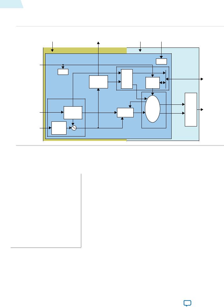
Figure 4-5: Block Diagram for Clocked Video Input II IP Core
The figure below shows a block diagram of the Clocked Video Input II IP core architecture.
|
sof |
|
|
vid_clk |
sof_locked |
ls_clk |
rst |
refclk_div |
|
Core |
|
|
|
|
|
Reset |
|
|
|
vid_locked |
|
|
|
|
|
|
|
|
|
|
|
|
|
|
|
|
|
|
|
|
|
|
Reset |
Auxiliary Packets |
|
|
Control |
|
|
|
||
|
|
|
|
|
|
|
|
|||
|
|
|
Resolution |
Width |
RAM |
|
Registers |
|
|
Avalon-MM |
|
|
|
Detection |
Height |
|
|
|
|
Slave |
|
|
|
|
h_sync |
|
|
|
|
|
|
|
|
Sync Conditioner |
v_sync |
|
|
|
|
|
|
||
|
f |
|
rdreq |
|
Control |
Video |
|
|||
|
|
|
de |
|
|
|
State |
Packets |
Avalon-ST |
|
|
|
Embedded |
|
Write Buffer |
|
Output |
||||
vid_data |
|
Video |
|
Video |
Machine |
Video |
||||
|
|
Video |
||||||||
vid_datavalid |
Sync Extractor |
Data |
|
FIFO |
Data |
|
Packets |
Bridge |
||
|
|
|
||||||||
|
Sync |
Sync |
|
|
|
|
|
|
|
|
vid_v_sync |
Signals |
|
|
|
|
Avalon-ST Output |
|
|
|
|
Polarity |
|
|
|
|
|
|
|
|||
|
|
|
|
|
|
|
|
|
||
vid_h_sync |
Convertor |
|
|
|
|
|
|
|
|
|
vid_f |
|
|
|
|
|
|
|
|
|
|
Table 4-9: Modules for Clocked Video Input II IP Core
The table below describes the modules in the Clocked Video Input II IP core architecture.
Modules |
|
Description |
|
|
|
Sync_conditioner |
|
• In embedded sync mode, this module extracts the embedded syncs |
|
|
from the video data and produces h_sync, v_sync, de, and f |
|
|
signals. |
•The module also extracts any ancillary packets from the video and writes them into a RAM in the control module.
•In separate sync modes, this module converts the incoming sync signals to active high and produces h_sync, v_sync, de, and f signals.
•If you turn on the Extract field signal parameter, the f signal is generated based on the position of the V-sync. If the rising edge of the V-sync occurs when h_sync is high, then the f signal is set to 1, otherwise it is set to 0.
Altera Corporation |
Clocked Video Interface IP Cores |
|
|
Send Feedback

UG-VIPSUITE |
|
Modules for Clocked Video Input II IP Core |
4-17 |
|
2015.01.23 |
|
|||
|
|
|
||
|
|
|
|
|
|
Modules |
|
Description |
|
|
|
|
|
|
|
Resolution_detection |
|
• This module uses the h_sync, v_sync, de, and f signals to detect the |
|
|
|
|
resolution of the incoming video. |
|
|
|
|
• The resolution consists of: |
|
|
|
|
• width of the line |
|
|
|
|
• width of the active picture region of the line (in samples) |
|
|
|
|
• height of the frame (or fields in the case of interlaced video) |
|
|
|
|
• height of the active picture region of the frame or fields (in lines) |
|
|
|
|
The resolutions are then written into a RAM in the control module. |
|
|
|
|
• The resolution detection module also produces some additional |
|
|
|
|
information. |
|
|
|
|
• It detects whether the video is interlaced by looking at the f signal. |
|
|
|
|
It detects whether the video is stable by comparing the length of the |
|
|
|
|
lines, if two output of the last three lines have the same length then |
|
|
|
|
the video is considered stable. |
|
|
|
|
• Finally it determines if the resolution of the video is valid by |
|
|
|
|
checking that the width and height of the various regions of the |
|
|
|
|
frame has not changed. |
|
|
|
|
|
|
|
Write_buffer_fifo |
|
• This module writes the active picture data, marked by the de signal, |
|
|
|
|
into a FIFO that is used to cross over into the is_clk clock domain. |
|
|
|
|
• If you set the Color plane transmission format parameter to |
|
|
|
|
Parallel for the output, then the write_buffer_fifo will also convert |
|
|
|
|
any incoming sequential video, marked by the hd_sdn signal, into |
|
|
|
|
parallel video before writing it into the FIFO. |
|
|
|
|
• The Go bit of the Control register must be 1 on the falling edge of |
|
|
|
|
the v_sync signal before the write_buffer_fifo module starts writing |
|
|
|
|
data into the FIFO. |
|
|
|
|
• If an overflow occurs due to insufficient room in the FIFO, then the |
|
|
|
|
module stops writing active picture data into the FIFO. |
|
|
|
|
• It waits for the start of the next frame before attempting to write in |
|
|
|
|
video data again. |
|
|
|
|
|
|
|
Control |
|
• This module provides the register file that is used to control the IP |
|
|
|
|
core through an Avalon-MM slave interface. |
|
|
|
|
• It also holds the RAM that contains the detected resolution of the |
|
|
|
|
incoming video and the extracted auxiliary packet which is read by |
|
|
|
|
the av_st_output module, to form the control packets, and can also |
|
|
|
|
be read from the Avalon-MM slave interface. |
|
|
|
|
• The RAM provides the clock crossing between the vid_clk and is_ |
|
|
|
|
clk clock domains. |
|
|
|
|
|
|
Clocked Video Interface IP Cores |
Altera Corporation |
|
|
Send Feedback

4-18 |
Clocked Video Interface Parameter Settings |
UG-VIPSUITE |
|||||
2015.01.23 |
|||||||
|
|
|
|
|
|||
|
|
|
|
|
|
|
|
|
|
Modules |
|
Description |
|
|
|
|
|
|
|
|
|
|
|
|
|
Av_st_output |
|
• This module creates the control packets, from the detected |
|
|
|
|
|
|
|
resolution read from the control module, and the video packets, |
|
|
|
|
|
|
|
from the active picture data read from the write_buffer_fifo |
|
|
|
|
|
|
|
module. |
|
|
|
•The packets are sent to the Video Output Bridge which turns them into Avalon-ST video packets.
Clocked Video Interface Parameter Settings
Table 4-10: Clocked Video Input Parameter Settings
|
|
Parameter |
|
|
Value |
|
Description |
|
|
|
|
|
|
|
|
|
|
|
Bits per pixel per color plane |
|
4–20, Default = 8 |
|
Select the number of bits per pixel (per color |
|||
|
|
|
|
|
|
|
plane). |
|
|
|
|
|
|
|
|
||
|
Number of color planes |
|
1–4, Default = 3 |
|
Select the number of color planes. |
|
||
|
|
|
|
|
|
|
|
|
|
Color plane transmission format |
|
• |
Sequence |
|
Specify whether to transmit the color planes |
||
|
|
|
|
• |
Parallel |
|
in sequence or in parallel. |
|
|
|
|
|
|
|
|
||
|
|
|
|
|
|
|
|
|
|
Field order |
|
• |
Field 0 first |
|
Specify the field to synchronize first when |
|
|
|
|
|
|
• |
Field 1 first |
|
starting or stopping the output. |
|
|
|
|
|
|
|
|
||
|
|
|
|
• |
Any field first |
|
|
|
|
|
|
|
|
|
|
|
|
|
Sync signals |
|
• |
Embedded in video |
|
Specify whether to embed the synchroniza |
||
|
|
|
|
• |
On separate wires |
|
tion signal in the video stream or provide on |
|
|
|
|
|
|
a separate wire. |
|||
|
|
|
|
|
|
|
||
|
|
|
|
|
|
|
||
|
Add data enable signal |
|
On or Off |
|
Turn on if you want to use the data enable |
|
||
|
|
|
|
|
|
|
signal, vid_de. This option is only available if |
|
|
|
|
|
|
|
|
you choose the DVI 1080p60 preset. |
|
|
Allow color planes in sequence |
|
On or Off |
|
Turn on if you want to allow run-time |
|
||
|
input |
|
|
|
|
switching between sequential and parallel |
||
|
|
|
|
|
|
|
color plane transmission formats. The format |
|
|
|
|
|
|
|
|
is controlled by the vid_hd_sdn signal. |
|
|
|
|
|
|
|
|
||
|
Use vid_std bus |
|
On or Off |
|
Turn on if you want to use the video |
|
||
|
|
|
|
|
|
|
standard, vid_std. |
|
|
Width of vid_std bus |
|
1–16, Default = 1 |
|
Select the width of the vid_std bus, in bits. |
|
||
|
|
|
|
|
|
|
||
|
Extract ancillary packets |
|
On or Off |
|
Select on to extract the ancillary packets in |
|
||
|
|
|
|
|
|
|
embedded sync mode. |
|
|
Interlaced or progressive |
|
• |
Progressive |
|
Specify the format to be used when no format |
|
|
|
|
|
|
• |
Interlaced |
|
is automatically detected. |
|
|
|
|
|
|
|
|
||
|
|
|
|
|
|
|
|
|
|
|
|
|
|
|
|||
Altera Corporation |
|
|
|
|
|
Clocked Video Interface IP Cores |
||
|
|
|
|
|
|
|
Send Feedback |
|

UG-VIPSUITE |
|
|
|
|
Clocked Video Interface Parameter Settings |
4-19 |
|
2015.01.23 |
|
|
|
|
|||
|
|
|
|
|
|
||
|
|
|
|
|
|
|
|
|
Parameter |
|
|
Value |
|
Description |
|
|
|
|
|
|
|
||
|
Width |
|
32–65,536, Default = |
|
Specify the image width to be used when no |
||
|
|
|
1920 |
|
format is automatically detected. |
|
|
|
Height – frame/field 0 |
|
32–65,536, Default = |
|
Specify the image height to be used when no |
||
|
|
|
1080 |
|
format is automatically detected. |
|
|
|
|
|
|
|
|
||
|
Height – field 1 |
|
32–65,536, Default = |
|
Specify the image height for interlaced field 1 |
||
|
|
|
1080 |
|
to be used when no format is automatically |
|
|
|
|
|
|
|
|
detected. |
|
|
Pixel FIFO size |
|
32–(memory limit), |
|
Specify the required FIFO depth in pixels, |
|
|
|
|
|
Default = 1920 |
|
(limited by the available on-chip memory). |
|
|
|
|
|
|
|
|
||
|
Video in and out use the same |
|
On or Off |
|
Turn on if you want to use the same signal for |
||
|
clock |
|
|
|
|
the input and output video image stream |
|
|
|
|
|
|
|
clocks. |
|
|
Use control port |
|
On or Off |
|
Turn on to use the optional stop/go control |
|
|
|
|
|
|
|
|
port. |
|
|
|
|
|
|
|
|
|
|
Generate synchronization |
|
• |
No |
|
Specifies whether the Avalon-ST output and |
|
|
outputs |
|
• |
Yes |
|
synchronization outputs (sof, sof_locked, |
|
|
|
|
|
refclk_div) are generated: |
|
||
|
|
|
• |
Only |
|
|
|
|
|
|
|
• No—Only Avalon-ST Video output |
|
||
|
|
|
|
|
|
|
|
|
|
|
|
|
|
• Yes—Avalon-ST Video output and |
|
|
|
|
|
|
|
synchronization outputs |
|
|
|
|
|
|
|
• Only—Only synchronization outputs |
|
|
|
|
|
|
|
|
|
|
Table 4-11: Clocked Video Input II Parameter Settings |
|
|
|
|||
|
|
|
|
|
|
|
|
|
Parameter |
|
|
Value |
|
Description |
|
|
|
|
|
|
|
||
|
Bits per pixel per color plane |
|
4–20, Default = 8 |
|
Select the number of bits per pixel (per color |
||
|
|
|
|
|
|
plane). |
|
|
|
|
|
|
|
|
|
|
Number of color planes |
|
1–4, Default = 3 |
|
Select the number of color planes. |
|
|
|
|
|
|
|
|
|
|
|
Color plane transmission format |
|
• |
Sequence |
|
Specify whether to transmit the color planes |
|
|
|
|
• |
Parallel |
|
in sequence or in parallel. If you select |
|
|
|
|
|
multiple pixels in parallel, then select |
|
||
|
|
|
|
|
|
|
|
|
|
|
|
|
|
Parallel. |
|
|
|
|
|
|
|
|
|
|
Number of pixels in parallel |
|
1, 2, or 4 |
|
Specify the number of pixels transmitted or |
|
|
|
|
|
|
|
|
received in parallel. |
|
|
Field order |
|
• |
Field 0 first |
|
Specify the field to synchronize first when |
|
|
|
|
• |
Field 1 first |
|
starting or stopping the output. |
|
|
|
|
|
|
|
||
|
|
|
• |
Any field first |
|
|
|
|
|
|
|
|
|
|
|
Clocked Video Interface IP Cores |
Altera Corporation |
|
|
Send Feedback

4-20 |
Clocked Video Interface Parameter Settings |
|
UG-VIPSUITE |
|||||||
2015.01.23 |
||||||||||
|
|
|
|
|
|
|
||||
|
|
|
|
|
|
|
|
|
||
|
|
|
Parameter |
|
|
Value |
|
Description |
|
|
|
|
|
|
|
|
|
|
|
|
|
|
|
Sync signals |
|
• |
Embedded in video |
|
Specify whether to embed the synchroniza |
|
||
|
|
|
|
|
• |
On separate wires |
|
tion signal in the video stream or provide on |
|
|
|
|
|
|
|
|
a separate wire. |
|
|||
|
|
|
|
|
|
|
|
|
||
|
|
Allow color planes in sequence |
|
On or Off |
|
Turn on if you want to allow run-time |
|
|||
|
|
input |
|
|
|
|
switching between sequential and parallel |
|||
|
|
|
|
|
|
|
|
color plane transmission formats. The format |
||
|
|
|
|
|
|
|
|
is controlled by the vid_hd_sdn signal. |
||
|
|
|
|
|
|
|
|
|||
|
|
Extract field signal |
|
On or Off |
|
Turn on to internally generate the field signal |
|
|||
|
|
|
|
|
|
|
|
from the position of the V sync rising edge. |
|
|
|
|
Use vid_std bus |
|
On or Off |
|
Turn on if you want to use the video |
|
|||
|
|
|
|
|
|
|
|
standard, vid_std. |
||
|
|
|
|
|
|
|
|
|||
|
|
Width of vid_std bus |
|
1–16, Default = 1 |
|
Specify the width of the vid_std bus, in bits. |
|
|||
|
|
|
|
|
|
|
|
|
||
|
|
Extract ancillary packets |
|
On or Off |
|
Turn on to extract the ancillary packets in |
||||
|
|
|
|
|
|
|
|
embedded sync mode. |
||
|
|
|
|
|
|
|
|
|||
|
|
Depth of the ancillary memory |
|
0–4096, Default = 0 |
|
Specify the depth of the ancillary packet |
|
|||
|
|
|
|
|
|
|
|
RAM, in words. |
|
|
|
|
Extract the total resolution |
|
On or Off |
|
Turn on to extract total resolution from the |
|
|||
|
|
|
|
|
|
|
|
video stream. |
||
|
|
|
|
|
|
|
|
|
||
|
|
Enable HDMI duplicate pixel |
|
• |
No duplicate pixel |
|
Specify whether to enable a block to remove |
|
||
|
|
removal |
|
|
removal |
|
duplicate pixels for low rate resolutions. |
|
||
|
|
|
|
|
• |
Remove duplicate |
|
Note: The remove duplicate pixel feature |
|
|
|
|
|
|
|
|
pixel |
|
is not supported for 14.1. Set this |
|
|
|
|
|
|
|
|
|
|
parameter to No duplicate pixel |
|
|
|
|
|
|
|
|
|
|
removal. |
|
|
|
|
|
|
|
|
|
|
|
|
|
|
|
Interlaced or progressive |
|
• |
Progressive |
|
Specify the format to be used when no format |
|||
|
|
|
|
|
• |
Interlaced |
|
is automatically detected. |
||
|
|
|
|
|
|
|
|
|||
|
|
|
|
|
|
|
|
|||
|
|
Width |
|
32–65,536, Default = |
|
Specify the image width to be used when no |
|
|||
|
|
|
|
|
1920 |
|
format is automatically detected. |
|
||
|
|
Height – frame/field 0 |
|
32–65,536, Default = |
|
Specify the image height to be used when no |
|
|||
|
|
|
|
|
1080 |
|
format is automatically detected. |
|||
|
|
|
|
|
|
|
|
|||
|
|
Height – field 1 |
|
32–65,536, Default = |
|
Specify the image height for interlaced field 1 |
|
|||
|
|
|
|
|
480 |
|
to be used when no format is automatically |
|
||
|
|
|
|
|
|
|
|
detected. |
|
|
|
|
Pixel FIFO size |
|
32–(memory limit), |
|
Specify the required FIFO depth in pixels, |
|
|||
|
|
|
|
|
Default = 2048 |
|
(limited by the available on-chip memory). |
|||
|
|
|
|
|
|
|
|
|||
|
|
Video in and out use the same |
|
On or Off |
|
Turn on if you want to use the same signal for |
|
|||
|
|
clock |
|
|
|
|
the input and output video image stream |
|
||
|
|
|
|
|
|
|
|
clocks. |
|
|
|
|
|
|
|
|
|
|
|||
Altera Corporation |
|
|
|
|
|
Clocked Video Interface IP Cores |
||||
|
|
|
|
|
|
|
|
Send Feedback |
||

UG-VIPSUITE |
|
|
|
|
Clocked Video Interface Parameter Settings |
4-21 |
|
||
2015.01.23 |
|
|
|
|
|
||||
|
|
|
|
|
|
|
|
||
|
|
|
|
|
|
|
|
|
|
|
Parameter |
|
|
Value |
|
Description |
|
|
|
|
|
|
|
|
|
|
|
|
|
|
Use control port |
|
On or Off |
|
Turn on to use the optional stop/go control |
|
|
||
|
|
|
|
|
|
port. |
|
|
|
|
|
|
|
|
|
|
|
|
|
|
Table 4-12: Clocked Video Output Parameter Settings |
|
|
|
|
|
|||
|
|
|
|
|
|
|
|
|
|
|
Parameter |
|
|
Value |
|
Description |
|
|
|
|
|
|
|
|
|
|
|
|
|
|
Select preset to load |
|
• |
DVI 1080p60 |
|
Select from a list of preset conversions or use |
|||
|
|
|
• |
SDI 1080i60 |
|
the other fields in the dialog box to set up |
|
|
|
|
|
|
|
custom parameter values. If you click Load |
|
|
|||
|
|
|
• |
SDI 1080p60 |
|
|
|
||
|
|
|
|
values into controls, the dialog box is initial |
|||||
|
|
|
• |
NTSC |
|
||||
|
|
|
|
ized with values for the selected preset |
|
|
|||
|
|
|
• |
PAL |
|
|
|
||
|
|
|
|
conversion. |
|
|
|||
|
|
|
|
|
|
|
|
|
|
|
Image width/Active pixels |
|
32–65536, Default = |
|
Specify the image width by choosing the |
|
|
||
|
|
|
1920 |
|
number of active pixels. |
|
|
||
|
Image height/Active lines |
|
32–65536, Default = |
|
Specify the image height by choosing the |
|
|
||
|
|
|
1080 |
|
number of active lines. |
|
|
||
|
|
|
|
|
|
|
|||
|
Bits per pixel per color plane |
|
4–20, Default = 8 |
|
Select the number of bits per pixel (per color |
|
|||
|
|
|
|
|
|
plane). |
|
|
|
|
Number of color planes |
|
1–4, Default = 3 |
|
Select the number of color planes. |
|
|
||
|
|
|
|
|
|
|
|
||
|
Color plane transmission format |
|
• |
Sequence |
|
Specify whether to transmit the color planes |
|
||
|
|
|
• |
Parallel |
|
in sequence or in parallel. |
|
|
|
|
|
|
|
|
|
|
|
||
|
|
|
|
|
|
|
|
|
|
|
Allow output of color planes in |
|
On or Off |
|
Turn on if you want to allow run-time |
|
|
||
|
sequence |
|
|
|
|
switching between sequential formats, such as |
|||
|
|
|
|
|
|
NTSC, and parallel color plane transmission |
|||
|
|
|
|
|
|
formats, such as 1080p. The format is |
|
|
|
|
|
|
|
|
|
controlled by the ModeXControl registers. |
|
|
|
|
|
|
|
|
|
|
|||
|
Interlaced video |
|
On or Off |
|
Turn on if you want to use interlaced video. If |
|
|||
|
|
|
|
|
|
you turn on, set the additional Interlaced and |
|
||
|
|
|
|
|
|
Field 0 parameters. |
|
|
|
|
Sync signals |
|
• |
Embedded in video |
|
Specify whether to embed the synchroniza |
|
|
|
|
|
|
• |
On separate wires |
|
tion signal in the video stream or to provide |
|||
|
|
|
|
the synchronization signal on a separate wire. |
|||||
|
|
|
|
|
|
||||
|
|
|
|
|
|
• Embedded in video: You can set the active |
|||
|
|
|
|
|
|
picture line, horizontal blanking, and |
|
|
|
|
|
|
|
|
|
vertical blanking values. |
|
|
|
|
|
|
|
|
|
• On separate wires: You can set horizontal |
|||
|
|
|
|
|
|
and vertical values for sync, front porch, |
|
|
|
|
|
|
|
|
|
and back porch. |
|
|
|
|
|
|
|
|
|
|
|
|
|
|
Active picture line |
|
32–65536, Default = 0 |
|
Specify the start of active picture line for |
|
|
||
|
|
|
|
|
|
Frame. |
|
|
|
|
|
|
|
|
|
|
|
|
|
Clocked Video Interface IP Cores |
|
|
|
|
|
Altera Corporation |
|||
|
Send Feedback |
|
|
|
|
|
|
|
|
4-22 |
Clocked Video Interface Parameter Settings |
|
UG-VIPSUITE |
|||||
2015.01.23 |
||||||||
|
|
|
|
|
||||
|
|
|
|
|
|
|
||
|
|
Parameter |
|
Value |
|
Description |
|
|
|
|
|
|
|
|
|
|
|
|
|
Frame/Field 1: Ancillary packet |
|
32–65536, Default = 0 |
|
Specify the line where ancillary packet |
||
|
|
insertion line |
|
|
|
insertion starts. |
||
|
|
|
|
|
|
|
||
|
|
Frame/Field 1: Horizontal |
|
32–65536, Default = 0 |
|
Specify the size of the horizontal blanking |
|
|
|
|
blanking |
|
|
|
period in pixels for Frame/Field 1. |
|
|
|
|
Frame/Field 1: Vertical blanking |
|
32–65536, Default = 0 |
|
Specify the size of the vertical blanking period |
|
|
|
|
|
|
|
|
in pixels for Frame/Field 1. |
||
|
|
|
|
|
|
|
||
|
|
Frame/Field 1: Horizontal sync |
|
32–65536, Default = 60 |
|
Specify the size of the horizontal synchroni |
|
|
|
|
|
|
|
|
zation period in pixels for Frame/Field 1. |
|
|
|
|
Frame/Field 1: Horizontal front |
|
32–65536, Default = 20 |
|
Specify the size of the horizontal front porch |
|
|
|
|
porch |
|
|
|
period in pixels for Frame/Field 1. |
||
|
|
|
|
|
|
|
||
|
|
Frame/Field 1: Horizontal back |
|
32–65536, Default = |
|
Specify the size of the horizontal back porch |
|
|
|
|
porch |
|
192 |
|
in pixels for Frame/Field 1. |
|
|
|
|
Frame/Field 1: Vertical sync |
|
32–65536, Default = 5 |
|
Specify the number of lines in the vertical |
|
|
|
|
|
|
|
|
synchronization period for Frame/Field 1. |
||
|
|
|
|
|
|
|
||
|
|
Frame/Field 1: Vertical front |
|
32–65536, Default = 4 |
|
Specify the number of lines in the vertical |
|
|
|
|
porch |
|
|
|
front porch period in pixels for Frame/Field |
|
|
|
|
|
|
|
|
1. |
|
|
|
|
Frame/Field 1: Vertical back |
|
32–65536, Default = 36 |
|
Specify the number of lines in the vertical |
|
|
|
|
porch |
|
|
|
back porch in pixels for Frame/Field 1. |
||
|
|
|
|
|
|
|
||
|
|
Interlaced and Field 0: F rising |
|
32–65536, Default = 0 |
|
Specify the line when the rising edge of the |
|
|
|
|
edge line |
|
|
|
field bit occurs for Interlaced and Field 0. |
|
|
|
|
Interlaced and Field 0: F falling |
|
32–65536, Default = 18 |
|
Specify the line when the falling edge of the |
|
|
|
|
edge line |
|
|
|
field bit occurs for Interlaced and Field 0. |
||
|
|
|
|
|
|
|
||
|
|
Interlaced and Field 0: Vertical |
|
32–65536, Default = 0 |
|
Specify the line when the rising edge of the |
|
|
|
|
blanking rising edge line |
|
|
|
vertical blanking bit for Field 0 occurs for |
|
|
|
|
|
|
|
|
Interlaced and Field 0. |
|
|
|
|
Interlaced and Field 0: Ancillary |
|
32–65536, Default = 0 |
|
Specify the line where ancillary packet |
|
|
|
|
packet insertion line |
|
|
|
insertion starts. |
||
|
|
|
|
|
|
|
||
|
|
Interlaced and Field 0: Vertical |
|
32–65536, Default = 0 |
|
Specify the size of the vertical blanking period |
|
|
|
|
blanking |
|
|
|
in pixels for Interlaced and Field 0. |
|
|
|
|
Interlaced and Field 0: Vertical |
|
32–65536, Default = 0 |
|
Specify the number of lines in the vertical |
|
|
|
|
sync |
|
|
|
synchronization period for Interlaced and |
||
|
|
|
|
|
|
Field 0. |
||
|
|
|
|
|
|
|
||
|
|
Interlaced and Field 0: Vertical |
|
32–65536, Default = 0 |
|
Specify the number of lines in the vertical |
|
|
|
|
front porch |
|
|
|
front porch period for Interlaced and Field 0. |
|
|
|
|
Interlaced and Field 0: Vertical |
|
32–65536, Default = 0 |
|
Specify the number of lines in the vertical |
|
|
|
|
back porch |
|
|
|
back porch period for Interlaced and Field 0. |
||
|
|
|
|
|
|
|
|
|
Altera Corporation |
Clocked Video Interface IP Cores |
|
|
Send Feedback

UG-VIPSUITE |
|
|
|
|
Clocked Video Interface Parameter Settings |
4-23 |
|
2015.01.23 |
|
|
|
|
|||
|
|
|
|
|
|
||
|
|
|
|
|
|
|
|
|
Parameter |
|
|
Value |
|
Description |
|
|
|
|
|
|
|
|
|
|
Pixel FIFO size |
|
32–(memory limit), |
|
Specify the required FIFO depth in pixels, |
|
|
|
|
|
Default = 1920 |
|
(limited by the available on-chip memory). |
|
|
|
FIFO level at which to start |
|
0–(memory limit), |
|
Specify the fill level that the FIFO must have |
||
|
output |
|
Default = 0 |
|
reached before the output video starts. |
|
|
|
|
|
|
|
|
||
|
Video in and out use the same |
|
On or Off |
|
Turn on if you want to use the same signal for |
||
|
clock |
|
|
|
|
the input and output video image stream |
|
|
|
|
|
|
|
clocks. |
|
|
Use control port |
|
On or Off |
|
Turn on to use the optional Avalon-MM |
|
|
|
|
|
|
|
|
control port. |
|
|
|
|
|
|
|
||
|
Run-time configurable video |
|
1–14, Default = 1 |
|
Specify the number of run-time configurable |
||
|
modes |
|
|
|
|
video output modes that are required when |
|
|
|
|
|
|
|
you are using the Avalon-MM control port. |
|
|
|
|
|
|
|
Note: This parameter is available only |
|
|
|
|
|
|
|
when you turn on Use control |
|
|
|
|
|
|
|
port. |
|
|
|
|
|
|
|
|
|
|
Accept synchronization outputs |
|
• |
No |
|
Specifies whether the synchronization |
|
|
|
|
• |
Yes |
|
outputs (sof, sof_locked) from the CVI IP |
|
|
|
|
|
cores are used: |
|
||
|
|
|
|
|
|
|
|
|
|
|
|
|
|
• No—Synchronization outputs are not |
|
|
|
|
|
|
|
used |
|
|
|
|
|
|
|
• Yes—Synchronization outputs are used |
|
|
|
|
|
|
|
|
|
|
Width of vid_std |
|
1–16, Default = 1 |
|
Select the width of the vid_std bus, in bits. |
|
|
|
|
|
|
|
|
|
|
|
Table 4-13: Clocked Video Output II Parameter Settings |
|
|
|
|||
|
|
|
|
|
|
|
|
|
Parameter |
|
|
Value |
|
Description |
|
|
|
|
|
|
|
|
|
|
Image width/Active pixels |
|
32–8192, Default = |
|
Specify the image width by choosing the |
|
|
|
|
|
1920 |
|
number of active pixels. |
|
|
|
|
|
|
|
|
|
|
|
Image height/Active lines |
|
32–8192, Default = |
|
Specify the image height by choosing the |
|
|
|
|
|
1200 |
|
number of active lines. |
|
|
|
Bits per pixel per color plane |
|
4–20, Default = 8 |
|
Select the number of bits per pixel (per color |
||
|
|
|
|
|
|
plane). |
|
|
|
|
|
|
|
|
|
|
Number of color planes |
|
1–4, Default = 3 |
|
Select the number of color planes. |
|
|
|
|
|
|
|
|
|
|
|
Color plane transmission format |
|
• |
Sequence |
|
Specify whether to transmit the color planes |
|
|
|
|
• |
Parallel |
|
in sequence or in parallel. If you select |
|
|
|
|
|
multiple pixels in parallel, then select |
|
||
|
|
|
|
|
|
|
|
|
|
|
|
|
|
Parallel. |
|
|
|
|
|
|
|
|
|
Clocked Video Interface IP Cores |
Altera Corporation |
|
|
Send Feedback

4-24 |
Clocked Video Interface Parameter Settings |
|
UG-VIPSUITE |
|||||||
2015.01.23 |
||||||||||
|
|
|
|
|
|
|
||||
|
|
|
|
|
|
|
|
|
||
|
|
|
Parameter |
|
|
Value |
|
Description |
|
|
|
|
|
|
|
|
|
|
|
||
|
|
Allow output of color planes in |
|
On or Off |
|
• Turn on if you want to allow run-time |
|
|||
|
|
sequence |
|
|
|
|
switching between sequential formats, |
|
||
|
|
|
|
|
|
|
|
such as NTSC, and parallel color plane |
|
|
|
|
|
|
|
|
|
|
transmission formats, such as 1080p. The |
|
|
|
|
|
|
|
|
|
|
format is controlled by the ModeXControl |
|
|
|
|
|
|
|
|
|
|
registers. |
|
|
|
|
|
|
|
|
|
|
• Turn off if you are using multiple pixels in |
|
|
|
|
|
|
|
|
|
|
parallel. |
|
|
|
|
|
|
|
|
|
|
|
||
|
|
Number of pixels in parallel |
|
1, 2, or 4 |
|
Specify the number of pixels transmitted or |
||||
|
|
|
|
|
|
|
|
received in parallel. |
||
|
|
|
|
|
|
|
|
|||
|
|
Interlaced video |
|
On or Off |
|
Turn off to use progressive video. |
|
|||
|
|
|
|
|
|
|
|
|
|
|
|
|
Sync signals |
|
• |
Embedded in video |
|
Specify whether to embed the synchroniza |
|||
|
|
|
|
|
• |
On separate wires |
|
tion signal in the video stream or to provide |
||
|
|
|
|
|
|
the synchronization signal on a separate wire. |
||||
|
|
|
|
|
|
|
|
|||
|
|
|
|
|
|
|
|
• Embedded in video: You can set the active |
||
|
|
|
|
|
|
|
|
picture line, horizontal blanking, and |
||
|
|
|
|
|
|
|
|
vertical blanking values. |
||
|
|
|
|
|
|
|
|
• On separate wires: You can set horizontal |
||
|
|
|
|
|
|
|
|
and vertical values for sync, front porch, |
||
|
|
|
|
|
|
|
|
and back porch. |
||
|
|
|
|
|
|
|
|
|||
|
|
Active picture line |
|
32–65536, Default = 0 |
|
Specify the start of active picture line for |
|
|||
|
|
|
|
|
|
|
|
Frame. |
|
|
|
|
Frame/Field 1: Ancillary packet |
|
32–65536, Default = 0 |
|
Specify the line where ancillary packet |
|
|||
|
|
insertion line |
|
|
|
|
insertion starts. |
|||
|
|
|
|
|
|
|
|
|||
|
|
Embedded syncs only - Frame/ |
|
32–65536, Default = 0 |
|
Specify the size of the horizontal blanking |
|
|||
|
|
Field 1: Horizontal blanking |
|
|
|
|
period in pixels for Frame/Field 1. |
|
||
|
|
Embedded syncs only - Frame/ |
|
32–65536, Default = 0 |
|
Specify the size of the vertical blanking period |
|
|||
|
|
Field 1: Vertical blanking |
|
|
|
|
in pixels for Frame/Field 1. |
|||
|
|
|
|
|
|
|
|
|||
|
|
Separate syncs only - Frame/ |
|
32–65536, Default = 44 |
|
Specify the size of the horizontal synchroni |
|
|||
|
|
Field 1: Horizontal sync |
|
|
|
|
zation period in pixels for Frame/Field 1. |
|
||
|
|
Separate syncs only - Frame/ |
|
32–65536, Default = 88 |
|
Specify the size of the horizontal front porch |
|
|||
|
|
Field 1: Horizontal front porch |
|
|
|
|
period in pixels for Frame/Field 1. |
|||
|
|
|
|
|
|
|
|
|||
|
|
Separate syncs only - Frame/ |
|
32–65536, Default = |
|
Specify the size of the horizontal back porch |
|
|||
|
|
Field 1: Horizontal back porch |
|
148 |
|
in pixels for Frame/Field 1. |
|
|||
|
|
Separate syncs only - Frame/ |
|
32–65536, Default = 5 |
|
Specify the number of lines in the vertical |
|
|||
|
|
Field 1: Vertical sync |
|
|
|
|
synchronization period for Frame/Field 1. |
|||
|
|
|
|
|
|
|
|
|||
|
|
Separate syncs only - Frame/ |
|
32–65536, Default = 4 |
|
Specify the number of lines in the vertical |
|
|||
|
|
Field 1: Vertical front porch |
|
|
|
|
front porch period in pixels for Frame/Field |
|
||
|
|
|
|
|
|
|
|
1. |
|
|
|
|
|
|
|
|
|
|
|||
Altera Corporation |
|
|
|
|
|
Clocked Video Interface IP Cores |
||||
|
|
|
|
|
|
|
|
Send Feedback |
||

UG-VIPSUITE |
|
|
|
Clocked Video Interface Parameter Settings |
4-25 |
|
||
2015.01.23 |
|
|
|
|
||||
|
|
|
|
|
|
|
||
|
|
|
|
|
|
|
|
|
|
Parameter |
|
Value |
|
Description |
|
|
|
|
|
|
|
|
|
|
|
|
|
Separate syncs only - Frame/ |
|
32–65536, Default = 36 |
|
Specify the number of lines in the vertical |
|
|
|
|
Field 1: Vertical back porch |
|
|
|
back porch in pixels for Frame/Field 1. |
|
|
|
|
|
|
|
|
|
|
|
|
|
Interlaced and Field 0: F rising |
|
32–65536, Default = 0 |
|
Specify the line when the rising edge of the |
|
|
|
|
edge line |
|
|
|
field bit occurs for Interlaced and Field 0. |
|
|
|
|
Interlaced and Field 0: F falling |
|
32–65536, Default = 0 |
|
Specify the line when the falling edge of the |
|
|
|
|
edge line |
|
|
|
field bit occurs for Interlaced and Field 0. |
|
|
|
|
|
|
|
|
|
|
|
|
|
Interlaced and Field 0: Vertical |
|
32–65536, Default = 0 |
|
Specify the line when the rising edge of the |
|
|
|
|
blanking rising edge line |
|
|
|
vertical blanking bit for Field 0 occurs for |
|
|
|
|
|
|
|
|
Interlaced and Field 0. |
|
|
|
|
Interlaced and Field 0: Ancillary |
|
32–65536, Default = 0 |
|
Specify the line where ancillary packet |
|
|
|
|
packet insertion line |
|
|
|
insertion starts. |
|
|
|
|
|
|
|
|
|
|
||
|
Embedded syncs only - Field 0: |
|
32–65536, Default = 0 |
|
Specify the size of the vertical blanking period |
|
||
|
Vertical blanking |
|
|
|
in pixels for Interlaced and Field 0. |
|
|
|
|
Separate syncs only - Field 0: |
|
32–65536, Default = 0 |
|
Specify the number of lines in the vertical |
|
|
|
|
Vertical sync |
|
|
|
synchronization period for Interlaced and |
|
|
|
|
|
|
|
|
Field 0. |
|
|
|
|
|
|
|
|
|
|
|
|
|
Separate syncs only - Field 0: |
|
32–65536, Default = 0 |
|
Specify the number of lines in the vertical |
|
|
|
|
Vertical front porch |
|
|
|
front porch period for Interlaced and Field 0. |
|
||
|
Separate syncs only - Field 0: |
|
32–65536, Default = 0 |
|
Specify the number of lines in the vertical |
|
|
|
|
Vertical back porch |
|
|
|
back porch period for Interlaced and Field 0. |
|||
|
|
|
|
|
|
|
|
|
|
Pixel FIFO size |
|
32–(memory limit), |
|
Specify the required FIFO depth in pixels, |
|
|
|
|
|
|
Default = 1920 |
|
(limited by the available on-chip memory). |
|
|
|
|
FIFO level at which to start |
|
0–(memory limit), |
|
Specify the fill level that the FIFO must have |
|
||
|
output |
|
Default = 1919 |
|
reached before the output video starts. |
|
|
|
|
|
|
|
|
|
|
||
|
Video in and out use the same |
|
On or Off |
|
Turn on if you want to use the same signal for |
|
||
|
clock |
|
|
|
the input and output video image stream |
|
|
|
|
|
|
|
|
clocks. |
|
|
|
|
Use control port |
|
On or Off |
|
Turn on to use the optional Avalon-MM |
|
|
|
|
|
|
|
|
control port. |
|
|
|
|
|
|
|
|
|
|
|
|
|
Accept synchronization outputs |
|
On or Off |
|
Turn on to use the synchronization outputs |
|
|
|
|
|
|
|
|
(sof, sof_locked) from the CVI IP cores. |
|
|
|
|
Run-time configurable video |
|
1–14, Default = 1 |
|
Specify the number of run-time configurable |
|
||
|
modes |
|
|
|
video output modes that are required when |
|
|
|
|
|
|
|
|
you are using the Avalon-MM control port. |
|
|
|
|
|
|
|
|
Note: This parameter is available only |
|
|
|
|
|
|
|
|
when you turn on Use control |
|
|
|
|
|
|
|
|
port. |
|
|
|
|
|
|
|
|
|
|
|
|
|
Width of vid_std bus |
|
1–16, Default = 1 |
|
Select the width of the vid_std bus, in bits. |
|
|
|
|
|
|
|
|
|
|
|
|
|
|
|
|
|
|
|||
Clocked Video Interface IP Cores |
|
|
|
|
Altera Corporation |
|||
|
Send Feedback |
|
|
|
|
|
|
|