

UG-VIPSUITE |
Bob with Scanline Duplication |
12-3 |
|
2015.01.23 |
|||
|
|
Bob with Scanline Duplication
The bob with scanline duplication algorithm is the simplest and cheapest in terms of logic.
The bob with scanline duplication algorithm is the simplest and cheapest in terms of logic. Output frames are produced by simply repeating every line in the current field twice. The function uses only the current field, therefore if the output frame rate is the same as the input frame rate, the function discards half of the input fields.
Bob with Scanline Interpolation
The bob with scanline interpolation algorithm has a slightly higher logic cost than bob with scanline duplication but offers significantly better quality.
Output frames are produced by filling in the missing lines from the current field with the linear interpola tion of the lines above and below them. At the top of an F1 field or the bottom of an F0 field there is only one line available so it is just duplicated. The function only uses the current field, therefore if the output frame rate is the same as the input frame rate, the function discards half of the input fields.
Weave
Weave deinterlacing creates an output frame by filling all of the missing lines in the current field with lines from the previous field.
This option gives good results for still parts of an image but unpleasant artefacts in moving parts. The weave algorithm requires external memory, so either double or triple-buffering must be selected. This makes it significantly more expensive in logic elements and external RAM bandwidth than either of the bob algorithms, if external buffering is not otherwise required.
The results of the weave algorithm can sometimes be perfect, in the instance where pairs of interlaced fields have been created from original progressive frames. Weave simply stitches the frames back together and the results are the same as the original, as long as output frame rate equal to input frame rate is selected and the correct pairs of fields are put together. Usually progressive sources split each frame into a pair consisting of an F0 field followed by an F1 field, so selecting F1 to be the current field often yields the best results
Motion-Adaptive
Motion-adaptive algorithm is the most sophisticated of the algorithms provided but also the most expensive, both in terms of logic area and external memory bandwidth requirement.
This algorithm avoids the weaknesses of bob and weave algorithms by using a form of bob deinterlacing for moving areas of the image and weave style deinterlacing for still areas.
Select the Motion bleed algorithm to prevent the motion value from falling too fast at a specific pixel position. If the motion computed from the current and the previous pixels is higher than the stored motion value, the stored motion value is irrelevant and the function uses the computed motion in the blending algorithm, which becomes the next stored motion value. However, if the computed motion value is lower than the stored motion value, the following actions occur:
•The blending algorithm uses the stored motion value.
•The next stored motion value is an average of the computed motion and of the stored motion.
This computed motion means that the motion that the blending algorithm uses climbs up immediately, but takes about four or five frames to stabilize. The motion-adaptive algorithm fills in the rows that are
Deinterlacing IP Cores |
Altera Corporation |
|
|
Send Feedback
12-4 |
Motion-Adaptive |
UG-VIPSUITE |
|
2015.01.23 |
|||
|
|
missing in the current field by calculating a function of other pixels in the current field and the three preceding fields as shown in the following sequence:
1.Pixels are collected from the current field and the three preceding it (the X denotes the location of the desired output pixel).
Figure 12-1: Pixel Collection for the Motion-Adaptive Algorithm
C - 3 |
C - 2 |
C - 1 |
Current Field (C) |
||||
|
|
|
|
|
|
|
|
|
|
|
|
|
|
|
|
X
2.These pixels are assembled into two 3×3 groups of pixels. Figure 15–3shows the minimum absolute difference of the two groups.
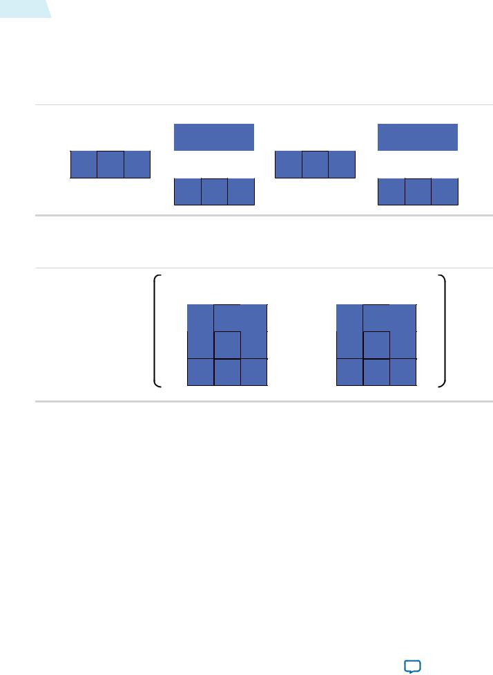
Figure 12-2: Pixel Assembly for the Motion-Adaptive Algorithm
Previous Frame |
Current Frame |
Motion = MAD
,
3.The minimum absolute difference value is normalized into the same range as the input pixel data. If you select the Motion bleed algorithm, the function compares the motion value with a recorded motion value for the same location in the previous frame. If it is greater, the function keeps the new value; if the new value is less than the stored value, the function uses the motion value that is the mean of the two values. This action reduces unpleasant flickering artefacts but increases the memory usage and memory bandwidth requirements.
4.Two pixels are selected for interpolation by examining the 3×3 group of pixels from the more recent two fields for edges. If the function detects a diagonal edge, the function selects two pixels from the current field that lie on the diagonal, otherwise the function chooses the pixels directly above and below the output pixel.
Note: The 4:2:2 compatibility mode prevents incorrect interpolation of the chroma samples along the diagonal edges.
5.The function uses a weighted mean of the interpolation pixels to calculate the output pixel and the equivalent to the output pixel in the previous field with the following equation:
Altera Corporation |
Deinterlacing IP Cores |
|
|
Send Feedback

UG-VIPSUITE |
Sobel-Based HQ Mode |
12-5 |
|
2015.01.23 |
|
||
|
|
|
|
|
|
|
|
The motion-adaptive algorithm requires the buffering of two frames of data before it can produce any output. The Deinterlacer always consumes the three first fields it receives at start up and after a change of resolution without producing any output.
Note: The weave and motion-adaptive algorithms cannot handle fields of different sizes (for example, 244 lines for F0 and 243 lines for F1). Both implementations discard input fields and do not produce an output frame until they receive a sufficient number of consecutive fields with matching sizes.
Sobel-Based HQ Mode
The Broadcast Deinterlacer and Deinterlacer II IP cores use a new Sobel edge detection-based algorithm, which improves image quality.
The improvement is most noticeable when upscaling Secure Digital (SD) video to High Definition (HD) video. Other Deinterlacer II improvements include the reduction of motion shadow and high quality output from the first frame.
Figure 12-3: Deinterlacer II High Quality Mode Zoneplate version 12.0 and 12.1
The figure shows the difference between the Deinterlacer II HQ mode zoneplate version 12.0 and the new version 12.1
Version 12.0 |
Version 12.1 |
Deinterlacing IP Cores |
Altera Corporation |
|
|
Send Feedback