- •Contents
- •1. Video and Image Processing Suite Overview
- •Release Information
- •Device Family Support
- •Latency
- •In-System Performance and Resource Guidance
- •Stall Behavior and Error Recovery
- •2. Interfaces
- •Video Formats
- •Avalon-ST Video Protocol
- •Video Data Packets
- •Static Parameters of Video Data Packets
- •Control Data Packets
- •Ancillary Data Packets
- •User-Defined and Altera-Reserved Packets
- •Packet Propagation
- •Transmission of Avalon-ST Video Over Avalon-ST Interfaces
- •Packet Transfer Examples
- •Avalon-MM Slave Interfaces
- •Specification of the Type of Avalon-MM Slave Interfaces
- •Avalon-MM Master Interfaces
- •Specification of the Type of Avalon-MM Master Interfaces
- •Buffering of Non-Image Data Packets in Memory
- •3. Getting Started
- •IP Catalog and Parameter Editor
- •Specifying IP Core Parameters and Options
- •Installing and Licensing IP Cores
- •OpenCore Plus IP Evaluation
- •4. Clocked Video Interface IP Cores
- •Control Port
- •Clocked Video Input Format Detection
- •Interrupts
- •Clocked Video Output Video Modes
- •Interrupts
- •Generator Lock
- •Underflow and Overflow
- •Timing Constraints
- •Handling Ancillary Packets
- •Modules for Clocked Video Input II IP Core
- •Clocked Video Interface Parameter Settings
- •Clocked Video Interface Signals
- •Clocked Video Interface Control Registers
- •5. 2D FIR Filter IP Core
- •Calculation Precision
- •Coefficient Precision
- •Result to Output Data Type Conversion
- •2D FIR IP Core Parameter Settings
- •2D FIR Filter Signals
- •2D FIR Filter Control Registers
- •6. Video Mixing IP Cores
- •Alpha Blending
- •Video Mixing Parameter Settings
- •Video Mixing Signals
- •Video Mixing Control Registers
- •7. Chroma Resampler IP Core
- •Horizontal Resampling (4:2:2)
- •Vertical Resampling (4:2:0)
- •Chroma Resampler Parameter Settings
- •Chroma Resampler Signals
- •8. Video Clipping IP Cores
- •Video Clipping Parameter Settings
- •Video Clipping Signals
- •Video Clipping Control Registers
- •9. Color Plane Sequencer IP Core
- •Combining Color Patterns
- •Rearranging Color Patterns
- •Splitting and Duplicating
- •Subsampled Data
- •Color Plane Sequencer Parameter Settings
- •Color Plane Sequencer Signals
- •10. Color Space Conversion IP Cores
- •Input and Output Data Types
- •Color Space Conversion
- •Result of Output Data Type Conversion
- •Color Space Conversion Parameter Settings
- •Color Space Conversion Signals
- •Color Space Conversion Control Registers
- •11. Control Synchronizer IP Core
- •Using the Control Synchronizer IP Core
- •Control Synchronizer Parameter Settings
- •Control Synchronizer Signals
- •Control Synchronizer Control Registers
- •12. Deinterlacing IP Cores
- •Deinterlacing Methods
- •Bob with Scanline Duplication
- •Bob with Scanline Interpolation
- •Weave
- •Motion-Adaptive
- •Sobel-Based HQ Mode
- •Pass-Through Mode for Progressive Frames
- •Frame Buffering
- •Frame Rate Conversion
- •Bandwidth Requirement Calculations for 10-bit YCbCr Video
- •Behavior When Unexpected Fields are Received
- •Handling of Avalon-ST Video Control Packets
- •Deinterlacing Parameter Settings
- •Deinterlacing Signals
- •Deinterlacing Control Registers
- •Design Guidelines for Broadcast Deinterlacer IP Core
- •13. Frame Reader IP Core
- •Single-Cycle Color Patterns
- •Frame Reader Output Pattern and Memory Organization
- •Frame Reader Parameter Settings
- •Frame Reader Signals
- •Frame Reader Control Registers
- •14. Frame Buffer IP Cores
- •Double Buffering
- •Triple Buffering
- •Locked Frame Rate Conversion
- •Handling of Avalon-ST Video Control Packets
- •Color Format
- •Frame Buffer Parameter Settings
- •Frame Buffer Signals
- •Frame Buffer Control Registers
- •15. Gamma Corrector IP Core
- •Gamma Corrector Parameter Settings
- •Gamma Corrector Signals
- •Gamma Corrector Control Registers
- •16. Interlacer IP Core
- •Interlacer Parameter Settings
- •Interlacer Signals
- •Interlacer Control Registers
- •17. Scaler II IP Core
- •Nearest Neighbor Algorithm
- •Bilinear Algorithm
- •Bilinear Algorithmic Description
- •Polyphase and Bicubic Algorithm
- •Double-Buffering
- •Polyphase Algorithmic Description
- •Choosing and Loading Coefficients
- •Edge-Adaptive Scaling Algorithm
- •Scaler II Parameter Settings
- •Scaler II Signals
- •Scaler II Control Registers
- •18. Video Switching IP Cores
- •Mixer Layer Switching
- •Video Switching Parameter Settings
- •Video Switching Signals
- •Video Switching Control Registers
- •19. Test Pattern Generator IP Cores
- •Test Pattern
- •Generation of Avalon-ST Video Control Packets and Run-Time Control
- •Test Pattern Generator Parameter Settings
- •Test Pattern Generator Signals
- •Test Pattern Generator Control Registers
- •20. Trace System IP Core
- •Trace System Parameter Settings
- •Trace System Signals
- •Operating the Trace System from System Console
- •Loading the Project and Connecting to the Hardware
- •Trace Within System Console
- •TCL Shell Commands
- •21. Avalon-ST Video Monitor IP Core
- •Packet Visualization
- •Monitor Settings
- •Avalon-ST Video Monitor Parameter Settings
- •Avalon-ST Video Monitor Signals
- •Avalon-ST Video Monitor Control Registers
- •Avalon-ST Video Class Library
- •Running the Tests
- •Video File Reader Test
- •Example Test Environment
- •Video Field Life Cycle
- •Constrained Random Test
- •Complete Class Reference
- •c_av_st_video_control
- •c_av_st_video_data
- •c_av_st_video_file_io
- •c_av_st_video_item
- •c_av_st_video_source_sink_base
- •c_av_st_video_sink_bfm_’SINK
- •c_av_st_video_source_bfm_’SOURCE
- •c_av_st_video_user_packet
- •c_pixel
- •Raw Video Data Format
- •Cadence Detection and Reverse Pulldown in the Deinterlacer II IP Core
- •Document Revision History
- •How to Contact Altera
Trace System IP Core 20
2015.01.23
UG-VIPSUITE |
Subscribe |
Send Feedback |
The Trace System IP core is a debugging and monitoring component.
The trace system collects data from various monitors, such as the Avalon-ST monitor, and passes it to System Console software on the attached debugging host. System Console software captures and visualizes the behavior of the attached system. You can transfer data to the host over one of the following connections:
•Direct USB connection with a higher bandwidth; for example On-Board USB-Blaster™ II
•If you select the USB connection to the host, the trace system exposes the usb_if interface.
•Export this interface from the Qsys system and connect to the pins on the device that connects to the On-Board USB-Blaster II.
Note: To manually connect the usb_if conduit, use the USB Debug Link component, located in
Verification > Debug & Performance.
•JTAG connection
•If you select the JTAG connection to the host, then the Quartus II software automatically makes the pin connection during synthesis.
The Trace System IP core transports messages describing the captured events from the trace monitor components, such as the Frame Reader, to a host computer running the System Console software.
Figure 20-1: Trace System Functional Block Diagram
Conduit for connection to pins (USB only)
|
Altera Trace System |
Avalon-ST Source |
|
|
(capture) |
|
|
Monitor #1 |
Link to Host |
Buffering |
Avalon-MM Slave |
(control) |
||
|
|
Monitor #2 |
When you instantiate the Trace System IP core, turn on the option to select the number of monitors required. The trace system exposes a set of interfaces: capturen and controln. You must connect each pair of the interfaces to the appropriate trace monitor component.
© 2015 Altera Corporation. All rights reserved. ALTERA, ARRIA, CYCLONE, ENPIRION, MAX, MEGACORE, NIOS, QUARTUS and STRATIX words and logos are trademarks of Altera Corporation and registered in the U.S. Patent and Trademark Office and in other countries. All other words and logos identified as trademarks or service marks are the property of their respective holders as described at www.altera.com/common/legal.html. Altera warrants performance of its semiconductor products to current specifications in accordance with Altera's standard warranty, but reserves the right to make changes to any products and services at any time without notice. Altera assumes no responsibility or liability arising out of the application or use of any information, product, or service described herein except as expressly agreed to in writing by Altera. Altera customers are advised to obtain the latest version of device specifications before relying on any published information and before placing orders for products or services.
ISO 9001:2008 Registered
www.altera.com
101 Innovation Drive, San Jose, CA 95134
20-2 |
Trace System Parameter Settings |
UG-VIPSUITE |
|
2015.01.23 |
|||
|
|
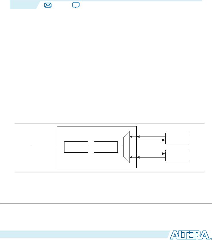
The IP core provides access to the control interfaces on the monitors. You can use these control ports to change the capture settings on the monitors; for example, to control the type of information captured by the monitors or to control the maximum data rate sent by the monitor.
Note: Each type of monitor is different. Refer to the relevant documentation of the monitors for more information.
Each trace monitor sends information about interesting events through its capture interface. The trace system multiplexes these data streams together and, if the trace system is running, stores them into a FIFO buffer. The contents of this buffer are streamed to the host using as much as the available trace bandwidth.
The amount of buffering required depends on the amount of jitter inserted by the link, in most cases, the default value of 32Kbytes is sufficient.
Note: The System Console uses the sopcinfo file written by Qsys to discover the connections between the Trace System IP core and the monitors. If you instantiate and manually connect the Trace System IP core and the monitors using HDL, the System Console will not detect them.
Trace System Parameter Settings
Table 20-1: Trace System Parameter Settings
Parameter |
|
|
Value |
|
Description |
|
|
|
|
|
|
Export interfaces for connection |
|
Yes or No |
|
If you select USB as the connection to host, |
|
to manual debug fabric |
|
|
|
|
selecting Yes shows the usb_if conduit— |
|
|
|
|
|
enables you to manually connect this |
|
|
|
|
|
interface. |
|
|
|
|
|
|
Connection to host |
|
• |
JTAG |
|
Select the type of connection to the host |
|
|
• |
USB |
|
running the System Console. |
|
|
|
|
||
|
|
|
|
|
|
Bit width of capture interface(s) |
|
8–128, Default = 32 |
|
Select the data bus width of the Avalon-ST |
|
|
|
|
|
|
interface sending the captured information. |
|
|
|
|
|
|
Number of inputs |
|
2–16, Default = 2 |
|
Select the number of trace monitors which |
|
|
|
|
|
|
will be connected to this trace system. |
Buffer size |
|
8192–65536, Default = |
|
Select the size of the jitter buffer in bytes. |
|
|
|
32768 |
|
|
|
|
|
|
|
|
|
Insert pipeline stages |
|
On or Off |
|
Turn on to insert the pipeline stages within |
|
|
|
|
|
|
the trace system. Turning on this parameter |
|
|
|
|
|
gives a higher fmax but uses more logic. |
Altera Corporation |
Trace System IP Core |
|
|
Send Feedback
UG-VIPSUITE |
Trace System Signals |
20-3 |
|
2015.01.23 |
|||
|
|
Trace System Signals
Table 20-2: Trace System Signals
|
Signal |
|
Direction |
|
Description |
|
|
|
|
|
|
|
|
|
|
|
clk_clk |
|
Input |
|
All signals on the trace system are synchronous to this |
||
|
|
|
|
|
clock. |
||
|
|
|
|
|
Do not insert clock crossing between the monitor and |
||
|
|
|
|
|
the trace system components. You must drive the |
||
|
|
|
|
|
trace monitors’ clocks from the same source which |
||
|
|
|
|
|
drives this signal. |
||
|
|
|
|
|
|
|
|
|
reset_reset |
|
Output |
|
This signal is asserted when the IP core is being reset |
|
|
|
|
|
|
|
by the debugging host. Connect this signal to the reset |
|
|
|
|
|
|
|
inputs on the trace monitors. |
|
|
|
|
|
|
|
Do not reset parts of the system being monitored with |
|
|
|
|
|
|
|
this signal because this will interfere with function |
|
|
|
|
|
|
|
ality of the system. |
|
|
|
|
|
|
|
|
|
|
|
usb_if_clk |
|
Input |
|
Clock provided by On-Board USB-Blaster II. |
||
|
|
|
|
|
All usb_if signals are synchronous to this clock; the |
||
|
|
|
|
|
trace system provides clock crossing internally. |
||
|
|
|
|
|
|
|
|
|
usb_if_reset_n |
|
Input |
|
Reset driven by On-Board USB-Blaster II. |
|
|
|
|
|
|
|
|
|
|
|
usb_if_full |
|
Output |
|
Host to the target full signal. |
||
|
|
|
|
|
|
|
|
|
usb_if_empty |
|
Output |
|
Target to the host empty signal. |
|
|
|
|
|
|
|
|
|
|
|
usb_if_wr_n |
|
Input |
|
Write enable to the host to target FIFO. |
||
|
|
|
|
|
|
|
|
|
usb_if_rd_n |
|
Input |
|
Read enable to the target to host FIFO. |
|
|
|
|
|
|
|
|
|
|
|
usb_if_oe_n |
|
Input |
|
Output enable for data signals. |
||
|
|
|
|
|
|
|
|
|
usb_if_data |
|
Bidirectional |
|
Shared data bus. |
|
|
|
|
|
|
|
|
|
|
|
usb_if_scl |
|
Input |
|
Management interface clock. |
||
|
|
|
|
|
|
|
|
|
usb_if_sda |
|
Input |
|
Management interface data. |
|
|
|
|
|
|
|
|
|
|
|
capturen_data |
|
Input |
|
capturen port Avalon-ST data bus. This bus enables |
||
|
|
|
|
|
the transfer of data out of the IP core. |
||
|
|
|
|
|
|
|
|
|
capturen_endofpacket |
|
Input |
|
capturen port Avalon-ST endofpacket signal. This |
|
|
|
|
|
|
|
signal marks the end of an Avalon-ST packet. |
|
|
|
capturen_empty |
|
Input |
|
capturen port Avalon-ST empty signal. |
|
|
|
|
|
|
|
|
|
|
|
capturen_ready |
|
Output |
|
capturen port Avalon-ST ready signal. The |
|
|
|
|
|
|
|
downstream device asserts this signal when it is able |
|
|
|
|
|
|
|
to receive data. |
|
|
|
|
|
|
|
|
|
|
Trace System IP Core |
|
|
|
|
Altera Corporation |
||
|
Send Feedback |
|
|
|
|
|
|