

UG-VIPSUITE |
|
|
Video Data Packets |
2-11 |
|
|||
2015.01.23 |
|
|
|
|
||||
|
|
|
|
|
|
|||
|
|
|
|
|
|
|
|
|
|
|
Type Identifier |
|
Description |
|
|
||
|
|
|
|
|
|
|
|
|
13 |
|
|
Ancillary data packet |
|
|
|||
|
|
|
|
|
|
|
|
|
14 |
|
|
Reserved for future Altera use |
|
|
|||
|
|
|
|
|
|
|
|
|
15 |
|
|
Control data packet |
|
|
|||
|
|
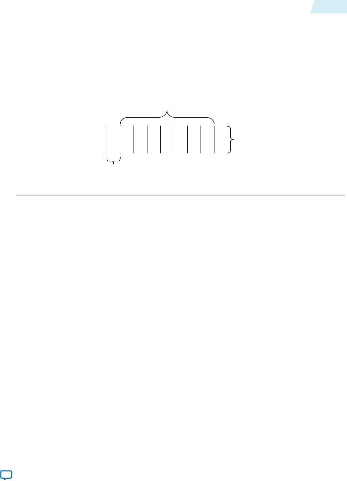
Figure 2-7: Packet Structure |
|
|
|
|
|
|
|
|
|
|
|
|
|
|
|
|
|
|
|
|
Data of the packet |
|
|
|
|
|
|
|
|
(Split into symbols) |
|
|
|
|
|
|
|
|
|
|
|
|
|
|
|
X |
|
|
Symbols can be |
|
|
|
|
|
|
|
|
transmitted in parallel |
|
|
|
|
|
|
|
|
|
|
|
|
|
|
|
|
|
(2 in this example) |
|
|
Start |
|
End |
Packet type identifier |
|
|
(4 bits in least significant symbol, |
|
|
X’s for unused symbols) |
|
|
The Avalon-ST Video protocol is designed to be most efficient for transferring video data, therefore the symbol bit width and the number of symbols transferred in parallel (that is, in one clock cycle) are defined by the parameters of the video data packet types.
Video Data Packets
Video data packets transmit video data between the IP cores.
A video data packet contains the color plane values of the pixels for an entire progressive frame or an entire interlaced field.
The IP core sends the video data per pixel in a raster scan order. The pixel order is as follows:
1.From the top left of the image right wards along the horizontal line.
2.At the end of the current line, jump to the left most pixel of the next horizontal line down.
3.Go rightwards along the horizontal line.
4.Repeat steps 2 and 3 until the bottom right pixel is reached and the frame has been sent.
Static Parameters of Video Data Packets
Two static parameters specify the Avalon-ST interface that video systems use—bits per pixel per color plane and color pattern.
Bits Per Pixel Per Color Plane
The maximum number of bits that represent each color plane value within each pixel. For example, R’G’B’ data of eight bits per sample (24 bits per pixel) would use eight bits per pixel per color plane.
Note: This parameter also defines the bit width of symbols for all packet types on a particular Avalon-ST interface. An Avalon-ST interface must be at least four bits wide to fully support the Avalon-ST Video protocol.
Interfaces |
Altera Corporation |
|
|
Send Feedback

2-12 |
Static Parameters of Video Data Packets |
UG-VIPSUITE |
|
2015.01.23 |
|||
|
|
Color Pattern
The organization of the color plane samples within a video data packet is referred to as the color pattern.
This parameter also defines the bit width of symbols for all packet types on a particular Avalon-ST interface. An Avalon-ST interface must be at least four bits wide to fully support the Avalon-ST Video protocol.
A color pattern is represented as a matrix which defines a repeating pattern of color plane samples that make up a pixel (or multiple pixels). The height of the matrix indicates the number of color plane samples transmitted in parallel, the width determines how many cycles of data are transmitted before the pattern repeats.
Each color plane sample in the color pattern maps to an Avalon-ST symbol. The mapping is such that color plane samples on the left of the color pattern matrix are the symbols transmitted first. Color plane samples on the top are assigned to the symbols occupying the most significant bits of the Avalon-ST data signal.
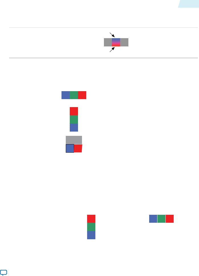
Figure 2-8: Symbol Transmission Order
Symbol transmitted first |
|
||||||||||
|
|
|
|
|
|
|
|
Symbol in most significant bits |
|
|
R |
|
|
|
|
|
|
|
|
|
|||
|
|
|
|
|
|
|
|
|
|
|
|
|
B |
|
G |
R |
|
|
|
G |
|||
|
|
|
|
|
|
|
|
Symbol in least significant bits |
|
|
|
|
|
|
|
|
|
|
|
|
|
B |
|
|
|
|
|
|
|
|
|
|
|||
|
|
|
Symbol transmitted last |
|
|||||||
|
|
|
|
||||||||
Note: The number of color plane samples transmitted in parallel (that is, in one clock cycle) defines the number of symbols transmitted in parallel for all packet types on a particular Avalon-ST interface.
A color pattern can represent more than one pixel. This is the case when consecutive pixels contain samples from different color planes—There must always be at least one common color plane between all pixels in the same color pattern. Color patterns representing more than one pixel are identifiable by a repeated color plane name. The number of times a color plane name is repeated is the number of pixels represented.
Figure 2-9: Horizontally Subsampled Y'CbCr
The figure below shows two pixels of horizontally subsampled Y' CbCr (4:2:2) where Cb and Cr alternate between consecutive pixels.
Y Y
Cb Cr
In the common case, each element of the matrix contains the name of a color plane from which a sample must be taken. The exception is for vertically sub sampled color planes. These are indicated by writing the names of two color planes in a single element, one above the other.
Altera Corporation |
Interfaces |
|
|
Send Feedback
UG-VIPSUITE |
Static Parameters of Video Data Packets |
2-13 |
|
2015.01.23 |
|||
|
|
Figure 2-10: Vertically Subsampled Y'CbCr
The figure below samples from the upper color plane transmitted on even rows and samples from the lower plane transmitted on odd rows.
Plane for even rows
Y |
Cb |
Y |
|
Cr |
|||
|
|
Plane for odd rows
Table 2-5: Examples of Static Avalon-ST Video Data Packet Parameters
The table below lists the static parameters and gives some examples of how you can use them.
Parameter |
|
|
|
|
|
|
|
|
|
|
|
|
Description |
|
|
|
|
|
|
|
|
|
|
|
|
||
|
|
|
|
|
|
|
|
|
|
|
|
||
Bits per Color Sample |
|
|
Color Pattern |
|
|
||||||||
|
|
|
|
|
|
|
|
|
|
|
|
|
|
8 |
|
|
|
|
|
|
|
|
|
|
|
|
Three color planes, B’, G’, and R’ are transmitted in |
|
|
B |
|
G |
|
R |
|
|
|||||
|
|
|
|
|
|
|
alternating sequence and each B’, G’, or R’ sample is |
||||||
|
|
|
|
|
|
|
|
|
|
|
|
|
|
|
|
|
|
|
|
|
|
|
|
|
|
|
represented using 8 bits of data. |
|
|
|
|
|
|
|
|
|
|
|
|
|
|
10 |
|
|
|
|
|
|
|
|
|
|
|
|
Three color planes are transmitted in parallel, leading to |
|
|
|
|
|
R |
|
|
|
|
|
|||
|
|
|
|
|
|
|
|
|
|
|
higher throughput than when transmitted in sequence, |
||
|
|
|
|
|
|
G |
|
|
|
|
|
usually at higher cost. Each R’, G’, or B’ sample is |
|
|
|
|
|
|
|
|
|
|
|
|
represented using 10 bits of data, so that, in total, 30 bits |
||
|
|
|
|
|
|
B |
|
|
|
|
|
of data are transmitted in parallel. |
|
|
|
|
|
|
|
|
|
|
|
|
|
|
|
10 |
|
|
|
|
|
|
|
|
|
|
|
|
4:2:2 video in the Y’CbCr color space, where there are |
|
|
|
|
Y |
|
Y |
|
|
|
||||
|
|
|
|
|
|
|
|
twice as many Y’ samples as Cb or Cr samples. One Y’ |
|||||
|
|
|
|
|
|
|
|
|
|
|
|
|
|
|
|
|
|
|
Cb |
|
Cr |
|
|
sample and one of either a Cb or a Cr sample is |
|||
|
|
|
|
|
|
|
|
|
|
|
|
|
transmitted in parallel. Each sample is represented using |
|
|
|
|
|
|
|
|
|
|
|
|
|
10 bits of data. |
|
|
|
|
|
|
|
|
|
|
|
|
|
|
The Avalon-ST Video protocol does not force the use of specific color patterns, however a few IP cores of the Video and Image Processing Suite only process video data packets correctly if they use a certain set of color patterns.
Table 2-6: Recommended Color Patterns
The table below lists the recommended color patterns for common combinations of color spaces and color planes in parallel and sequence.
Parameter |
|
|
|
|
Recommended Color Patterns |
||||||
|
|
|
|
|
|
|
|
|
|
|
|
|
|
|
|
|
|
|
|
|
|
|
|
Bits per Color Sample |
|
Parallel |
|
|
|
Sequence |
|||||
|
|
|
|
|
|
|
|
|
|
|
|
R’G’B |
|
|
|
|
|
|
|
|
|
|
|
|
|
R |
|
|
|
|
B |
G |
R |
|
|
|
|
|
|
|
|
|
|
||||
|
|
|
|
|
|
|
|
|
|
|
|
|
|
|
G |
|
|
|
|
|
|
|
|
|
|
|
|
|
|
|
|
|
|
|
|
|
|
|
B |
|
|
|
|
|
|
|
|
|
|
|
|
|
|
|
|
|
|
|
|
|
|
|
|
|
|
|
|
|
|
|
|
Interfaces |
Altera Corporation |
|
|
Send Feedback
2-14 |
Static Parameters of Video Data Packets |
|
|
|
|
|
|
|
|
|
|
|
|
|
|
|
|
|
|
UG-VIPSUITE |
||||
|
|
|
|
|
|
|
|
|
|
|
|
|
|
|
2015.01.23 |
|||||||||
|
|
|
|
|
|
|
|
|
|
|
|
|
|
|
|
|
|
|
|
|||||
|
|
|
|
|
|
|
|
|
|
|
|
|
|
|
|
|
|
|
|
|
|
|
|
|
|
|
Parameter |
|
|
|
|
|
|
|
Recommended Color Patterns |
|
|
|
|
|
|
|
|
|
|||||
|
|
|
|
|
|
|
|
|
|
|
|
|
|
|
|
|
|
|
|
|
|
|||
|
|
Bits per Color Sample |
|
|
Parallel |
|
|
|
|
Sequence |
|
|||||||||||||
|
|
|
|
|
|
|
|
|
|
|
|
|
|
|
|
|
|
|
|
|
|
|
|
|
|
|
Y’CbCr |
|
|
|
|
|
|
|
|
|
|
|
|
|
|
|
|
|
|
|
|
|
|
|
|
|
|
Y |
|
|
|
|
|
Cb |
|
Cr |
|
Y |
|
|
|
|||||||
|
|
|
|
|
|
|
|
|
|
|
|
|
|
|
|
|
||||||||
|
|
|
|
|
|
|
Cr |
|
|
|
|
|
|
|
|
|
|
|
|
|
|
|
|
|
|
|
|
|
|
|
|
|
|
|
|
|
|
|
|
|
|
|
|
|
|
|
|
|
|
|
|
|
|
|
|
|
Cb |
|
|
|
|
|
|
|
|
|
|
|
|
|
|
|
|
|
|
|
|
|
|
|
|
|
|
|
|
|
|
|
|
|
|
|
|
|
|
|
|
|
|
|
|
|
|
|
|
|
|
|
|
|
|
|
|
|
|
|
|
|
|
|
|
|
|
|
|
|
4:2:2 Y’CbCr |
|
|
|
|
|
|
|
|
|
|
|
|
|
|
|
|
|
|
|
|
|
|
|
|
Y |
|
Y |
|
|
|
Cb |
|
Y |
Cr |
|
Y |
|
|
|||||||||
|
|
|
|
|
|
|
|
|
|
|
|
|||||||||||||
|
|
|
|
|
|
|
|
|
|
|
|
|
|
|
|
|
|
|
|
|
|
|
||
|
|
|
|
|
Cb |
|
Cr |
|
|
|
|
|
|
|
|
|
|
|
|
|
|
|
||
|
|
|
|
|
|
|
|
|
|
|
|
|
|
|
|
|
|
|
|
|
|
|
|
|
|
|
|
|
|
|
|
|
|
|
|
|
|
|
|
|
|
|
|
|
|
|
|
|
|
Following these recommendations, ensures compatibility minimizing the need for color pattern rearranging. These color patterns are designed to be compatible with common clocked video standards where possible.
Note: If you must rearrange color patterns, use the Color Plane Sequencer IP core.
4:2:2 Mode Support
Some of the IP cores in the Video and Image Processing Suite do not support 4:2:2 mode. You can parameterize the IP cores to 2 symbols in parallel or sequence to make them appear like 4:2:2.
The following IP cores do not support 4:2:2 mode:
•2D FIR Filter
•Color Space Converter
Some IP cores use 2-pixel alignment of 4:2:2. These IP cores send pixels in “pairs” to get a complete “Y, Cb and Cr”. The following IP cores use 2-pixel alignment:
•Alpha Blending Mixer
•Clipper
•Clipper II
•Gamma Corrector
Specifying Color Pattern Options
You can specify parameters in the parameter editor that allow you to describe a color pattern that has its color planes entirely in sequence (one per cycle) or entirely in parallel (all in one cycle). You can select the number of color planes per pixel, and whether the planes of the color pattern transmit in sequence or in parallel.
Some of the IP cores' user interfaces provide controls allowing you to describe a color pattern that has color plane samples in parallel with each other and in sequence such that it extends over multiple clock cycles. You can select the number of color planes of the color pattern in parallel (number of rows of the color pattern) and the number of color planes in sequence (number of columns of the color pattern).
Altera Corporation |
Interfaces |
|
|
Send Feedback