

FLIGHT INSTRUMENTS
2.1 FLIGHT INSTRUMENTS
AIRSPEED INDICATOR
 NOTE: Refer to the Pilot’s Operating Handbook (POH) for speed criteria and Vspeed values.
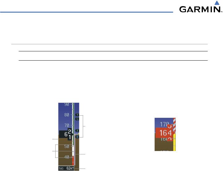
The Airspeed Indicator displays airspeed on a rolling number gauge using a moving tape. The true airspeed is displayed in knots below the Airspeed Indicator. The numeric labels and major tick marks on the moving tape are marked at intervals of 10 knots, while minor tick marks on the moving tape are indicated at intervals of 5 knots. Speed indication starts at 20 knots, with 60 knots of airspeed viewable at any time. The actual airspeed is displayed inside the black pointer. The pointer remains black until reaching never-exceed speed (VNE), at which point it turns red.
Vspeed References
Actual Airspeed
Speed Ranges
Airspeed Trend Vector
Figure 2-4 Red Pointer Showing
Overspeed (Model 172R)
True Airspeed
Figure 2-3 Airspeed Indicator (Model 182T)
A color-coded (white, green, yellow, and red) speed range strip is located on the moving tape. The colors denote flaps operating range, normal operating range, caution range, and never-exceed speed (VNE). A red range is also present for low speed awareness.
The Airspeed Trend Vector is a vertical, magenta line, extending up or down on the airspeed scale, shown to the right of the color-coded speed range strip. The end of the trend vector corresponds to the predicted airspeed in 6 seconds if the current rate of acceleration is maintained. If the trend vector crosses VNE, the text of the actual airspeed readout changes to yellow. The trend vector is absent if the speed remains constant or if any data needed to calculate airspeed is not available due to a system failure.
2-4 |
Garmin G1000 Pilot’s Guide for Cessna Nav III |
190-00498-03 Rev.A |
FLIGHT INSTRUMENTS
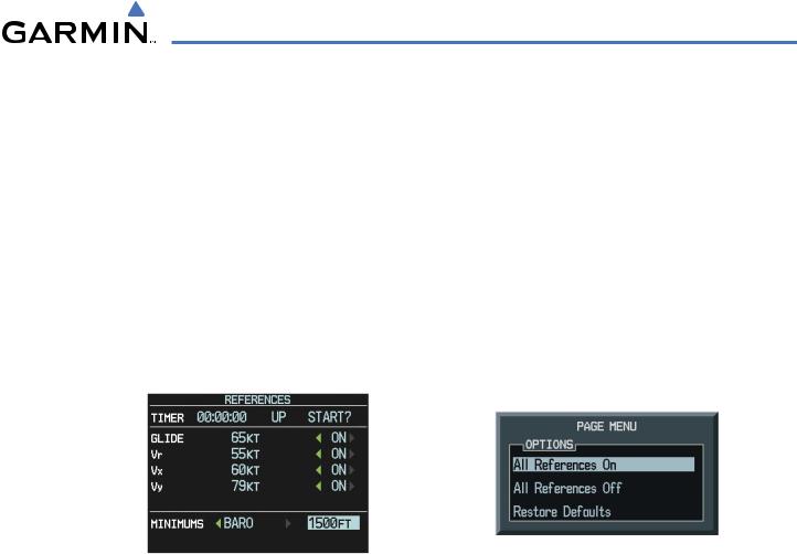
Vspeeds (Glide, VR, VX, and VY) can be changed and their flags turned on/off from the Timer/References Window. When active (on), the Vspeeds are displayed at their respective locations to the right of the airspeed scale. By default, all Vspeed values are reset and all flags turned off when power is cycled.
Changing Vspeeds and turning Vspeed flags ON/OFF:
1)Press the TMR/REF Softkey.
2)Turn the large FMS Knob to highlight the desired Vspeed.
3)Use the small FMS Knob to change the Vspeed in 1-kt increments (when a speed has been changed from a default value, an asterisk appears next to the speed).
4)Press the ENT Key or turn the large FMS Knob to highlight the ON/OFF field
5)Turn the small FMS Knob clockwise to ON or counterclockwise to OFF.
6)To remove the window, press the CLR Key or the TMR/REF Softkey.
Figure 2-6 Timer/References Menu
Figure 2-5 Timer/References Window (Model 172R)
Turning all Vspeed flags on/off:
1)Press the TMR/REF Softkey.
2)Press the MENU Key.
3)To view all Vspeed flags, press the ENT Key with ‘All References On’ highlighted.
4)To remove all Vspeed flags, turn the FMS Knob to highlight ‘All References Off’ and press the ENT Key.
Restoring all Vspeed defaults:
1)Press the TMR/REF Softkey.
2)Press the MENU Key.
3)Turn the FMS Knob to highlight ‘Restore Defaults’ and press the ENT Key.
190-00498-03 Rev.A |
Garmin G1000 Pilot’s Guide for Cessna Nav III |
2-5 |
FLIGHT INSTRUMENTS
ATTITUDE INDICATOR
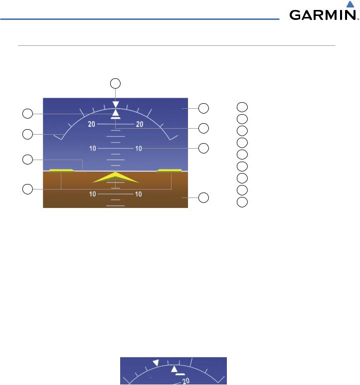
Attitude information is displayed over a virtual blue sky and brown ground with a white horizon line. The Attitude Indicator displays the pitch, roll, and slip/skid information.
9
8 |
1 |
Roll Pointer |
|
1 |
2 |
Roll Scale |
|
|
|||
7 |
3 |
Horizon Line |
|
2 |
|||
|
|
||
6 |
4 |
Aircraft Symbol |
|
|
|
5 Land Representation
3
|
|
6 |
Pitch Scale |
|
|
7 |
Slip/Skid Indicator |
4 |
5 |
8 |
Sky Representation |
|
9 |
Roll Scale Zero |
|
|
|
Figure 2-7 Attitude Indicator
The horizon line is part of the pitch scale. Above and below the horizon line, major pitch marks and numeric labels are shown for every 10˚, up to 80˚. Minor pitch marks are shown for intervening 5˚ increments, up to 25˚ below and 45˚ above the horizon line. Between 20˚ below to 20˚ above the horizon line, minor pitch marks occur every 2.5˚.
The inverted white triangle indicates zero on the roll scale. Major tick marks at 30˚ and 60˚ and minor tick marks at 10˚, 20˚, and 45˚ are shown to the left and right of the zero. Angle of bank is indicated by the position of the pointer on the roll scale.
The Slip/Skid Indicator is the bar beneath the roll pointer. The indicator moves with the roll pointer and moves laterally away from the pointer to indicate lateral acceleration. Slip/skid is indicated by the location of the bar relative to the pointer. One bar displacement is equal to one ball displacement on a traditional Slip/Skid Indicator (Figure 2-8).
Figure 2-8 Slip/Skid Indication
2-6 |
Garmin G1000 Pilot’s Guide for Cessna Nav III |
190-00498-03 Rev.A |
FLIGHT INSTRUMENTS
ALTIMETER
The Altimeter displays 600 feet of barometric altitude values at a time on a rolling number gauge using a moving tape. Numeric labels and major tick marks are shown at intervals of 100 feet. Minor tick marks are at intervals of 20 feet. The current altitude is displayed in the black pointer.
The Selected Altitude is displayed above the Altimeter in the box indicated by a selection bug symbol. A bug corresponding to this altitude is shown on the tape; if the Selected Altitude exceeds the range shown on the tape, the bug appears at the corresponding edge of the tape. See the AFCS Section for more information about how the G1000 uses Selected Altitude.
Setting the Selected Altitude:
Turn the ALT Knob to set the SelectedAltitude in 100-ft increments (increments reduce to 10 feet for approach) up to the aircraft’s service ceiling.
If set, the Minimum Descent Altitude/Decision Height (MDA/DH) value is also available for the Selected Altitude.
Selected
Selected Altitude
Altitude
Bug
Altitude |
|
|
Trend |
Current |
|
Vector |
||
Altitude |
||
|
||
Minimum Descent |
|
|
Altitude/Decision |
|
|
Height Bug |
|
|
|
Barometric |
|
|
Setting |
|
Figure 2-9 Altimeter |
Figure 2-10 Altimeter (Metric Units) |
Selected and current altitudes can also be displayed in meters (readouts displayed above the normal readouts in feet; Figure 2-10). Note that the altitude tape does not change scale.
Displaying altitude in meters:
1)Press the PFD Softkey to display the second-level softkeys.
2)Press the ALT UNIT Softkey.
3)Press the METERS Softkey to turn on metric altitude readouts (see Figure 2-10).
4)Press the BACK Softkey twice to return to the top-level softkeys.
190-00498-03 Rev.A |
Garmin G1000 Pilot’s Guide for Cessna Nav III |
2-7 |