

FLIGHT INSTRUMENTS
2.3 PFD ANNUNCIATIONS AND ALERTING FUNCTIONS
The following annunciations and alerting functions are displayed on the PFD. Refer to Appendix A for more information on alerts and annunciations.
G1000 SYSTEM ALERTING
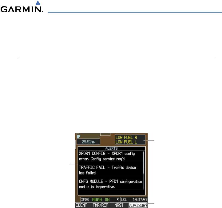
Messages appear in the Alerts Window (in the lower right corner of the PFD; Figure 2-33) when a warning, caution, advisory alert, or G1000 message advisory occurs. System alert messages are provided for awareness of G1000 system problems or status and may not require pilot action. The Alerts Window allows system alerts to be displayed simultaneously. The FMS Knob can be used to scroll through the alert messages. The Alerts Window is enabled/disabled by pressing the ALERTS Softkey. If the window is already open when a new message is generated, pressing the ALERTS Softkey to acknowledge the message causes it to turn gray.
The Annunciation Window appears to the right of the Vertical Speed Indicator and displays abbreviated annunciation text for aircraft alerts. Text color is based on alert level: warnings appear in red, cautions in yellow, advisory alerts in white and safe advisories appear in green. New alerts, regardless of priority, are displayed at the top of the Annunciation Window, separated by a white line from acknowledged alerts. Once acknowledged, they are sequenced based on priority.
Annunciation
Window
Alerts
Window
Softkey
Annunciation
Figure 2-33 G1000 Alerting System
The ALERTS Softkey label changes to display the appropriate annunciation when an alert is issued. The annunciation flashes and the appropriate aural alert sounds until acknowledged by pressing the softkey. The softkey then reverts to the ALERTS Softkey label, and when selected again opens the Alerts Window to display a descriptive message of the alert.
Warningsaretime-criticalandrequireimmediatepilotattention. AflashingWARNINGSoftkeyannunciation and aural tone (single chime every two seconds) indicate the presence of a warning. The aural tone and flashing WARNING Softkey annunciation continue until acknowledged (by pressing the WARNING Softkey).
190-00498-03 Rev.A |
Garmin G1000 Pilot’s Guide for Cessna Nav III |
2-25 |
FLIGHT INSTRUMENTS
Caution indicates the existence of abnormal conditions on the aircraft that may require pilot intervention. A flashing CAUTION Softkey annunciation and single aural tone (one chime) indicate the presence of a caution. TheflashingCAUTIONSoftkeyannunciationcontinuestoflashuntilacknowledged(bypressingtheCAUTION Softkey).
An advisory provides general information to the pilot that may not need immediate attention. A flashing ADVISORY Softkey annunciation (no aural tone) indicates the presence of a message advisory. The flashing ADVISORY Softkey annunciation continues to flash until acknowledged (by pressing the ADVISORY Softkey).
Figure 2-34 Softkey Annunciation (ALERTS Softkey labels)
MARKER BEACON ANNUNCIATIONS
Marker Beacon Annunciations are displayed on the PFD to the left of the Selected Altitude. Outer marker reception is indicated in blue, middle in amber, and inner in white. Refer to the Audio Panel and CNS Section for more information on Marker Beacon Annunciations.
Outer Marker |
Middle Marker |
Inner Marker |
Altimeter
Figure 2-35 Marker Beacon Annunciations
TRAFFIC ANNUNCIATION
The G1000 System displays traffic symbolically on the PFD Inset Map, the Navigation Map Page (MFD), and various other MFD page maps. Refer to the Hazard Avoidance Section and Appendix E for more details about the Traffic Information Service (TIS) and optional Traffic Advisory Systems (TAS). When a traffic advisory (TA) is detected, the following automatically occurs:
•The PFD Inset Map is enabled and displays traffic
•A flashing black-on-yellow ‘TRAFFIC’ annunciation (Figure 2-36) appears to the top left of the Attitude Indicator for five seconds and remains displayed until no TAs are detected in the area
•A single “TRAFFIC” aural alert is generated, unless an optional Traffic Advisory System (TAS) is installed (refer to the applicable TAS documentation for alerts generated by TAS equipment)
If additional TAs appear, new aural and visual alerts are generated.
2-26 |
Garmin G1000 Pilot’s Guide for Cessna Nav III |
190-00498-03 Rev.A |
FLIGHT INSTRUMENTS
TAWS ANNUNCIATIONS
Terrain Awareness and Warning System (TAWS) annunciations appear on the PFD to the upper left of the Altimeter. Refer to the Hazard Avoidance Section and Appendix A for information on TAWS alerts and annunciations.
Inset Map Enabled,
Displaying Traffic
When TA Detected
Figure 2-36 Traffic and Example TAWS Annunciations
ALTITUDE ALERTING
 NOTE: Altitude Alerting is not available on the Cessna 172R.
The Altitude Alerting function provides the pilot with visual and audio alerts when approaching the Selected Altitude. Whenever the Selected Altitude is changed, the Altitude Alerter is reset. The Altitude Alerter is independent of the GFC 700 AFCS, but alerting tones are generated only when the GFC 700 is installed. The following occur when approaching the Selected Altitude:
•Upon passing through 1000 ft of the Selected Altitude, the Selected Altitude (shown above the Altimeter) changes to black text on a light blue background, flashes for 5 seconds, and an aural tone is generated.
•When the aircraft passes within 200 ft of the Selected Altitude, the Selected Altitude changes to light blue text on a black background and flashes for 5 seconds.
•After reaching the Selected Altitude, if the aircraft flies outside the deviation band (±200 ft of the Selected Altitude), the Selected Altitude changes to yellow text on a black background, flashes for 5 seconds, and an aural tone is generated.
Within 1000 feet |
Within 200 feet |
Deviation of ±200 feet |
Figure 2-37 Altitude Alerting Visual Annunciations
190-00498-03 Rev.A |
Garmin G1000 Pilot’s Guide for Cessna Nav III |
2-27 |

FLIGHT INSTRUMENTS
LOW ALTITUDE ANNUNCIATION
 NOTE: The Low Altitude Annunciation is available only for aircraft with GIA 63W Integrated Avionics Units when WAAS is available. This annunciation is not shown for systems with TAWS, unless TAWS is inhibited.
When the Final Approach Fix (FAF) is the active waypoint in a GPS WAAS approach using vertical guidance, a Low Altitude Annunciation may appear if the current aircraft altitude is at least 164 feet below the prescribed altitude at the FAF. A black-on-yellow ‘LOW ALT’ annunciation appears to the top right of the Altimeter, flashing for several seconds then remaining displayed until the condition is resolved.
Altimeter
Figure 2-38 Low Altitude on GPS WAAS Approach
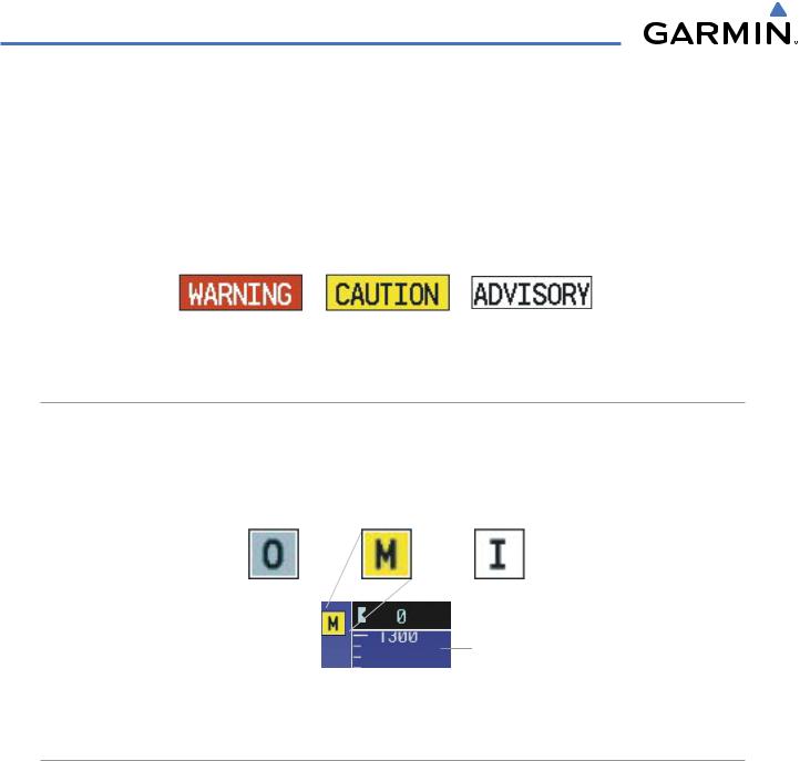
MINIMUM DESCENT ALTITUDE/DECISION HEIGHT ALERTING
For altitude awareness, a barometric Minimum Descent Altitude (MDA) or Decision Height (DH) can be set in the Timer/References Window and is reset when the power is cycled. When active, the altitude setting is displayed to the lower left of the Altimeter and with a bug at the corresponding altitude along the Altimeter (once the altitude is within the range of the tape). The following visual annunciations occur when approaching the MDA/DH:
•When the aircraft altitude descends to within 2500 feet of the MDA/DH setting, the ‘BARO MIN’ box appears with the altitude in light blue text. The bug appears on the altitude tape in light blue once in range.
•When the aircraft passes through 100 feet of the MDA/DH, the bug and text turn white.
•Once the aircraft reaches the MDA/DH, the bug and text turn yellow and the aural alert, “Minimums Minimums”, is generated.
Within 2500 feet |
Within 100 feet |
Altitude Reached |
MDA/DH
Bug
MDA/DH
Setting
Figure 2-39 MDA/DH Alerting Visual Annunciations
2-28 |
Garmin G1000 Pilot’s Guide for Cessna Nav III |
190-00498-03 Rev.A |

FLIGHT INSTRUMENTS
Setting the barometric minimum descent altitude/decision height and bug:
1)Press the TMR/REF Softkey.
2)Turn the large FMS Knob to highlight the ‘Minimums’ field (Figure 2-40).
3)Turn the small FMS Knob to select BARO. OFF is selected by default. Press the ENT Key or turn the large FMS Knob to highlight the next field.
4)Use the small FMS Knob to enter the desired altitude (from zero to 16,000 feet).
5)To remove the window, press the CLR Key or the TMR/REF Softkey.
Figure 2-40 Minimum Descent Altitude/Decision Height
Setting (Timer/References Window)
Alerting is inhibited while the aircraft is on the ground and until the aircraft reaches 150 feet above the setting for the alert. If the aircraft proceeds to climb after having reached the MDA/DH, once it reaches 50 feet above the MDA/DH, alerting is disabled.
190-00498-03 Rev.A |
Garmin G1000 Pilot’s Guide for Cessna Nav III |
2-29 |