

- •Section 1 System Overview
- •1.1 System Description
- •1.2 Line Replaceable Units (LRU)
- •1.3 G1000 Controls
- •PFD/MFD Controls
- •Audio Panel Controls
- •1.4 Secure Digital (SD) Cards
- •1.5 System Power-up
- •1.6 System Operation
- •Normal Display Operation
- •Reversionary Display Operation
- •AHRS Operation
- •G1000 System Annunciations
- •Softkey Function
- •GPS Receiver Operation
- •1.7 Accessing G1000 Functionality
- •Menus
- •MFD Page Groups
- •MFD System Pages
- •1.8 Display Backlighting
- •Automatic Adjustment
- •Manual Adjustment
- •Section 2 Flight Instruments
- •2.1 Flight Instruments
- •Airspeed Indicator
- •Attitude Indicator
- •Altimeter
- •Vertical Speed Indicator (VSI)
- •Vertical Deviation
- •Horizontal Situation Indicator (HSI)
- •Course Deviation Indicator (CDI)
- •2.2 Supplemental Flight Data
- •Outside Air Temperature
- •Wind Data
- •Vertical Navigation (VNV) Indications
- •2.3 PFD Annunciations and Alerting Functions
- •G1000 System Alerting
- •Marker Beacon Annunciations
- •Traffic Annunciation
- •TAWS Annunciations
- •Altitude Alerting
- •Low Altitude Annunciation
- •Minimum Descent Altitude/Decision Height Alerting
- •2.4 Abnormal Operations
- •Abnormal GPS Conditions
- •Unusual Attitudes
- •Section 3 Engine Indication System (EIS)
- •3.1 Engine Display
- •3.2 Lean Display
- •Normally-aspirated Aircraft
- •Turbocharged Aircraft
- •3.3 System Display
- •Section 4 audio panel and CNS
- •4.1 Overview
- •MFD/PFD Controls and Frequency Display
- •Audio Panel Controls
- •4.2 COM Operation
- •COM Transceiver Selection and Activation
- •COM Transceiver Manual Tuning
- •Quick-Tuning and Activating 121.500 MHz
- •Auto-tuning the COM Frequency
- •Frequency Spacing
- •Automatic Squelch
- •Volume
- •4.3 NAV Operation
- •NAV Radio Selection and Activation
- •NAV Receiver Manual Tuning
- •Auto-tuning a NAV Frequency from the MFD
- •Marker Beacon Receiver
- •DME Tuning (Optional)
- •4.4 GTX 33 Mode S Transponder
- •Transponder Controls
- •Transponder Mode Selection
- •Entering a Transponder Code
- •IDENT Function
- •Flight ID Reporting
- •4.5 Additional Audio Panel Functions
- •Power-Up
- •Mono/Stereo Headsets
- •Speaker
- •Intercom
- •Passenger Address (PA) System
- •Clearance Recorder and Player
- •Entertainment Inputs
- •4.6 Audio Panel Preflight Procedure
- •4.7 Abnormal Operation
- •Stuck Microphone
- •COM Tuning Failure
- •Audio Panel Fail-Safe Operation
- •Reversionary Mode
- •Section 5 Flight Management
- •5.1 Introduction
- •Navigation Status Box
- •5.2 Using Map Displays
- •Map Orientation
- •Map Range
- •Map Panning
- •Measuring Bearing and Distance
- •Topography
- •Map Symbols
- •Airways
- •Track Vector
- •Wind Vector
- •Nav Range Ring
- •Fuel Range Ring
- •5.3 Waypoints
- •Airports
- •Intersections
- •NDBs
- •VORs
- •User Waypoints
- •5.4 Airspaces
- •5.5 Direct-to-Navigation
- •5.6 Flight Planning
- •Flight Plan Creation
- •Adding Waypoints To An Existing Flight Plan
- •Adding Airways to a Flight Plan
- •Adding Procedures To A Stored Flight Plan
- •Flight Plan Storage
- •Flight Plan Editing
- •Along Track Offsets
- •Parallel Track
- •Activating a Flight Plan Leg
- •Inverting a Flight Plan
- •Flight Plan Views
- •Closest Point of FPL
- •5.7 Vertical Navigation
- •Altitude Constraints
- •5.8 Procedures
- •Departures
- •Arrivals
- •Approaches
- •5.9 Trip Planning
- •Trip Planning
- •5.10 RAIM Prediction
- •5.11 Navigating a Flight Plan
- •5.12 Abnormal Operation
- •Section 6 Hazard Avoidance
- •6.1 XM Satellite Weather
- •Activating Services
- •Using XM Satellite Weather Products
- •6.2 WX-500 Stormscope (Optional)
- •Setting Up Stormscope on the Navigation Map
- •Selecting the Stormscope Page
- •6.3 Terrain Proximity
- •Displaying Terrain Proximity Data
- •Terrain Proximity Page
- •6.4 TAWs (Optional)
- •Displaying TAWS Data
- •TAWS Page
- •TAWS Alerts
- •System Status
- •6.5 Traffic Information Service (TIS)
- •Displaying TRAFFIC Data
- •Traffic Map Page
- •TIS Alerts
- •System Status
- •6.6 Traffic Advisory System (TAS) (Optional)
- •TAS Symbology
- •Operation
- •Altitude Display
- •Traffic Map Page Display Range
- •TAS Alerts
- •System Status
- •6.7 ADS-B Traffic (Optional)
- •Section 7 Automatic Flight Control System
- •7.2 Flight Director Operation
- •Activating the Flight Director
- •AFCS Status Box
- •Command Bars
- •Flight Director Modes
- •7.3 Vertical Modes
- •Pitch Hold Mode (PIT)
- •Selected Altitude capture Mode (ALTs)
- •Altitude hold mode (alt)
- •Vertical Speed Mode (VS)
- •Flight Level Change Mode (FLC)
- •Vertical Navigation Modes (VPTH, ALTV)
- •Glidepath Mode (GP) (waas only)
- •Glideslope Mode (GS)
- •Go Around (GA) Mode
- •7.4 Lateral Modes
- •Roll Hold Mode (ROL)
- •Heading Select Mode (HDG)
- •Navigation mode (GPS, VOR, LOC)
- •Approach mode (GPS, VAPP, LOC)
- •Backcourse Mode (BC)
- •7.5 Autopilot Operation
- •Engaging the Autopilot
- •Control Wheel Steering
- •Disengaging the Autopilot
- •7.6 Example Procedures
- •Departure
- •Intercepting a VOR Radial
- •Flying a Flight Plan/GPS Course
- •Descent
- •Approach
- •Go Around/Missed Approach
- •7.7 AFCS Annunciations and Alerts
- •AFCS Status Alerts
- •Overspeed Protection
- •Section 8 Additional Features
- •8.1 SafeTaxi
- •SafeTaxi Cycle Number and Revision
- •8.2 ChartView
- •ChartView Softkeys
- •Terminal Procedures Charts
- •Chart Options
- •Day/Night View
- •ChartView Cycle Number and Expiration Date
- •8.3 FliteCharts
- •FliteCharts Softkeys
- •Terminal Procedures Charts
- •Chart Options
- •Day/Night View
- •FliteCharts Cycle Number and Expiration Date
- •8.4 XM Radio Entertainment (Optional)
- •Activating XM Satellite Radio Services
- •Using XM Radio
- •Automatic Audio Muting
- •8.5 Scheduler
- •8.5 Abnormal Operation
- •Annunciations and Alerts
- •Alert Level Definitions
- •Nav III Aircraft Alerts
- •CO Guardian Messages
- •G1000 System Annunciations
- •Other G1000 Aural Alerts
- •G1000 System Message Advisories
- •AFCS Alerts
- •TAWS ALERTS
- •TAWS System Status Annunciations
- •SD Card Use
- •Jeppesen Databases
- •Garmin Databases
- •Glossary
- •Frequently Asked Questions
- •General TIS Information
- •Introduction
- •TIS vs. TAS/TCAS
- •TIS Limitations
- •Map Symbols
- •Index
ADDITIONAL FEATURES
DAY/NIGHT VIEW
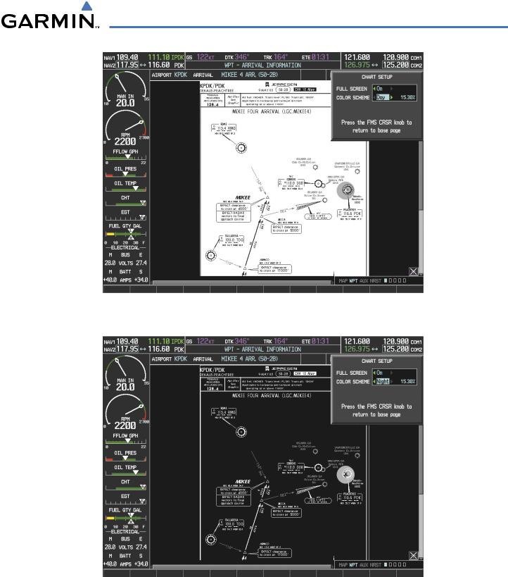
ChartView can be displayed on a white or black background for day or night viewing. The Day View offers a better presentation in a bright environment. The Night View gives a better presentation for viewing in a dark environment. When the CHART SETUP Box is selected the G1000 softkeys are blank.
Selecting Day, Night, or Automatic View:
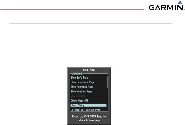
1)While viewing a terminal chart press the MENU Key to display the Page Menu OPTIONS.
2)Turn the large FMS Knob to highlight the Chart Setup Menu Option and press the ENT Key.
Figure 8-29 Waypoint Information Page, OPTIONS Menu
3)Turn the large FMS Knob to move to the COLOR SCHEME Option (Figure 8-30).
4)Turn the small FMS Knob to choose between Day,Auto, and Night Options.
5)If Auto Mode is selected, turn the large FMS Knob to select the percentage field. Use the small FMS Knob to change the percentage value. The percentage value is the day/night crossover point based on the percentage of backlighting intensity. For example, if the value is set to 15%, the day/night display changes when the display backlight reaches 15% of full brightness.
The display must be changed in order for the new setting to become active. This may be accomplished by selecting another page or changing the display range.
6)Press the FMS Knob when finished to remove the Chart Setup Menu.
8-24 |
Garmin G1000 Pilot’s Guide for Cessna Nav III |
190-00498-03 Rev A |
ADDITIONAL FEATURES
Figure 8-30 Arrival Information Page, Day View
Figure 8-31 Arrival Information Page, Night View
190-00498-03 Rev A |
Garmin G1000 Pilot’s Guide for Cessna Nav III |
8-25 |
ADDITIONAL FEATURES
CHARTVIEW CYCLE NUMBER AND EXPIRATION DATE
The ChartView database is revised every 14 days. Charts are still viewable during a period that extends from the cycle expiration date to the disables date. ChartView is disabled 70 days after the expiration date and is no longer available for viewing upon reaching the disables date. When turning on the G1000, the Power-up Page indicates any of nine different possible criteria for ChartView availability. See the table below for the various ChartView Power-up Page displays and the definition of each.
Power-up Page Display |
Definition |
|
Blank Line. G1000 system is not configured for ChartView. Contact |
|
a Garmin-authorized service center for configuration. |
|
System is configured for ChartView but no chart database is |
|
installed. Contact Jeppesen for a ChartView database. |
|
Normal operation. ChartView database is valid and within current |
|
cycle. |
|
ChartView database is within 1 week after expiration date. A new |
|
cycle is available for update. |
|
ChartView database is beyond 1 week after expiration date, but still |
|
within the 70 day viewing period. |
|
ChartView database has timed out. Database is beyond 70 days |
|
after expiration date. ChartView database is no longer available for |
|
viewing. |
|
System time is not available. GPS satellite data is unknown or |
|
G1000 has not yet locked onto satellites. Check database cycle |
|
number for effectivity. |
|
System is verifying chart database when new cycle is installed for the |
|
first time. |
|
After verifying, chart database is found to be corrupt. ChartView is |
|
not available. |
Table 8-1 ChartView Power-up Page Annunciations and Definitions
8-26 |
Garmin G1000 Pilot’s Guide for Cessna Nav III |
190-00498-03 Rev A |
ADDITIONAL FEATURES
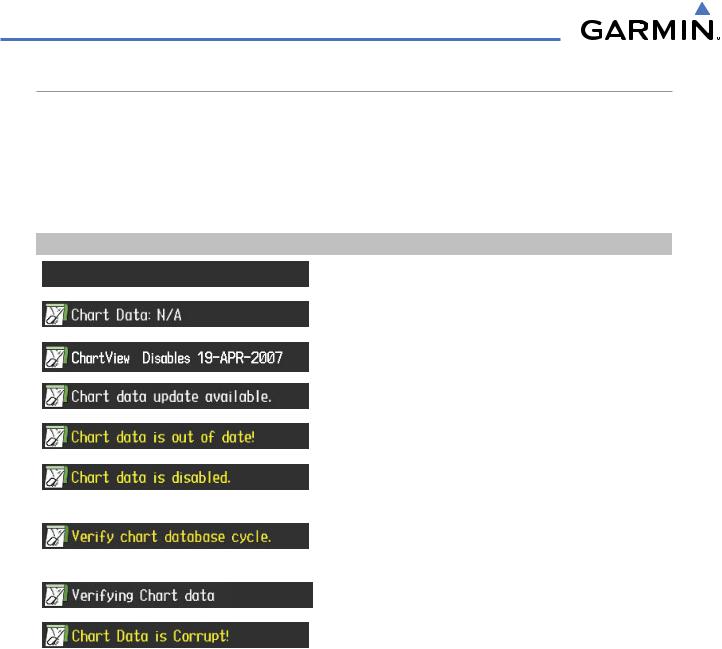
Examples of four possible Power-up Page conditions are shown here. ChartView Disables plus a date in white, indicates chart data is current. This indication for normal operation shows how long the charts may be viewed. Chart data update available. in white, indicates the chart data cycle has expired within the past week and the next chart cycle is available. Chart data is out of date! in yellow, indicates charts are still viewable, but approaching the disable date. Chart data is disabled. in yellow, indicates the chart cycle has been disabled and is no longer viewable.
ChartView Database is |
Chart Cycle has Expired, |
Current and Available |
Next Cycle is Available |
Chart Cycle has Expired but is Still Viewable |
Chart Cycle is No |
for 70 Days from Expiration Date |
Longer Viewable |
Figure 8-32 Examples of Power-up Page, ChartView Database
190-00498-03 Rev A |
Garmin G1000 Pilot’s Guide for Cessna Nav III |
8-27 |
ADDITIONAL FEATURES
 NOTE: A subdued softkey label indicates the function is disabled.
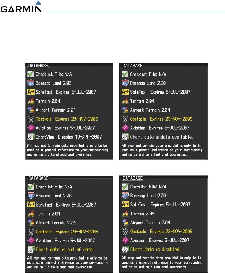
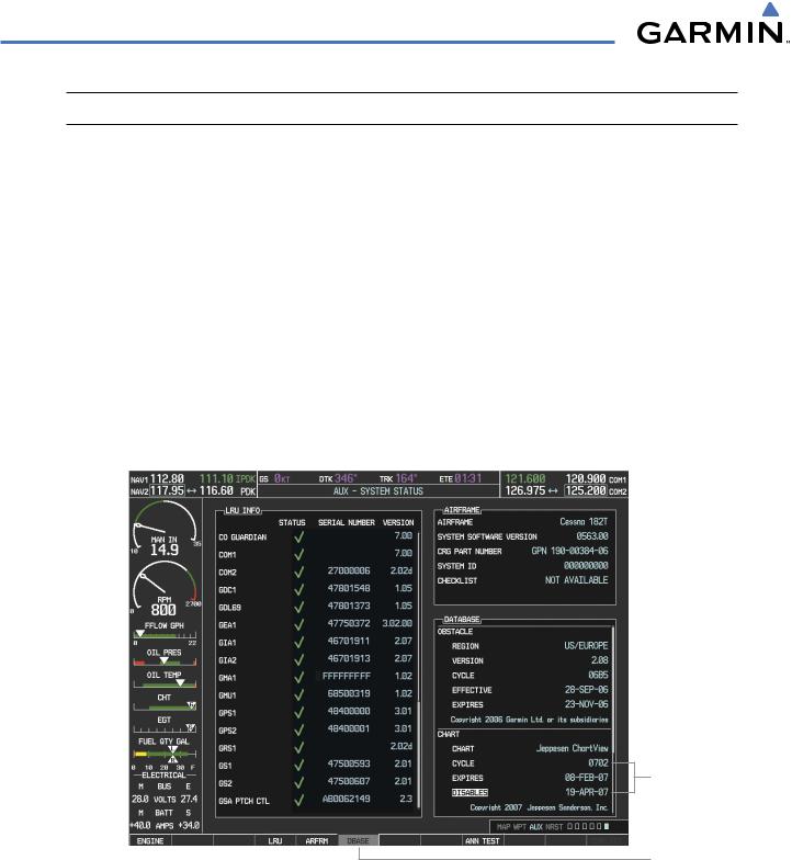
The ChartView time critical information can also be found on the AUX - System Status page. The database CYCLE number, EXPIRES, and DISABLES dates of the ChartView subscription appear in either blue or yellow text. When the ChartView EXPIRES date is reached, ChartView becomes inoperative 70 days later. This is shown as the DISABLES date. When the DISABLES date is reached, charts are no longer available for viewing. The SHW CHRT Softkey label then appears subdued and is disabled until a revised issue of ChartView is installed.
Press the DBASE Softkey for scrolling through the database information. Scroll through the database with the FMS knob or ENT Key.
The ChartView database cycle number shown in the figure, 0702, is deciphered as follows: 07 – Indicates the year 2007
02 – Indicates the 2nd issue of the ChartView database for the year
The EXPIRES date 08–FEB–07 is the date that this database should be replaced with the next issue. The DISABLES date 19–APR–07 is the date that this database becomes inoperative.
ChartView
Data
DBASE Softkey
Selected
Figure 8-33 AUX – System Status Page, ChartView Current and Available
The ChartView database is provided directly from Jeppesen. Refer to Updating Jeppesen Databases in Appendix B for instructions on revising the ChartView database.
8-28 |
Garmin G1000 Pilot’s Guide for Cessna Nav III |
190-00498-03 Rev A |
ADDITIONAL FEATURES
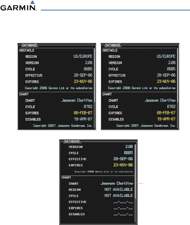
The other three possible AUX - System Status page conditions are shown here. The EXPIRES date, in yellow, is the revision date for the next database cycle. The DISABLES date, in yellow, is the date that this database cycle is no longer viewable. REGION and CYCLE NOT AVAILABLE in blue, indicate that no ChartView data is available on the database card or no database card is inserted.
ChartView Database has Expired, but is not Disabled |
ChartView Database is Disabled |
System is
Configured for
ChartView but
Database is not
Available
ChartView Database is Not Available
Figure 8-34 AUX – System Status Page, ChartView Expired, ChartView Disabled, ChartView Not Available
190-00498-03 Rev A |
Garmin G1000 Pilot’s Guide for Cessna Nav III |
8-29 |