

- •Section 1 System Overview
- •1.1 System Description
- •1.2 Line Replaceable Units (LRU)
- •1.3 G1000 Controls
- •PFD/MFD Controls
- •Audio Panel Controls
- •1.4 Secure Digital (SD) Cards
- •1.5 System Power-up
- •1.6 System Operation
- •Normal Display Operation
- •Reversionary Display Operation
- •AHRS Operation
- •G1000 System Annunciations
- •Softkey Function
- •GPS Receiver Operation
- •1.7 Accessing G1000 Functionality
- •Menus
- •MFD Page Groups
- •MFD System Pages
- •1.8 Display Backlighting
- •Automatic Adjustment
- •Manual Adjustment
- •Section 2 Flight Instruments
- •2.1 Flight Instruments
- •Airspeed Indicator
- •Attitude Indicator
- •Altimeter
- •Vertical Speed Indicator (VSI)
- •Vertical Deviation
- •Horizontal Situation Indicator (HSI)
- •Course Deviation Indicator (CDI)
- •2.2 Supplemental Flight Data
- •Outside Air Temperature
- •Wind Data
- •Vertical Navigation (VNV) Indications
- •2.3 PFD Annunciations and Alerting Functions
- •G1000 System Alerting
- •Marker Beacon Annunciations
- •Traffic Annunciation
- •TAWS Annunciations
- •Altitude Alerting
- •Low Altitude Annunciation
- •Minimum Descent Altitude/Decision Height Alerting
- •2.4 Abnormal Operations
- •Abnormal GPS Conditions
- •Unusual Attitudes
- •Section 3 Engine Indication System (EIS)
- •3.1 Engine Display
- •3.2 Lean Display
- •Normally-aspirated Aircraft
- •Turbocharged Aircraft
- •3.3 System Display
- •Section 4 audio panel and CNS
- •4.1 Overview
- •MFD/PFD Controls and Frequency Display
- •Audio Panel Controls
- •4.2 COM Operation
- •COM Transceiver Selection and Activation
- •COM Transceiver Manual Tuning
- •Quick-Tuning and Activating 121.500 MHz
- •Auto-tuning the COM Frequency
- •Frequency Spacing
- •Automatic Squelch
- •Volume
- •4.3 NAV Operation
- •NAV Radio Selection and Activation
- •NAV Receiver Manual Tuning
- •Auto-tuning a NAV Frequency from the MFD
- •Marker Beacon Receiver
- •DME Tuning (Optional)
- •4.4 GTX 33 Mode S Transponder
- •Transponder Controls
- •Transponder Mode Selection
- •Entering a Transponder Code
- •IDENT Function
- •Flight ID Reporting
- •4.5 Additional Audio Panel Functions
- •Power-Up
- •Mono/Stereo Headsets
- •Speaker
- •Intercom
- •Passenger Address (PA) System
- •Clearance Recorder and Player
- •Entertainment Inputs
- •4.6 Audio Panel Preflight Procedure
- •4.7 Abnormal Operation
- •Stuck Microphone
- •COM Tuning Failure
- •Audio Panel Fail-Safe Operation
- •Reversionary Mode
- •Section 5 Flight Management
- •5.1 Introduction
- •Navigation Status Box
- •5.2 Using Map Displays
- •Map Orientation
- •Map Range
- •Map Panning
- •Measuring Bearing and Distance
- •Topography
- •Map Symbols
- •Airways
- •Track Vector
- •Wind Vector
- •Nav Range Ring
- •Fuel Range Ring
- •5.3 Waypoints
- •Airports
- •Intersections
- •NDBs
- •VORs
- •User Waypoints
- •5.4 Airspaces
- •5.5 Direct-to-Navigation
- •5.6 Flight Planning
- •Flight Plan Creation
- •Adding Waypoints To An Existing Flight Plan
- •Adding Airways to a Flight Plan
- •Adding Procedures To A Stored Flight Plan
- •Flight Plan Storage
- •Flight Plan Editing
- •Along Track Offsets
- •Parallel Track
- •Activating a Flight Plan Leg
- •Inverting a Flight Plan
- •Flight Plan Views
- •Closest Point of FPL
- •5.7 Vertical Navigation
- •Altitude Constraints
- •5.8 Procedures
- •Departures
- •Arrivals
- •Approaches
- •5.9 Trip Planning
- •Trip Planning
- •5.10 RAIM Prediction
- •5.11 Navigating a Flight Plan
- •5.12 Abnormal Operation
- •Section 6 Hazard Avoidance
- •6.1 XM Satellite Weather
- •Activating Services
- •Using XM Satellite Weather Products
- •6.2 WX-500 Stormscope (Optional)
- •Setting Up Stormscope on the Navigation Map
- •Selecting the Stormscope Page
- •6.3 Terrain Proximity
- •Displaying Terrain Proximity Data
- •Terrain Proximity Page
- •6.4 TAWs (Optional)
- •Displaying TAWS Data
- •TAWS Page
- •TAWS Alerts
- •System Status
- •6.5 Traffic Information Service (TIS)
- •Displaying TRAFFIC Data
- •Traffic Map Page
- •TIS Alerts
- •System Status
- •6.6 Traffic Advisory System (TAS) (Optional)
- •TAS Symbology
- •Operation
- •Altitude Display
- •Traffic Map Page Display Range
- •TAS Alerts
- •System Status
- •6.7 ADS-B Traffic (Optional)
- •Section 7 Automatic Flight Control System
- •7.2 Flight Director Operation
- •Activating the Flight Director
- •AFCS Status Box
- •Command Bars
- •Flight Director Modes
- •7.3 Vertical Modes
- •Pitch Hold Mode (PIT)
- •Selected Altitude capture Mode (ALTs)
- •Altitude hold mode (alt)
- •Vertical Speed Mode (VS)
- •Flight Level Change Mode (FLC)
- •Vertical Navigation Modes (VPTH, ALTV)
- •Glidepath Mode (GP) (waas only)
- •Glideslope Mode (GS)
- •Go Around (GA) Mode
- •7.4 Lateral Modes
- •Roll Hold Mode (ROL)
- •Heading Select Mode (HDG)
- •Navigation mode (GPS, VOR, LOC)
- •Approach mode (GPS, VAPP, LOC)
- •Backcourse Mode (BC)
- •7.5 Autopilot Operation
- •Engaging the Autopilot
- •Control Wheel Steering
- •Disengaging the Autopilot
- •7.6 Example Procedures
- •Departure
- •Intercepting a VOR Radial
- •Flying a Flight Plan/GPS Course
- •Descent
- •Approach
- •Go Around/Missed Approach
- •7.7 AFCS Annunciations and Alerts
- •AFCS Status Alerts
- •Overspeed Protection
- •Section 8 Additional Features
- •8.1 SafeTaxi
- •SafeTaxi Cycle Number and Revision
- •8.2 ChartView
- •ChartView Softkeys
- •Terminal Procedures Charts
- •Chart Options
- •Day/Night View
- •ChartView Cycle Number and Expiration Date
- •8.3 FliteCharts
- •FliteCharts Softkeys
- •Terminal Procedures Charts
- •Chart Options
- •Day/Night View
- •FliteCharts Cycle Number and Expiration Date
- •8.4 XM Radio Entertainment (Optional)
- •Activating XM Satellite Radio Services
- •Using XM Radio
- •Automatic Audio Muting
- •8.5 Scheduler
- •8.5 Abnormal Operation
- •Annunciations and Alerts
- •Alert Level Definitions
- •Nav III Aircraft Alerts
- •CO Guardian Messages
- •G1000 System Annunciations
- •Other G1000 Aural Alerts
- •G1000 System Message Advisories
- •AFCS Alerts
- •TAWS ALERTS
- •TAWS System Status Annunciations
- •SD Card Use
- •Jeppesen Databases
- •Garmin Databases
- •Glossary
- •Frequently Asked Questions
- •General TIS Information
- •Introduction
- •TIS vs. TAS/TCAS
- •TIS Limitations
- •Map Symbols
- •Index

AUTOMATIC FLIGHT CONTROL SYSTEM
FLYING A FLIGHT PLAN/GPS COURSE
 NOTE: Changing the navigation source cancels Navigation Mode and causes the flight director to revert back to Roll Hold Mode (wings rolled level).
As the aircraft closes on Salina VOR, GPS is used to navigate the next leg, airway V244. The aircraft is currently tracking inbound on Airway V4.
Flying a GPS flight plan:
1)Transition from VOR to GPS Navigation Mode:
a)Press the CDI Softkey until GPS is the selected navigation source.
b)Press the NAV Key to activate GPS Navigation Mode. The autopilot guides the aircraft along the active flight plan leg.
2)Following the flight plan, the autopilot continues to steer the aircraft under GPS guidance. Note that in GPS Navigation Mode, course changes defined by the flight plan are automatically made without pilot action required.
33
30
27
4
2
21
0
3
6
o 076 
3 |
0 |
|
27
o  260
260
V 244
33
3
0
|
|
|
3 |
|
|
|
|
|
6 |
|
|
|
|
o |
|
|
|
de |
075 |
|
|
|
|
|
|
|
VMo |
|
|
GPS |
NA |
|
|
|
|
|
|
|
|
Salina |
|
|
9 |
|
|
|
|
||
VOR |
|
|
|
|
(SLN) |
|
|
|
|
Hays |
9 |
24 |
|
VOR |
|
2 |
1 |
|
|
||
(HYS) |
|
|
|
|
1 |
|
12 |
2 |
15 |
|
||
|
18 |
|
|
|
|
1 |
|
|
5 |
|
|
18
Figure 7-33 Transition to GPS Flight Plan
V4 2
1
|
e |
|
VMod |
RNA |
|
VO |
|
7-36 |
Garmin G1000 Pilot’s Guide for Cessna Nav III |
190-00498-03 Rev.A |
AUTOMATIC FLIGHT CONTROL SYSTEM
DESCENT
While flying the arrival procedure, the aircraft is cleared for descent in preparation for the approach to KCOS. Three methods are presented for descent:
•Flight Level Change descent – Flight Level Change Mode can be used to descend to the Selected Altitude at a constant airspeed. This descent method does not account for flight plan waypoint altitude constraints.
•Vertical Path Tracking descent – Vertical Path Tracking Mode is used to follow the vertical descent path defined in the GPS flight plan. Altitude constraints correspond to waypoints in the flight plan. Before VNV flight control can provide vertical profile guidance, a VNV flight plan must be entered and enabled.
•Non-path descent in a VNV scenario – A VNV flight plan is entered and enabled, however Pitch Hold, Vertical Speed, or Flight Level Change Mode can be used to descend to the VNV Target Altitude prior to reaching the planned TOD. Flight Level Change Mode is used in the example.
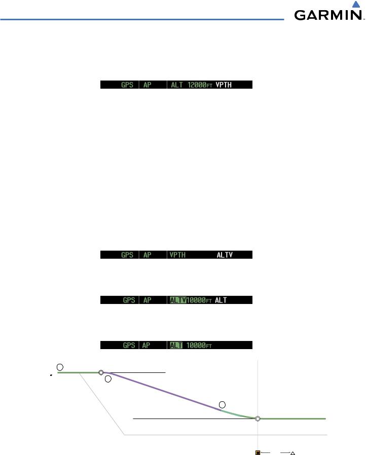
Flight Level Change descent:
1)Select Flight Level Change Mode:
a)Using the ALT Knob, set the Selected Altitude to 10,000 feet.
b)Press the FLC Key to activate Flight Level Change Mode. The annunciation ‘FLC’ appears next to the Airspeed Reference, which defaults to the current aircraft airspeed. Selected Altitude Capture Mode is armed automatically.
2)Use the NOSE UP/NOSE DN keys or push the CWS Button while hand-flying the aircraft to adjust the commanded airspeed while maintaining the same power, or reduce power to allow descent in Flight Level Change Mode while the autopilot maintains the current airspeed.
3)As the aircraft nears the Selected Altitude, the flight director transitions to Selected Altitude Capture Mode, indicated by the green ‘ALTS’ annunciation flashing for up to 10 seconds.
The green ‘ALT’ annunciation flashes for up to 10 seconds upon reaching 50 feet from the SelectedAltitude; the autopilot transitions to Altitude Hold Mode and levels the aircraft.
1 |
|
Cruise Altitude of 12,000 MSL |
|
|
|
|
ALT Mode |
2 |
|
|
|
|
|
FLC |
|
|
Mode |
3
Selected Altitude of 10,000 MSL
ALT Mode
Figure 7-34 FLC Descent
190-00498-03 Rev.A |
Garmin G1000 Pilot’s Guide for Cessna Nav III |
7-37 |
AUTOMATIC FLIGHT CONTROL SYSTEM
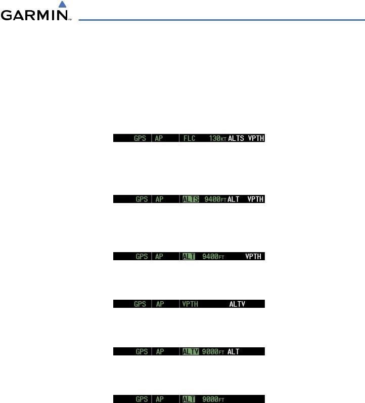
Vertical Path Tracking descent to VNV Target Altitude:
1)Select VNV flight control:
a)Press the VNV Key to arm Vertical Path Tracking Mode. The white annunciation ‘VPTH’ appears.
b)Using the ALT Knob, set the Selected Altitude below the flight plan’s VNV Target Altitude of 10,000 feet.
If the Selected Altitude is not at least 75 ft below the VNV Target Altitude, the flight director captures the Selected Altitude rather than the VNV Target Altitude once Vertical Path Tracking Mode becomes active (ALTS is armed rather than ALTV).
c)If Vertical Path Tracking Mode is armed more than 5 minutes prior to descent path capture, acknowledgment is required for the flight director to transition from Altitude Hold to Vertical Path Tracking Mode. To proceed with descent path capture if the white ‘VPTH’ annunciation begins flashing, do one of the following
• Press the VNV Key |
• Turn the ALT Knob to adjust the Selected Altitude |
If the descent is not confirmed by the time of interception,Vertical Path Tracking Mode remains armed and the descent is not captured.
2)When the top of descent (TOD) is reached, the flight director transitions to Vertical Path Tracking Mode and begins the descent to the VNV Target Altitude. Intention to capture the VNV Target Altitude is indicated by the white ‘ALTV’ annunciation.
3)As the aircraft nears theVNVTargetAltitude,the flight director transitions toVNVTargetAltitude Capture Mode, indicated by the green ‘ALTV’ annunciation flashing for up to 10 seconds.
The green ‘ALT’ annunciation flashes for up to 10 seconds upon reaching 50 feet from the VNV Target Altitude; the autopilot transitions to Altitude Hold Mode and levels the aircraft at the vertical waypoint.
1 ALT Mode |
TOD |
Cruise Altitude of 12,000 MSL |
|
||
|
|
2 |
|
|
VPTH |
|
|
Mode |
3
VNAV Target Altitude of 10,000 MSL
BOD |
ALT Mode |
|
Selected Altitude (set below VNAV Target Altitude)
OPSHN
3 nm
Figure 7-35 VPTH Descent
7-38 |
Garmin G1000 Pilot’s Guide for Cessna Nav III |
190-00498-03 Rev.A |
AUTOMATIC FLIGHT CONTROL SYSTEM
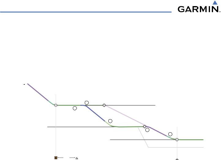
Non-path descent using Flight Level Change Mode:
1)Using Flight Level Change Mode, command a non-path descent to an intermediate altitude above the nextVNV flight plan altitude:
a)Using the ALT Knob, set the Selected Altitude below the current aircraft altitude to an altitude (in this case, 9,400 feet) at which to level off between VNV flight plan altitudes.
b)Press the FLC Key before the plannedTOD during an altitude hold whileVPTH is armed. TheAirspeed Reference defaults to the current aircraft airspeed. Vertical Path Tracking and Selected Altitude Capture Mode are armed automatically.
2)Reduce power to allow descent in Flight Level Change Mode. The autopilot maintains the Airspeed Reference.
3)As the aircraft nears the Selected Altitude, the flight director transitions to Selected Altitude Capture Mode, indicated by the green ‘ALTS’ annunciation flashing for up to 10 seconds.
The green ‘ALT’ annunciation flashes for up to 10 seconds upon reaching 50 feet from the SelectedAltitude; the autopilot transitions to Altitude Hold Mode and levels the aircraft. After leveling off reset, Selected Altitude at or below 9,000 ft.
4)When the next TOD is reached, Vertical Path Tracking becomes active (may require acknowledgment to allow descent path capture).
5)As the aircraft nears theVNVTargetAltitude,the flight director transitions toVNVTargetAltitude Capture Mode, indicated by the green ‘ALTV’ annunciation flashing for up to 10 seconds.
The green ‘ALT’ annunciation flashes for up to 10 seconds upon reaching 50 feet from the VNV Target Altitude; the autopilot transitions to Altitude Hold Mode and levels the aircraft at the vertical waypoint.
190-00498-03 Rev.A |
Garmin G1000 Pilot’s Guide for Cessna Nav III |
7-39 |
AUTOMATIC FLIGHT CONTROL SYSTEM
VPTH |
Mode |
|
BOD |
2 |
|
ALT Mode 1 |
FLC |
|
|
Mode |
|
|
|
Selected Altitude of 9,400 MSL
Planned |
|
TOD |
VNAV Target Altitude of 10,000 MSL |
|
|
Planned |
Descent P |
|
|
|
|
|
|
|
|
|
3 |
|
ath |
|
|
|
ALT Mode |
TOD |
|
|
||
|
VPTH |
|
|||
|
|
|
|||
|
|
|
4 |
Mode |
|
|
|
|
|
||
|
|
|
|
|
|
VNAV Target Altitude of 9,000 MSL |
|
||||
5
BOD ALT Mode
Selected Altitude
3 nm |
OPSHN |
HABUK |
|
||
|
|
Figure 7-36 Non-path Descent
7-40 |
Garmin G1000 Pilot’s Guide for Cessna Nav III |
190-00498-03 Rev.A |