

- •Section 1 System Overview
- •1.1 System Description
- •1.2 Line Replaceable Units (LRU)
- •1.3 G1000 Controls
- •PFD/MFD Controls
- •Audio Panel Controls
- •1.4 Secure Digital (SD) Cards
- •1.5 System Power-up
- •1.6 System Operation
- •Normal Display Operation
- •Reversionary Display Operation
- •AHRS Operation
- •G1000 System Annunciations
- •Softkey Function
- •GPS Receiver Operation
- •1.7 Accessing G1000 Functionality
- •Menus
- •MFD Page Groups
- •MFD System Pages
- •1.8 Display Backlighting
- •Automatic Adjustment
- •Manual Adjustment
- •Section 2 Flight Instruments
- •2.1 Flight Instruments
- •Airspeed Indicator
- •Attitude Indicator
- •Altimeter
- •Vertical Speed Indicator (VSI)
- •Vertical Deviation
- •Horizontal Situation Indicator (HSI)
- •Course Deviation Indicator (CDI)
- •2.2 Supplemental Flight Data
- •Outside Air Temperature
- •Wind Data
- •Vertical Navigation (VNV) Indications
- •2.3 PFD Annunciations and Alerting Functions
- •G1000 System Alerting
- •Marker Beacon Annunciations
- •Traffic Annunciation
- •TAWS Annunciations
- •Altitude Alerting
- •Low Altitude Annunciation
- •Minimum Descent Altitude/Decision Height Alerting
- •2.4 Abnormal Operations
- •Abnormal GPS Conditions
- •Unusual Attitudes
- •Section 3 Engine Indication System (EIS)
- •3.1 Engine Display
- •3.2 Lean Display
- •Normally-aspirated Aircraft
- •Turbocharged Aircraft
- •3.3 System Display
- •Section 4 audio panel and CNS
- •4.1 Overview
- •MFD/PFD Controls and Frequency Display
- •Audio Panel Controls
- •4.2 COM Operation
- •COM Transceiver Selection and Activation
- •COM Transceiver Manual Tuning
- •Quick-Tuning and Activating 121.500 MHz
- •Auto-tuning the COM Frequency
- •Frequency Spacing
- •Automatic Squelch
- •Volume
- •4.3 NAV Operation
- •NAV Radio Selection and Activation
- •NAV Receiver Manual Tuning
- •Auto-tuning a NAV Frequency from the MFD
- •Marker Beacon Receiver
- •DME Tuning (Optional)
- •4.4 GTX 33 Mode S Transponder
- •Transponder Controls
- •Transponder Mode Selection
- •Entering a Transponder Code
- •IDENT Function
- •Flight ID Reporting
- •4.5 Additional Audio Panel Functions
- •Power-Up
- •Mono/Stereo Headsets
- •Speaker
- •Intercom
- •Passenger Address (PA) System
- •Clearance Recorder and Player
- •Entertainment Inputs
- •4.6 Audio Panel Preflight Procedure
- •4.7 Abnormal Operation
- •Stuck Microphone
- •COM Tuning Failure
- •Audio Panel Fail-Safe Operation
- •Reversionary Mode
- •Section 5 Flight Management
- •5.1 Introduction
- •Navigation Status Box
- •5.2 Using Map Displays
- •Map Orientation
- •Map Range
- •Map Panning
- •Measuring Bearing and Distance
- •Topography
- •Map Symbols
- •Airways
- •Track Vector
- •Wind Vector
- •Nav Range Ring
- •Fuel Range Ring
- •5.3 Waypoints
- •Airports
- •Intersections
- •NDBs
- •VORs
- •User Waypoints
- •5.4 Airspaces
- •5.5 Direct-to-Navigation
- •5.6 Flight Planning
- •Flight Plan Creation
- •Adding Waypoints To An Existing Flight Plan
- •Adding Airways to a Flight Plan
- •Adding Procedures To A Stored Flight Plan
- •Flight Plan Storage
- •Flight Plan Editing
- •Along Track Offsets
- •Parallel Track
- •Activating a Flight Plan Leg
- •Inverting a Flight Plan
- •Flight Plan Views
- •Closest Point of FPL
- •5.7 Vertical Navigation
- •Altitude Constraints
- •5.8 Procedures
- •Departures
- •Arrivals
- •Approaches
- •5.9 Trip Planning
- •Trip Planning
- •5.10 RAIM Prediction
- •5.11 Navigating a Flight Plan
- •5.12 Abnormal Operation
- •Section 6 Hazard Avoidance
- •6.1 XM Satellite Weather
- •Activating Services
- •Using XM Satellite Weather Products
- •6.2 WX-500 Stormscope (Optional)
- •Setting Up Stormscope on the Navigation Map
- •Selecting the Stormscope Page
- •6.3 Terrain Proximity
- •Displaying Terrain Proximity Data
- •Terrain Proximity Page
- •6.4 TAWs (Optional)
- •Displaying TAWS Data
- •TAWS Page
- •TAWS Alerts
- •System Status
- •6.5 Traffic Information Service (TIS)
- •Displaying TRAFFIC Data
- •Traffic Map Page
- •TIS Alerts
- •System Status
- •6.6 Traffic Advisory System (TAS) (Optional)
- •TAS Symbology
- •Operation
- •Altitude Display
- •Traffic Map Page Display Range
- •TAS Alerts
- •System Status
- •6.7 ADS-B Traffic (Optional)
- •Section 7 Automatic Flight Control System
- •7.2 Flight Director Operation
- •Activating the Flight Director
- •AFCS Status Box
- •Command Bars
- •Flight Director Modes
- •7.3 Vertical Modes
- •Pitch Hold Mode (PIT)
- •Selected Altitude capture Mode (ALTs)
- •Altitude hold mode (alt)
- •Vertical Speed Mode (VS)
- •Flight Level Change Mode (FLC)
- •Vertical Navigation Modes (VPTH, ALTV)
- •Glidepath Mode (GP) (waas only)
- •Glideslope Mode (GS)
- •Go Around (GA) Mode
- •7.4 Lateral Modes
- •Roll Hold Mode (ROL)
- •Heading Select Mode (HDG)
- •Navigation mode (GPS, VOR, LOC)
- •Approach mode (GPS, VAPP, LOC)
- •Backcourse Mode (BC)
- •7.5 Autopilot Operation
- •Engaging the Autopilot
- •Control Wheel Steering
- •Disengaging the Autopilot
- •7.6 Example Procedures
- •Departure
- •Intercepting a VOR Radial
- •Flying a Flight Plan/GPS Course
- •Descent
- •Approach
- •Go Around/Missed Approach
- •7.7 AFCS Annunciations and Alerts
- •AFCS Status Alerts
- •Overspeed Protection
- •Section 8 Additional Features
- •8.1 SafeTaxi
- •SafeTaxi Cycle Number and Revision
- •8.2 ChartView
- •ChartView Softkeys
- •Terminal Procedures Charts
- •Chart Options
- •Day/Night View
- •ChartView Cycle Number and Expiration Date
- •8.3 FliteCharts
- •FliteCharts Softkeys
- •Terminal Procedures Charts
- •Chart Options
- •Day/Night View
- •FliteCharts Cycle Number and Expiration Date
- •8.4 XM Radio Entertainment (Optional)
- •Activating XM Satellite Radio Services
- •Using XM Radio
- •Automatic Audio Muting
- •8.5 Scheduler
- •8.5 Abnormal Operation
- •Annunciations and Alerts
- •Alert Level Definitions
- •Nav III Aircraft Alerts
- •CO Guardian Messages
- •G1000 System Annunciations
- •Other G1000 Aural Alerts
- •G1000 System Message Advisories
- •AFCS Alerts
- •TAWS ALERTS
- •TAWS System Status Annunciations
- •SD Card Use
- •Jeppesen Databases
- •Garmin Databases
- •Glossary
- •Frequently Asked Questions
- •General TIS Information
- •Introduction
- •TIS vs. TAS/TCAS
- •TIS Limitations
- •Map Symbols
- •Index

HAZARD AVOIDANCE
6.3 TERRAIN PROXIMITY
WARNING: Do not use Terrain Proximity information for primary terrain avoidance. Terrain Proximity is intended only to enhance situational awareness.
 NOTE: Terrain data is not displayed when the aircraft latitude is greater than 75° North or 60° South.
G1000 Terrain Proximity is a terrain awareness system that does not comply with TSO-C151b certification standards. It increases situational awareness and aids in reducing controlled flight into terrain (CFIT). Do not confuse Terrain Proximity with Terrain Awareness and Warning System (TAWS). TAWS is more sophisticated and robust, and it is TSO-C151b certified. Terrain Proximity does not provide warning annunciations or voice alerts. It only provides color indications on map displays when terrain and obstacles are within a certain altitude threshold from the aircraft. Although the terrain and obstacle color map displays are the same, TAWS uses more sophisticated algorithms to assess aircraft distance from terrain and obstacles.
Terrain Proximity requires the following components to operate properly:
•Valid 3-D GPS position
•Valid terrain/obstacle database
Terrain Proximity displays altitudes of terrain and obstructions relative to the aircraft position and altitude with reference to a database that may contain inaccuracies. Terrain and obstructions are shown only if they are in the database. Terrain and obstacle information should be used as an aid to situational awareness. They should never be used to navigate or maneuver around terrain.
Note that all obstructions may not be available in the terrain and obstacle database. No terrain and obstacle information is shown without a valid 3-D GPS position.
The G1000 GPS receiver provides the horizontal position and altitude. GPS altitude is derived from satellite position. GPS altitude is then converted to a mean sea level (MSL)-based altitude (GPS-MSL altitude) and is used to determine terrain and obstacle proximity. GPS-MSL altitude accuracy is affected by satellite geometry, but is not subject to variations in pressure and temperature that normally affect pressure altitude sensors. GPS-MSL altitude does not require local altimeter settings to determine MSL altitude. It is a widely-used MSL altitude source.
TerrainandobstacledatabasesarereferencedtoMSL. UsingtheGPSpositionandaltitude,theTerrainProximity feature portrays a 2-D picture of the surrounding terrain and obstacles relative to the position and altitude of the aircraft. GPS position and GPS-MSL altitude are used to calculate and predict the aircraft’s flight path in relation to the surrounding terrain and obstacles. In this way, the pilot can view predicted dangerous terrain and obstacle conditions.
190-00498-03 Rev.A |
Garmin G1000 Pilot’s Guide for Cessna Nav III |
6-31 |

HAZARD AVOIDANCE
DISPLAYING TERRAIN PROXIMITY DATA
The symbols and colors in Figure 6-44 and Table 6-4 are used to represent obstacles and aircraft altitude when the Terrain Proximity Page is selected for display. Terrain Proximity uses black, yellow, and red to represent terrain information relative to aircraft altitude. The color of each obstacle is associated with the altitude of the aircraft.
|
|
Terrain Above Aircraft Altitude |
|
|
Aircraft Altitude |
Red terrain is above |
|
100 ft Threshold |
|
or within 100 ft below |
|
|
the aircraft altitude |
||
1000 ft |
|
|
|
|
Yellow terrain is between 100 ft and 1000 ft below the aircraft altitude |
||
|
Black terrain is more than 1000 ft below the aircraft altitude |
||
Figure 6-44 Terrain Altitude/Color Correlation for Terrain Proximity |
|||
Unlighted Obstacle |
Lighted Obstacle |
Obstacle Location |
|
< 1000’ AGL > 1000’ AGL < 1000’ AGL > 1000’ AGL |
|||
|
|||
|
|
Red obstacle is above or within 100 ft |
|
|
|
below the aircraft altitude |
|
|
|
Yellow obstacle is between 100 ft and |
|
|
|
1000 ft below the aircraft altitude |
|
Table 6-4 Terrain Proximity Terrain/Obstacle Colors and Symbology
Terrain and obstacle information can be displayed on the following pages:
• PFD Inset Map |
• Trip Planning Page |
• Navigation Map Page |
• Flight Plan Page |
• Terrain Proximity Page |
|
Displaying terrain and obstacle information (maps other than the Terrain Proximity Page):
1)Press the MAP Softkey (for the PFD Inset Map, press the INSET Softkey).
2)Press the TERRAIN Softkey to display terrain and obstacle data.
When Terrain Proximity is selected on maps other than the Terrain Proximity Page, an icon to indicate the feature is enabled for display and a legend for Terrain Proximity colors are shown (Figure 6-48).
The Navigation Map Page Setup Menu provides a means in addition to the softkey for enabling/disabling display of terrain and obstacles. The setup menu also controls the map range settings above which terrain and obstacle data are decluttered from the display. If a map range larger than the map range setting is selected, the data is removed from the map.
6-32 |
Garmin G1000 Pilot’s Guide for Cessna Nav III |
190-00498-03 Rev.A |
HAZARD AVOIDANCE
Terrain data can be selected for display independently of obstacle data; however, obstacles recognized by Terrain Proximity as yellow or red are shown when terrain is selected for display and the map range is within the setting limit.
Maps besides the Terrain Proximity Page use settings based on those selected for the Navigation Map Page. The maximum display ranges for obstacles on each map are dependent on the range setting made for the Navigation Map. If the maximum range for obstacle display on the Navigation Map is adjusted to below 20 nm, the highest obstacle display range settings on the other applicable maps are also adjusted proportionally.
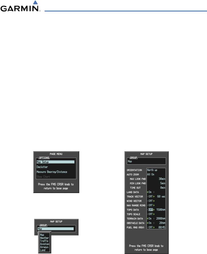
Customizing terrain and obstacle display on the Navigation Map Page:
1)Select the Navigation Map Page.
2)Press the MENU Key.
3)With ‘Map Setup’ highlighted, press the ENT Key (Figure 6-45).
4)Turn the small FMS Knob to select the ‘Map’ Group and press the ENT Key (Figure 6-46).
5)Turn the large FMS Knob or press the ENT Key to scroll though product selections (Figure 6-47).
•TERRAIN DATA – Turns the display of terrain data on or off and sets maximum range at which terrain is shown
•OBSTACLE DATA – Turns the display of obstacle data on or off and sets maximum range at which obstacles are shown
6)Turn the small FMS Knob to scroll though options for each product (ON/OFF, range settings).
7)Press the ENT Key to select an option.
8)Press the FMS Knob or CLR Key to return to the Navigation Map Page with the changed settings.
Figure 6-45 Navigation Map Page Menu
Figure 6-46 Navigation Map Page Setup Menu |
Figure 6-47 Navigation Map Page Setup Menu, Map Group |
190-00498-03 Rev.A |
Garmin G1000 Pilot’s Guide for Cessna Nav III |
6-33 |
HAZARD AVOIDANCE
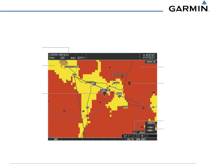
Additional information about obstacles can be displayed by panning over the display on the map. The map panning feature is enabled by pressing the RANGE Knob. The map range is adjusted by turning the RANGE Knob. If the map range is adjusted while panning is enabled, the map is re-centered on the Map Pointer.
Additional Information on Obstacle Selected with Map Pointer
Yellow Terrain Area (Between 100’ and 1000’ Below Aircraft Altitude)
Lighted Obstacle Selected
with Map Pointer
Red Terrain Area (Above or Within 100’ Below Aircraft Altitude)
Red Lighted Obstacles (Above or Within 100’ Below Aircraft Altitude)
Terrain Display Enabled
Terrain Legend
Figure 6-48 Terrain Information on the Navigation Map Page
TERRAIN PROXIMITY PAGE
The Terrain Proximity Page is specialized to show terrain and obstacle data in relation to the aircraft’s current altitude,withoutclutterfrom the basemap. Aviationdata (airports,VORs,and other NAVAIDs) can be displayed for reference.
Aircraft orientation on this map is always heading up unless there is no valid heading. Two views are available relative to the position of the aircraft: the 360° default display and the radar-like ARC (120°) display. Map range is adjustable with the RANGE Knob from 1 to 200 nm, as indicated by the map range rings (or arcs).
Displaying the Terrain Proximity Page:
1)Turn the large FMS Knob to select the Map Page Group.
2)Turn the small FMS Knob to select the Terrain Proximity Page.
3)To change the view,
a)Press the VIEW Softkey.
b)Press the 360 or ARC Softkey to select the desired view.
Or:
a) Press the MENU Key.
6-34 |
Garmin G1000 Pilot’s Guide for Cessna Nav III |
190-00498-03 Rev.A |
HAZARD AVOIDANCE
b) Select ‘View 120º’ or ‘View 360º’ (choice dependent on current state) and press the ENT Key to change the view.
Showing/hiding aviation information on the Terrain Proximity Page:
1)Press the MENU Key.
2)Select ‘Show Aviation Data’ or ‘Hide Aviation Data’ (choice dependent on current state) and press the ENT Key.
Black Terrain (More than 1000’ Below the Aircraft Altitude)
Yellow Terrain (Between 100’ and 1000’ Below the Aircraft Altitude)
Red Terrain (Above or Within 100’ Below the Aircraft Altitude)
Map Orientation
Current Aircraft GPSderived MSL Altitude
Map Range Rings
Terrain Legend
Yellow Terrain (Between 100’ and 1000’ Below the Aircraft Altitude)
Red Terrain (Above or Within 100’ Below the Aircraft Altitude)
Figure 6-49 Terrain Proximity Page
Map Range Arcs
Black Terrain
(Terrain More than 1000’ Below the Aircraft Altitude)
Terrain Legend
Figure 6-50 Terrain Proximity Page (ARC View)
190-00498-03 Rev.A |
Garmin G1000 Pilot’s Guide for Cessna Nav III |
6-35 |