

FLIGHT MANAGEMENT
4)Turn the small FMS Knob to display and scroll through the data options list.
5)Select the desired data.
6)Press the ENT Key. Pressing the DFLTS Softkey returns any field to its default setting.
5.2USING MAP DISPLAYS
Map displays are used extensively in the G1000 to provide situational awareness in flight. Most G1000 maps can display the following information:
•Airports, NAVAIDs, airspaces, airways, land data (highways, cities, lakes, rivers, borders, etc.) with names
•Map Pointer information (distance and bearing to pointer,locationofpointer,name,andotherpertinent information)
•Map range
•Wind direction and speed
•Map orientation
•Icons for enabled map features
•Aircraft icon (representing present position)
•Nav range ring
•Flight plan legs
•User waypoints
•Track vector
•Topography scale
•Topography data
The information in this section applies to the following maps unless otherwise noted:
• All Map Group Pages (MAP) |
• Flight Plan Pages (FPL) |
• All Waypoint Group Pages (WPT) |
• Direct-to Window |
• AUX - Trip Planning |
• PFD Inset Map |
• All Nearest Group Pages (NRST) |
• Procedure Loading Pages |
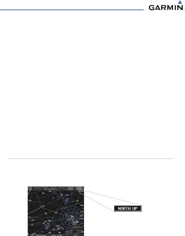
MAP ORIENTATION
Maps are shown in one of four different orientation options, allowing flexibility in determining aircraft position relative to other items on the map (north up) or for determining where map items are relative to where the aircraft is going (track up, desired track up, or heading up). The map orientation is shown in the upper right corner of the map.
Figure 5-3 Map Orientation
5-4 |
Garmin G1000 Pilot’s Guide for Cessna Nav III |
190-00498-03 Rev.A |
FLIGHT MANAGEMENT
•North up (NORTH UP) aligns the top of the map display to north (default setting).
•Track up (TRK UP) aligns the top of the map display to the current ground track.
•Desired track up (DTK UP) aligns the top of the map display to the desired course.
•Heading up (HDG UP) aligns the top of the map display to the current aircraft heading.
 NOTE: When panning or reviewing active flight plan legs in a non-North Up orientation, the map does not show the map orientation nor the wind direction and speed.
 NOTE: Map orientation can only be changed on the Navigation Map Page. Any other displays that show navigation data reflect the orientation selected for the Navigation Map Page:
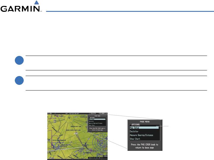
Changing the Navigation Map orientation:
1) With the Navigation Map Page displayed, press the MENU Key. The cursor flashes on the ‘Map Setup’ option.
Map Setup
Selection
Figure 5-4 Navigation Map Page Menu Window
2)Press the ENT Key to display the Map Setup Window.
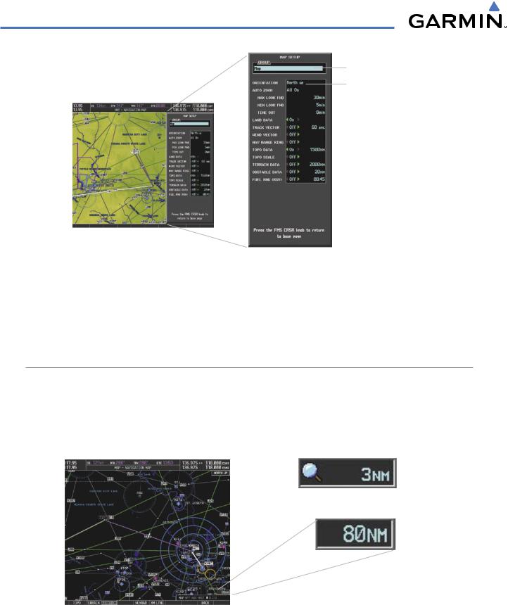
3)Turn the large FMS Knob, or press the ENT Key once, to select the ‘ORIENTATION’ field.
190-00498-03 Rev.A |
Garmin G1000 Pilot’s Guide for Cessna Nav III |
5-5 |
FLIGHT MANAGEMENT
Map Group Selection
Orientation Field
Figure 5-5 Map Setup Menu Window - Map Group
4)Turn the small FMS Knob to select the desired orientation.
5)Press the ENT Key to select the new orientation.
6)Press the FMS Knob to return to the base page.
MAP RANGE
There are 28 different map ranges available, from 500 feet to 2000 nm. The current range is indicated in the lower right corner of the map and represents the top-to-bottom distance covered by the map. When the map range is decreased to a point that exceeds the capability of the G1000 to accurately represent the map, a magnifying glass icon is shown to the left of the map range. To change the map range turn the Joystick counter-clockwise to decrease the range, or clockwise to increase the range.
Range Overzoom
Figure 5-6 Map Range
5-6 |
Garmin G1000 Pilot’s Guide for Cessna Nav III |
190-00498-03 Rev.A |

FLIGHT MANAGEMENT
AUTO ZOOM
Auto zoom allows the G1000 to change the map display range to the smallest range clearly showing the active waypoint. Auto zoom can be overridden by adjusting the range with the Joystick, and remains until the active waypoint changes, a terrain or traffic alert occurs, the aircraft takes off, or the manual override times out (timer set on Map Setup Window).
If a terrain caution or warning occurs, any map page displaying TAWS/TERRAIN data automatically adjusts to the smallest map range clearly showing the highest priority alert. If a new traffic advisory alert occurs, any map page capable of displaying traffic advisory alerts automatically adjusts to the smallest map range clearly showing the traffic advisory. When terrain or traffic alerts clear, the map returns to the previous auto zoom range based on the active waypoint.
The auto zoom function can be turned on or off independently for the PFD and MFD. Control of the ranges at which the auto zoom occurs is done by setting the minimum and maximum ‘look forward’ times (set on the Map Setup Window for the Map Group). These settings determine the minimum and maximum distance to display based upon the aircraft’s ground speed.
•Waypoints that are long distances apart cause the map range to increase to a point where many details on the map are decluttered. If this is not acceptable, lower the maximum look ahead time to a value that limits the auto zoom to an acceptable range.
•Waypoints that are very short distances apart cause the map range to decrease to a point where situational awareness may not be what is desired. Increase the minimum look ahead time to a value that limits the auto zoom to a minimum range that provides acceptable situational awareness.
•Flight plans that have a combination of long and short legs cause the range to increase and decrease as waypoints sequence. To avoid this, auto zoom can be disabled or the maximum/minimum times can be adjusted.
•The ‘time out’ time (configurable on the Map Setup Page for the Map Group) determines how long auto zoom is overridden by a manual adjustment of the range knob. At this expiration of this time, the auto zoom range is restored. Setting the ‘time out’ value to zero causes the manual override to never time out.
•Whenthemaximum‘lookforward’timeissettozero,theupperlimitbecomesthemaximumrangeavailable (2000 nm).
•When the minimum ‘look forward’ time is set to zero, the lower limit becomes 1.5 nm.
190-00498-03 Rev.A |
Garmin G1000 Pilot’s Guide for Cessna Nav III |
5-7 |
FLIGHT MANAGEMENT
Auto Zoom: |
|
|
|
|
Maximum Look Forward Time |
|
|
|
|
||
Off, MFD Only, PFD Only, All On |
|
|
|
|
|
|
|
|
|
||
|
|
|
|
Minimum Look Forward Time |
|
Manual Range Override |
|
|
|
|
|
|
|
|
|
||
|
|
|
|
|
|
Expiration Time |
|
|
|
|
|
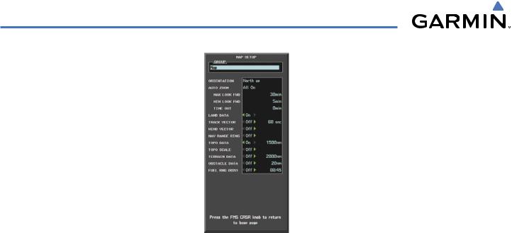
Figure 5-7 Map Setup Menu Window - Map Group,Auto Zoom
Configuring automatic zoom:
1)Press the MENU Key with the Navigation Map Page displayed. The cursor flashes on the ‘Map Setup’ option.
2)Press the ENT Key. The Map Setup Menu is displayed.
3)Select the ‘Map’ group.
4)Press the ENT Key.
5)Highlight the ‘AUTO ZOOM’ field.
6)Select ‘Off’,‘MFD Only’,‘PFD Only’, or ‘ALL On’.
7)Press the ENT Key to accept the selected option. The flashing cursor highlights the ‘MAX LOOK FWD’ field. Times are from zero to 999 minutes.
8)Use the FMS Knobs to set the time. Press the ENT Key.
9)Repeat step 8 for ‘MIN LOOK FWD’ (zero-99 minutes) and ‘MAX LOOK FWD’ (zero to 999 minutes).
10)Press the FMS Knob to return to the Navigation Map Page.
5-8 |
Garmin G1000 Pilot’s Guide for Cessna Nav III |
190-00498-03 Rev.A |