

- •Section 1 System Overview
- •1.1 System Description
- •1.2 Line Replaceable Units (LRU)
- •1.3 G1000 Controls
- •PFD/MFD Controls
- •Audio Panel Controls
- •1.4 Secure Digital (SD) Cards
- •1.5 System Power-up
- •1.6 System Operation
- •Normal Display Operation
- •Reversionary Display Operation
- •AHRS Operation
- •G1000 System Annunciations
- •Softkey Function
- •GPS Receiver Operation
- •1.7 Accessing G1000 Functionality
- •Menus
- •MFD Page Groups
- •MFD System Pages
- •1.8 Display Backlighting
- •Automatic Adjustment
- •Manual Adjustment
- •Section 2 Flight Instruments
- •2.1 Flight Instruments
- •Airspeed Indicator
- •Attitude Indicator
- •Altimeter
- •Vertical Speed Indicator (VSI)
- •Vertical Deviation
- •Horizontal Situation Indicator (HSI)
- •Course Deviation Indicator (CDI)
- •2.2 Supplemental Flight Data
- •Outside Air Temperature
- •Wind Data
- •Vertical Navigation (VNV) Indications
- •2.3 PFD Annunciations and Alerting Functions
- •G1000 System Alerting
- •Marker Beacon Annunciations
- •Traffic Annunciation
- •TAWS Annunciations
- •Altitude Alerting
- •Low Altitude Annunciation
- •Minimum Descent Altitude/Decision Height Alerting
- •2.4 Abnormal Operations
- •Abnormal GPS Conditions
- •Unusual Attitudes
- •Section 3 Engine Indication System (EIS)
- •3.1 Engine Display
- •3.2 Lean Display
- •Normally-aspirated Aircraft
- •Turbocharged Aircraft
- •3.3 System Display
- •Section 4 audio panel and CNS
- •4.1 Overview
- •MFD/PFD Controls and Frequency Display
- •Audio Panel Controls
- •4.2 COM Operation
- •COM Transceiver Selection and Activation
- •COM Transceiver Manual Tuning
- •Quick-Tuning and Activating 121.500 MHz
- •Auto-tuning the COM Frequency
- •Frequency Spacing
- •Automatic Squelch
- •Volume
- •4.3 NAV Operation
- •NAV Radio Selection and Activation
- •NAV Receiver Manual Tuning
- •Auto-tuning a NAV Frequency from the MFD
- •Marker Beacon Receiver
- •DME Tuning (Optional)
- •4.4 GTX 33 Mode S Transponder
- •Transponder Controls
- •Transponder Mode Selection
- •Entering a Transponder Code
- •IDENT Function
- •Flight ID Reporting
- •4.5 Additional Audio Panel Functions
- •Power-Up
- •Mono/Stereo Headsets
- •Speaker
- •Intercom
- •Passenger Address (PA) System
- •Clearance Recorder and Player
- •Entertainment Inputs
- •4.6 Audio Panel Preflight Procedure
- •4.7 Abnormal Operation
- •Stuck Microphone
- •COM Tuning Failure
- •Audio Panel Fail-Safe Operation
- •Reversionary Mode
- •Section 5 Flight Management
- •5.1 Introduction
- •Navigation Status Box
- •5.2 Using Map Displays
- •Map Orientation
- •Map Range
- •Map Panning
- •Measuring Bearing and Distance
- •Topography
- •Map Symbols
- •Airways
- •Track Vector
- •Wind Vector
- •Nav Range Ring
- •Fuel Range Ring
- •5.3 Waypoints
- •Airports
- •Intersections
- •NDBs
- •VORs
- •User Waypoints
- •5.4 Airspaces
- •5.5 Direct-to-Navigation
- •5.6 Flight Planning
- •Flight Plan Creation
- •Adding Waypoints To An Existing Flight Plan
- •Adding Airways to a Flight Plan
- •Adding Procedures To A Stored Flight Plan
- •Flight Plan Storage
- •Flight Plan Editing
- •Along Track Offsets
- •Parallel Track
- •Activating a Flight Plan Leg
- •Inverting a Flight Plan
- •Flight Plan Views
- •Closest Point of FPL
- •5.7 Vertical Navigation
- •Altitude Constraints
- •5.8 Procedures
- •Departures
- •Arrivals
- •Approaches
- •5.9 Trip Planning
- •Trip Planning
- •5.10 RAIM Prediction
- •5.11 Navigating a Flight Plan
- •5.12 Abnormal Operation
- •Section 6 Hazard Avoidance
- •6.1 XM Satellite Weather
- •Activating Services
- •Using XM Satellite Weather Products
- •6.2 WX-500 Stormscope (Optional)
- •Setting Up Stormscope on the Navigation Map
- •Selecting the Stormscope Page
- •6.3 Terrain Proximity
- •Displaying Terrain Proximity Data
- •Terrain Proximity Page
- •6.4 TAWs (Optional)
- •Displaying TAWS Data
- •TAWS Page
- •TAWS Alerts
- •System Status
- •6.5 Traffic Information Service (TIS)
- •Displaying TRAFFIC Data
- •Traffic Map Page
- •TIS Alerts
- •System Status
- •6.6 Traffic Advisory System (TAS) (Optional)
- •TAS Symbology
- •Operation
- •Altitude Display
- •Traffic Map Page Display Range
- •TAS Alerts
- •System Status
- •6.7 ADS-B Traffic (Optional)
- •Section 7 Automatic Flight Control System
- •7.2 Flight Director Operation
- •Activating the Flight Director
- •AFCS Status Box
- •Command Bars
- •Flight Director Modes
- •7.3 Vertical Modes
- •Pitch Hold Mode (PIT)
- •Selected Altitude capture Mode (ALTs)
- •Altitude hold mode (alt)
- •Vertical Speed Mode (VS)
- •Flight Level Change Mode (FLC)
- •Vertical Navigation Modes (VPTH, ALTV)
- •Glidepath Mode (GP) (waas only)
- •Glideslope Mode (GS)
- •Go Around (GA) Mode
- •7.4 Lateral Modes
- •Roll Hold Mode (ROL)
- •Heading Select Mode (HDG)
- •Navigation mode (GPS, VOR, LOC)
- •Approach mode (GPS, VAPP, LOC)
- •Backcourse Mode (BC)
- •7.5 Autopilot Operation
- •Engaging the Autopilot
- •Control Wheel Steering
- •Disengaging the Autopilot
- •7.6 Example Procedures
- •Departure
- •Intercepting a VOR Radial
- •Flying a Flight Plan/GPS Course
- •Descent
- •Approach
- •Go Around/Missed Approach
- •7.7 AFCS Annunciations and Alerts
- •AFCS Status Alerts
- •Overspeed Protection
- •Section 8 Additional Features
- •8.1 SafeTaxi
- •SafeTaxi Cycle Number and Revision
- •8.2 ChartView
- •ChartView Softkeys
- •Terminal Procedures Charts
- •Chart Options
- •Day/Night View
- •ChartView Cycle Number and Expiration Date
- •8.3 FliteCharts
- •FliteCharts Softkeys
- •Terminal Procedures Charts
- •Chart Options
- •Day/Night View
- •FliteCharts Cycle Number and Expiration Date
- •8.4 XM Radio Entertainment (Optional)
- •Activating XM Satellite Radio Services
- •Using XM Radio
- •Automatic Audio Muting
- •8.5 Scheduler
- •8.5 Abnormal Operation
- •Annunciations and Alerts
- •Alert Level Definitions
- •Nav III Aircraft Alerts
- •CO Guardian Messages
- •G1000 System Annunciations
- •Other G1000 Aural Alerts
- •G1000 System Message Advisories
- •AFCS Alerts
- •TAWS ALERTS
- •TAWS System Status Annunciations
- •SD Card Use
- •Jeppesen Databases
- •Garmin Databases
- •Glossary
- •Frequently Asked Questions
- •General TIS Information
- •Introduction
- •TIS vs. TAS/TCAS
- •TIS Limitations
- •Map Symbols
- •Index
AUTOMATIC FLIGHT CONTROL SYSTEM
7.3 VERTICAL MODES
Table 7-2 lists the vertical modes with their corresponding controls and annunciations. The mode reference is displayed next to the active mode annunciation for Altitude Hold, Vertical Speed, and Flight Level Change modes. The NOSE UP/NOSE DN Keys can be used to change the vertical mode reference while operating under Pitch Hold, Vertical Speed, or Flight Level Change Mode. Increments of change and acceptable ranges of values for each of these references using the NOSE UP/NOSE DN Keys are also listed in the table.
Vertical Mode |
Description |
Control |
Annunciation |
Reference |
Reference |
||
Range |
Change |
||||||
|
|
|
|
|
|
Increment |
|
|
|
|
|
|
|
|
|
|
Holds aircraft pitch attitude; may |
|
|
|
|
|
|
Pitch Hold |
be used to climb/descend to the |
(default) |
|
|
PIT |
-15° to +20° |
0.5° |
|
Selected Altitude |
|
|
|
|
|
|
Selected Altitude Capture |
Captures the Selected Altitude |
* |
|
ALTS |
|
|
|
Altitude Hold |
Holds current Altitude Reference |
ALT Key |
ALT |
|
nnnnn FT |
|
|
|
Holds aircraft vertical speed; may |
|
|
|
|
-2000 to |
|
Vertical Speed |
be used to climb/descend to the |
VS Key |
VS |
|
nnnn FPM |
100 fpm |
|
|
+1500 fpm |
||||||
|
Selected Altitude |
|
|
|
|
|
|
|
Holds aircraft airspeed while |
|
|
|
|
80 to 200 kts |
|
|
|
|
|
|
(350) |
|
|
Flight Level Change |
aircraft is climbing/descending to |
FLC Key |
FLC |
|
nnn KT |
1 kt |
|
|
80 to 210 kts |
||||||
|
the Selected Altitude |
|
|
|
|
(400) |
|
|
|
|
|
|
|
|
|
Vertical Path Tracking |
Captures and tracks descent legs |
VNV |
|
VPTH |
|
|
|
of an active vertical profile |
Key |
|
|
|
|||
|
|
|
|
|
|
||
VNV Target Altitude Capture |
Captures the Vertical Navigation |
** |
|
ALTV |
|
|
|
(VNV) Target Altitude |
|
|
|
||||
|
|
|
|
|
|
|
|
Glidepath*** |
Captures and tracks the WAAS |
|
|
|
GP |
|
|
glidepath on approach |
APR |
|
|
|
|
||
|
|
|
|
|
|
||
Glideslope |
Captures and tracks the ILS |
Key |
|
|
GS |
|
|
glideslope on approach |
|
|
|
|
|
||
|
|
|
|
|
|
|
|
|
Disengages the autopilot and |
GA |
|
|
|
|
|
Go Around |
commands a constant pitch angle |
|
|
GA |
7° |
|
|
Switch |
|
|
|
||||
|
and wings level |
|
|
|
|
|
|
*ALTS is armed automatically when PIT, VS, FLC, or GA is active, and under VPTH when the Selected Altitude is to be captured instead of the VNV Target Altitude.
** ALTV is armed automatically under VPTH when the VNV Target Altitude is to be captured instead of the Selected Altitude.
***GP is available in installations with GIA 63W IAUs when WAAS is available.
Table 7-2 Flight Director Vertical Modes
190-00498-03 Rev.A |
Garmin G1000 Pilot’s Guide for Cessna Nav III |
7-7 |
AUTOMATIC FLIGHT CONTROL SYSTEM
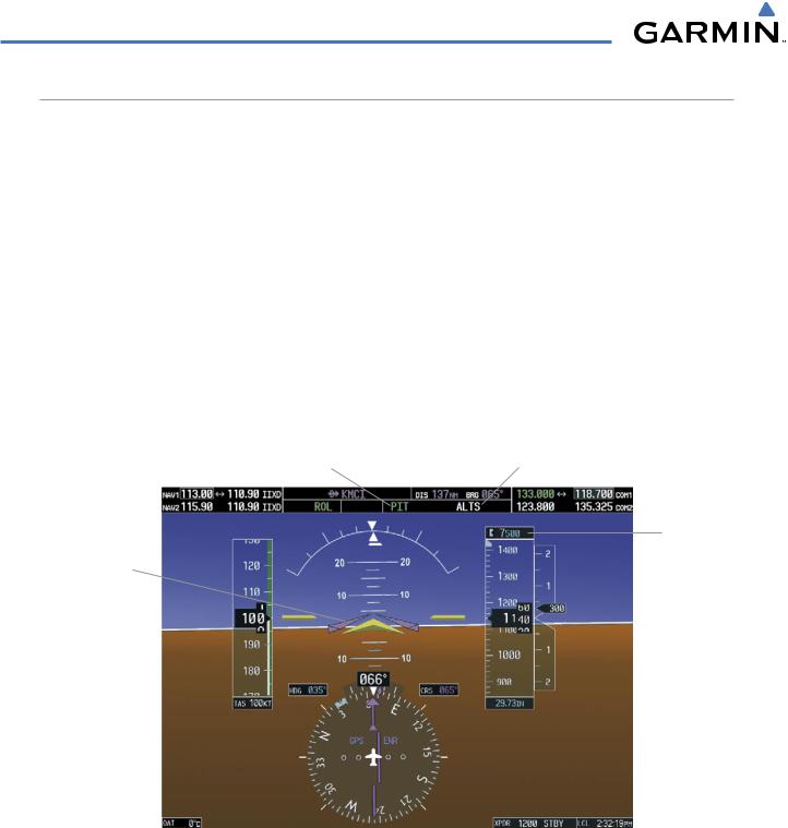
PITCH HOLD MODE (PIT)
When the flight director is activated (the FD Key is pressed), Pitch Hold Mode is selected by default. Pitch Hold Mode is indicated as the active pitch mode by the green annunciation ‘PIT’. This mode may be used for climb or descent to the Selected Altitude (shown above the Altimeter), since Selected Altitude Capture Mode is automatically armed when Pitch Hold Mode is activated.
In Pitch Hold Mode, the flight director maintains a constant pitch attitude, the pitch reference. The pitch reference is set to the aircraft pitch attitude at the moment of mode selection. If the aircraft pitch attitude exceeds the flight director pitch command limitations, the flight director commands a pitch angle equal to the nose-up/down limit.
CHANGING THE PITCH REFERENCE
When operating in Pitch Hold Mode, the pitch reference can be adjusted by:
•Using the NOSE UP/NOSE DN Keys
•By pressing the CWS Button, hand-flying the aircraft to establish a new pitch reference, then releasing the
CWS Button
Pitch Hold |
Selected Altitude |
Mode Active |
Capture Mode Armed |
Selected
Altitude
Command Bars
Maintain
Desired Pitch
Reference
Figure 7-5 Pitch Hold Mode
7-8 |
Garmin G1000 Pilot’s Guide for Cessna Nav III |
190-00498-03 Rev.A |

AUTOMATIC FLIGHT CONTROL SYSTEM
SELECTED ALTITUDE CAPTURE MODE (ALTS)
Selected Altitude Capture Mode is automatically armed with activation of the following modes:
• Pitch Hold |
• Go Around |
• Vertical Speed |
• Vertical Path Tracking (if the Selected Altitude is to |
• Flight Level Change |
be captured instead of the VNV Target Altitude) |
|
Thewhite‘ALTS’annunciationindicatesSelectedAltitudeCaptureModeisarmed(seeFigure7-5forexample). The ALT Knob is used to set the Selected Altitude (shown above the Altimeter) until Selected Altitude Capture Mode becomes active.
As the aircraft nears the Selected Altitude, the flight director automatically transitions to Selected Altitude Capture Mode with Altitude Hold Mode armed (Figure 7-6). This automatic transition is indicated by the green ‘ALTS’ annunciation flashing for up to 10 seconds and the appearance of the white ‘ALT” annunciation. The Selected Altitude is shown as the Altitude Reference beside the ‘ALTS’ annunciation.
At 50 feet from the Selected Altitude, the flight director automatically transitions from Selected Altitude Capture to Altitude Hold Mode and holds the Selected Altitude (shown as the Altitude Reference). As Altitude Hold Mode becomes active, the white ‘ALT’ annunciation moves to the active pitch mode field and flashes green for 10 seconds to indicate the automatic transition.
Altitude Reference (in this case, equal to Selected Altitude)
Flash up to 10 sec, Indicating Automatic Transition
Figure 7-6 Automatic Mode Transitions During Altitude Capture
CHANGING THE SELECTED ALTITUDE
 NOTE: Pressing the CWS Button while in Selected Altitude Capture Mode does not cancel the mode.
Use of the ALT Knob to change the Selected Altitude while Selected Altitude Capture Mode is active causes the flight director to revert to Pitch Hold Mode with Selected Altitude Capture Mode armed for the new Selected Altitude.
190-00498-03 Rev.A |
Garmin G1000 Pilot’s Guide for Cessna Nav III |
7-9 |

AUTOMATIC FLIGHT CONTROL SYSTEM
ALTITUDE HOLD MODE (ALT)
Altitude Hold Mode can be activated by pressing the ALTKey; the flight director maintains the current aircraft altitude (to the nearest 10 feet) as the Altitude Reference. The flight director’s Altitude Reference, shown in the AFCS Status Box, is independent of the Selected Altitude, displayed above the Altimeter. Altitude Hold Mode active is indicated by a green ‘ALT’ annunciation in the AFCS Status Box.
Altitude Hold Mode is automatically armed when the flight director is in Selected Altitude Capture Mode (see Figure 7-6). Selected Altitude Capture Mode automatically transitions to Altitude Hold Mode when the altitude error is less than 50 feet. In this case, the Selected Altitude becomes the flight director’s Altitude Reference.
CHANGING THE ALTITUDE REFERENCE
 NOTE: Turning the ALT Knob while in Altitude Hold Mode changes the Selected Altitude, but not the flight director’s Altitude Reference, and does not cancel the mode.
With the CWS Button depressed, the aircraft can be hand-flown to a new Altitude Reference. When the CWS Button is released at the desired altitude, the new altitude is established as the Altitude Reference.
Altitude Hold |
Altitude |
Mode Active |
Reference |
Selected
Altitude
Selected
Altitude
Bug
Command Bars
Hold Pitch Attitude to Maintain Altitude Reference
Figure 7-7 Altitude Hold Mode
7-10 |
Garmin G1000 Pilot’s Guide for Cessna Nav III |
190-00498-03 Rev.A |