

- •Section 1 System Overview
- •1.1 System Description
- •1.2 Line Replaceable Units (LRU)
- •1.3 G1000 Controls
- •PFD/MFD Controls
- •Audio Panel Controls
- •1.4 Secure Digital (SD) Cards
- •1.5 System Power-up
- •1.6 System Operation
- •Normal Display Operation
- •Reversionary Display Operation
- •AHRS Operation
- •G1000 System Annunciations
- •Softkey Function
- •GPS Receiver Operation
- •1.7 Accessing G1000 Functionality
- •Menus
- •MFD Page Groups
- •MFD System Pages
- •1.8 Display Backlighting
- •Automatic Adjustment
- •Manual Adjustment
- •Section 2 Flight Instruments
- •2.1 Flight Instruments
- •Airspeed Indicator
- •Attitude Indicator
- •Altimeter
- •Vertical Speed Indicator (VSI)
- •Vertical Deviation
- •Horizontal Situation Indicator (HSI)
- •Course Deviation Indicator (CDI)
- •2.2 Supplemental Flight Data
- •Outside Air Temperature
- •Wind Data
- •Vertical Navigation (VNV) Indications
- •2.3 PFD Annunciations and Alerting Functions
- •G1000 System Alerting
- •Marker Beacon Annunciations
- •Traffic Annunciation
- •TAWS Annunciations
- •Altitude Alerting
- •Low Altitude Annunciation
- •Minimum Descent Altitude/Decision Height Alerting
- •2.4 Abnormal Operations
- •Abnormal GPS Conditions
- •Unusual Attitudes
- •Section 3 Engine Indication System (EIS)
- •3.1 Engine Display
- •3.2 Lean Display
- •Normally-aspirated Aircraft
- •Turbocharged Aircraft
- •3.3 System Display
- •Section 4 audio panel and CNS
- •4.1 Overview
- •MFD/PFD Controls and Frequency Display
- •Audio Panel Controls
- •4.2 COM Operation
- •COM Transceiver Selection and Activation
- •COM Transceiver Manual Tuning
- •Quick-Tuning and Activating 121.500 MHz
- •Auto-tuning the COM Frequency
- •Frequency Spacing
- •Automatic Squelch
- •Volume
- •4.3 NAV Operation
- •NAV Radio Selection and Activation
- •NAV Receiver Manual Tuning
- •Auto-tuning a NAV Frequency from the MFD
- •Marker Beacon Receiver
- •DME Tuning (Optional)
- •4.4 GTX 33 Mode S Transponder
- •Transponder Controls
- •Transponder Mode Selection
- •Entering a Transponder Code
- •IDENT Function
- •Flight ID Reporting
- •4.5 Additional Audio Panel Functions
- •Power-Up
- •Mono/Stereo Headsets
- •Speaker
- •Intercom
- •Passenger Address (PA) System
- •Clearance Recorder and Player
- •Entertainment Inputs
- •4.6 Audio Panel Preflight Procedure
- •4.7 Abnormal Operation
- •Stuck Microphone
- •COM Tuning Failure
- •Audio Panel Fail-Safe Operation
- •Reversionary Mode
- •Section 5 Flight Management
- •5.1 Introduction
- •Navigation Status Box
- •5.2 Using Map Displays
- •Map Orientation
- •Map Range
- •Map Panning
- •Measuring Bearing and Distance
- •Topography
- •Map Symbols
- •Airways
- •Track Vector
- •Wind Vector
- •Nav Range Ring
- •Fuel Range Ring
- •5.3 Waypoints
- •Airports
- •Intersections
- •NDBs
- •VORs
- •User Waypoints
- •5.4 Airspaces
- •5.5 Direct-to-Navigation
- •5.6 Flight Planning
- •Flight Plan Creation
- •Adding Waypoints To An Existing Flight Plan
- •Adding Airways to a Flight Plan
- •Adding Procedures To A Stored Flight Plan
- •Flight Plan Storage
- •Flight Plan Editing
- •Along Track Offsets
- •Parallel Track
- •Activating a Flight Plan Leg
- •Inverting a Flight Plan
- •Flight Plan Views
- •Closest Point of FPL
- •5.7 Vertical Navigation
- •Altitude Constraints
- •5.8 Procedures
- •Departures
- •Arrivals
- •Approaches
- •5.9 Trip Planning
- •Trip Planning
- •5.10 RAIM Prediction
- •5.11 Navigating a Flight Plan
- •5.12 Abnormal Operation
- •Section 6 Hazard Avoidance
- •6.1 XM Satellite Weather
- •Activating Services
- •Using XM Satellite Weather Products
- •6.2 WX-500 Stormscope (Optional)
- •Setting Up Stormscope on the Navigation Map
- •Selecting the Stormscope Page
- •6.3 Terrain Proximity
- •Displaying Terrain Proximity Data
- •Terrain Proximity Page
- •6.4 TAWs (Optional)
- •Displaying TAWS Data
- •TAWS Page
- •TAWS Alerts
- •System Status
- •6.5 Traffic Information Service (TIS)
- •Displaying TRAFFIC Data
- •Traffic Map Page
- •TIS Alerts
- •System Status
- •6.6 Traffic Advisory System (TAS) (Optional)
- •TAS Symbology
- •Operation
- •Altitude Display
- •Traffic Map Page Display Range
- •TAS Alerts
- •System Status
- •6.7 ADS-B Traffic (Optional)
- •Section 7 Automatic Flight Control System
- •7.2 Flight Director Operation
- •Activating the Flight Director
- •AFCS Status Box
- •Command Bars
- •Flight Director Modes
- •7.3 Vertical Modes
- •Pitch Hold Mode (PIT)
- •Selected Altitude capture Mode (ALTs)
- •Altitude hold mode (alt)
- •Vertical Speed Mode (VS)
- •Flight Level Change Mode (FLC)
- •Vertical Navigation Modes (VPTH, ALTV)
- •Glidepath Mode (GP) (waas only)
- •Glideslope Mode (GS)
- •Go Around (GA) Mode
- •7.4 Lateral Modes
- •Roll Hold Mode (ROL)
- •Heading Select Mode (HDG)
- •Navigation mode (GPS, VOR, LOC)
- •Approach mode (GPS, VAPP, LOC)
- •Backcourse Mode (BC)
- •7.5 Autopilot Operation
- •Engaging the Autopilot
- •Control Wheel Steering
- •Disengaging the Autopilot
- •7.6 Example Procedures
- •Departure
- •Intercepting a VOR Radial
- •Flying a Flight Plan/GPS Course
- •Descent
- •Approach
- •Go Around/Missed Approach
- •7.7 AFCS Annunciations and Alerts
- •AFCS Status Alerts
- •Overspeed Protection
- •Section 8 Additional Features
- •8.1 SafeTaxi
- •SafeTaxi Cycle Number and Revision
- •8.2 ChartView
- •ChartView Softkeys
- •Terminal Procedures Charts
- •Chart Options
- •Day/Night View
- •ChartView Cycle Number and Expiration Date
- •8.3 FliteCharts
- •FliteCharts Softkeys
- •Terminal Procedures Charts
- •Chart Options
- •Day/Night View
- •FliteCharts Cycle Number and Expiration Date
- •8.4 XM Radio Entertainment (Optional)
- •Activating XM Satellite Radio Services
- •Using XM Radio
- •Automatic Audio Muting
- •8.5 Scheduler
- •8.5 Abnormal Operation
- •Annunciations and Alerts
- •Alert Level Definitions
- •Nav III Aircraft Alerts
- •CO Guardian Messages
- •G1000 System Annunciations
- •Other G1000 Aural Alerts
- •G1000 System Message Advisories
- •AFCS Alerts
- •TAWS ALERTS
- •TAWS System Status Annunciations
- •SD Card Use
- •Jeppesen Databases
- •Garmin Databases
- •Glossary
- •Frequently Asked Questions
- •General TIS Information
- •Introduction
- •TIS vs. TAS/TCAS
- •TIS Limitations
- •Map Symbols
- •Index
ADDITIONAL FEATURES
SECTION 8 ADDITIONAL FEATURES
 NOTE: The availability of SafeTaxi, ChartView, or FliteCharts in electronic form may not preclude the requirement to carry paper charts aboard the aircraft. See AC 120-76A for more information.
Additional features of the G1000 include the following:
•SafeTaxi™ diagrams
•ChartView and FliteCharts™ electronic charts
•XM Radio entertainment
•Scheduler
SafeTaxi diagrams provide detailed taxiway, runway, and ramp information at more than 700 airports in the United States. By decreasing range on an airport that has a SafeTaxi diagram available, a close up view of the airport layout can be seen.
The optional ChartView and FliteCharts provide on-board electronic terminal procedures charts. Electronic charts offer the convenience of rapid access to essential information. Either ChartView or FliteCharts may be configured in the system, but not both.
The optional XM Radio entertainment audio feature of the GDL 69A Data Link Receiver handles more than 170 channels of music, news, and sports. XM Radio offers more entertainment choices and longer range coverage than commercial broadcast stations.
The Scheduler feature can be used to enter and display short term or long term reminder messages such as Switch fuel tanks, Change oil, or Altimeter-Transponder Check in the Alerts Window on the PFD.
8.1 SAFETAXI
SafeTaxiisanenhancedfeaturethatgivesgreatermapdetailwhenviewingairportsatcloserange. Themaximum map ranges for enhanced detail are pilot configurable. When viewing at ranges close enough to show the airport detail, the map reveals taxiways with identifying letters/numbers, airport Hot Spots, and airport landmarks including ramps, buildings, control towers, and other prominent features. Resolution is greater at lower map ranges. When the aircraft location is within the screen boundary, including within SafeTaxi ranges, an airplane symbol is shown on any of the navigation map views for enhanced position awareness.
Designated Hot Spots are recognized at airports with many intersecting taxiways and runways, and/or complex ramp areas. Airport Hot Spots are outlined to caution pilots of areas on an airport surface where positional awareness confusion or runway incursions happen most often. Hot Spots are defined with a magenta circle or outline around the region of possible confusion.
190-00498-03 Rev A |
Garmin G1000 Pilot’s Guide for Cessna Nav III |
8-1 |

ADDITIONAL FEATURES
Any map page that displays the navigation view can also show the SafeTaxi airport layout within the maximum configured range. The following is a list of pages where the SafeTaxi feature can be seen:
• Navigation Map Page |
• VOR Information Page |
• Inset Map (PFD) |
• User Waypoint Information Page |
• Weather Datalink Page |
• Trip Planning Page |
• Airport Information Page |
• Nearest Pages |
• Intersection Information Page |
• Active and Stored Flight Plan Pages |
• NDB Information Page |
|
During ground operations the aircraft’s position is displayed in reference to taxiways, runways, and airport features. In the example shown, the aircraft is on taxiway Bravo approaching the High Alert Intersection boundary on KSFO airport. Airport Hot Spots are outlined in magenta. When panning over the airport, features such as runway holding lines and taxiways are shown at the cursor.
Aircraft
Position
Taxiway
Identification
Airport Hot
Spot Outline
Airport
Features
DCLTR Softkey
Removes Taxiway Markings
Figure 8-1 SafeTaxi Depiction on the Navigation Map Page (Cessna 182 MFD Shown)
The DCLTR Softkey (declutter) label advances to DCLTR-1, DCLTR -2, and DCLTR-3 each time the softkey is pressed for easy recognition of decluttering level. Pressing the DCLTRSoftkey removes the taxiway markings and airport feature labels. Pressing the DCLTR-1 Softkey removes VOR station ID, the VOR symbol, and intersection names if within the airport plan view. Pressing the DCLTR-2 Softkey removes the airport runway layout, unless the airport in view is part of an active route structure. Pressing the DCLTR-3 Softkey cycles back to the original map detail. Refer to Map Declutter Levels in the Flight Management Section.
8-2 |
Garmin G1000 Pilot’s Guide for Cessna Nav III |
190-00498-03 Rev A |

ADDITIONAL FEATURES
Configuring SafeTaxi range:
1)While viewing the Navigation Map Page, press the MENU Key to display the PAGE MENU.
2)Turn the large FMS Knob to highlight the Map Setup Menu Option and press the ENT Key.
Figure 8-2 Navigation Map PAGE MENU, Map Setup Option
3)Turn the FMS Knob to select the Aviation Group and press the ENT Key.
4)Turn the large FMS Knob to scroll through the Aviation Group options to SAFETAXI.
5)Turn the small FMS Knob to display the range of distances.
6)Turn either FMS Knob to select the desired distance for maximum SafeTaxi display range.
7)Press the ENT Key to complete the selection.
8)Press the FMS Knob to return to the Navigation Map Page.
SAFETAXI
Option
SafeTaxi
Range
Options
Figure 8-3 MAP SETUP Menu,Aviation Group, SAFETAXI Range Options
190-00498-03 Rev A |
Garmin G1000 Pilot’s Guide for Cessna Nav III |
8-3 |
ADDITIONAL FEATURES
SAFETAXI CYCLE NUMBER AND REVISION
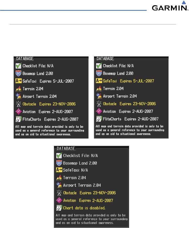
The SafeTaxi database is revised every 56 days. SafeTaxi is always available for use after the expiration date. When turning on the G1000, the Power-up Page indicates whether the databases are current, out of date, or not available. The Power-up Page shows the SafeTaxi database is current when the SafeTaxi Expires date is shown in white. When the SafeTaxi cycle has expired, the SafeTaxi Expires date appears in yellow. The message SafeTaxi: N/A appears in white if no SafeTaxi data is available on the database card.
SafeTaxi Database is Current |
SafeTaxi Database has Expired |
SafeTaxi Database Not Available
Figure 8-4 Power-up Page, SafeTaxi Database
8-4 |
Garmin G1000 Pilot’s Guide for Cessna Nav III |
190-00498-03 Rev A |
ADDITIONAL FEATURES
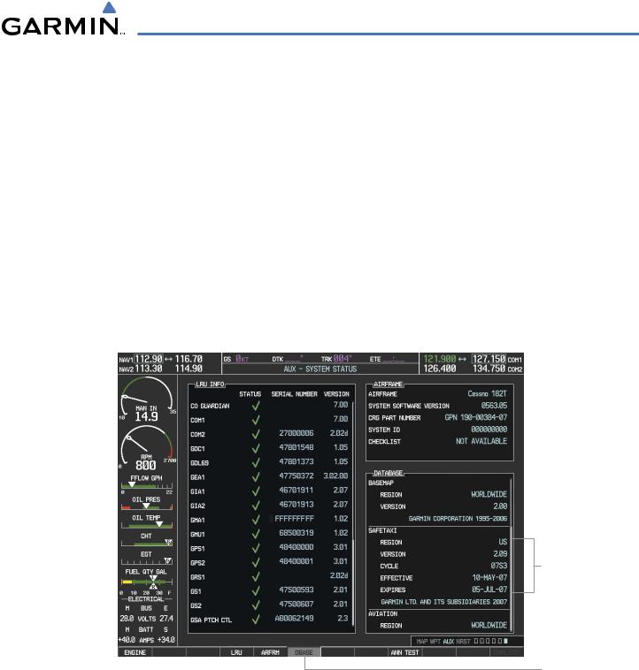
The SafeTaxi Region, Version, Cycle, Effective date and Expires date of the database cycle can also be found on the AUX - System Status page. SafeTaxi information appears in blue and yellow text. The EFFECTIVE date appears in blue when data is current and in yellow when the current date is before the effective date. The EXPIRES date appears in blue when data is current and in yellow when expired (Figures 8-5 and 8-6). SafeTaxi REGION NOT AVAILABLE appears in blue if SafeTaxi data is not available on the database card (Figure 8-6). Expired SafeTaxi data is never disabled.
Press the DBASE Softkey for scrolling through the database information. Scroll through the database with the FMS knob or ENT Key.
The SafeTaxi database cycle number shown in the figure, 07S3, is deciphered as follows: 07 – Indicates the year 2007
S – Indicates the data is for SafeTaxi
3 – Indicates the third issue of the SafeTaxi database for the year
The SafeTaxi EFFECTIVE date 10–MAY–07 is the beginning date for the current database cycle. SafeTaxi EXPIRES date 05–JUL–07 is the revision date for the next database cycle.
SafeTaxi Data
DBASE Softkey
Selected
Figure 8-5 AUX – System Status Page, SafeTaxi Current Information
The SafeTaxi database is provided by Garmin. Refer to Updating Garmin Databases in Appendix B for instructions on revising the SafeTaxi database.
190-00498-03 Rev A |
Garmin G1000 Pilot’s Guide for Cessna Nav III |
8-5 |
ADDITIONAL FEATURES
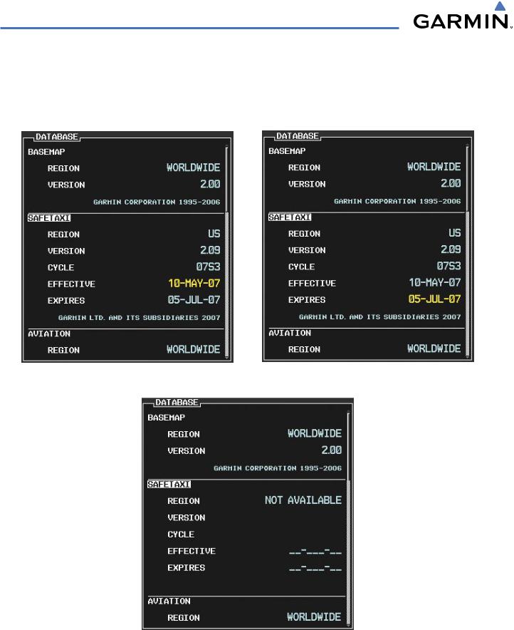
The other three possible AUX - System Status page conditions are shown here. The EFFECTIVE date is the beginning date for this database cycle. If the present date is before the effective date, the EFFECTIVE date appears in yellow and the EXPIRES date appears in blue. The EXPIRES date is the revision date for the next database cycle. NOT AVAILABLE indicates that SafeTaxi is not available on the database card or no database card is inserted.
Current Date is before Effective Date |
SafeTaxi Database has Expired |
SafeTaxi Database Not Installed
Figure 8-6 AUX – System Status Page, SafeTaxi Expired, SafeTaxi Not Available
8-6 |
Garmin G1000 Pilot’s Guide for Cessna Nav III |
190-00498-03 Rev A |