


FLIGHT MANAGEMENT
SECTION 5 FLIGHT MANAGEMENT
5.1 INTRODUCTION
The G1000 is an integrated flight, engine, communication, navigation and surveillance system. This section of the Pilot’s Guide explains flight management using the G1000.
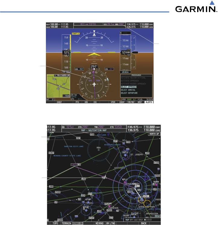
The most prominent part of the G1000 are the two full color displays: one Primary Flight Displays (PFD) and one Multi Function Display (MFD). The information to successfully navigate the aircraft using the GPS sensors is displayed on the PFD and the MFD. See examples in the Figure 5-1 and Figure 5-2. Detailed descriptions of GPS navigation functions are discussed later in this section.
A brief description of the GPS navigation data on the PFD and MFD follows.
Navigation mode indicates which sensor is providing the course data (e.g., GPS, VOR) and the flight plan phase (e.g., Departure (DPRT), Terminal (TERM), Enroute (ENR), Oceanic (OCN), Approach (LNAV, LNAV+V, L/VNAV, or LPV), or Missed Approach (MAPR)). L/VNAV and LPV approaches are only available with WAAS.
The Inset Map is a small version of the MFD Navigation Map and can be displayed in the lower left corner of the PFD. When the system is in reversionary mode, the Inset Map is displayed in the lower right corner. The Inset Map is displayed by pressing the INSET Softkey. Selecting the INSET Softkey again, then selecting the OFF Softkey removes the Inset Map.
The Navigation Map displays aviation data (e.g., airports, VORs, airways, airspaces), geographic data (e.g., cities, lake, highways, borders), topographic data (map shading indicating elevation), and hazard data (e.g., traffic, terrain, weather). The amount of displayed data can be reduced by selecting the DCLTR Softkey. The Navigation Map can be oriented four different ways: North Up (NORTH UP), Track Up (TRK UP), Desired Track Up (DTK UP), or Heading Up (HDG UP).
An aircraft icon is placed on the Navigation Map at the location corresponding to the calculated present position. The aircraft position and the flight plan legs are accurately based on GPS calculations. The basemap upon which these are placed are from a source with less resolution, therefore the relative position of the aircraft to map features is not exact. The leg of the active flight plan currently being flown is shown as a magenta line on the navigation map. The other legs are shown in white.
There are 28 different map ranges available, from 500 feet to 2000 nm. The current range is indicated in the lower right corner of the map and represents the top-to-bottom distance covered by the map. To change the map range on any map, turn the Joystick counter-clockwise to zoom in ( -, decreasing), or clockwise to zoom out (+, increasing).
The Direct-to Window, the Flight Plan Window, the Procedures Window, and the Nearest Airports Window can be displayed in the lower right corner of the PFD. Details of these windows are discussed in detail later in the section.
190-00498-03 Rev.A |
Garmin G1000 Pilot’s Guide for Cessna Nav III |
5-1 |
FLIGHT MANAGEMENT
Navigation Status Box
Navigation Mode |
|
|
|
|
|
|
|
|
|
|
|
|
|
||||
Inset Map |
|
|
|
|
|
|
|
|
|
|
|
|
Location of: |
||||
|
|
|
|
|
|
|
|
|
|
|
|
||||||
|
|
|
|
|
|
|
|
|
|
|
|
|
|||||
|
|
|
|
|
|
|
|
|
|
|
|
|
- Direct To Window |
||||
|
|
|
|
|
|
|
|
|
|
|
|
|
- Flight Plan Window |
||||
|
|
|
|
|
|
|
|
|
|
|
|
|
- Procedures Window |
||||
|
|
|
|
|
|
|
|
|
|
|
|
|
- Nearest Airports Window |
||||
|
|
|
|
|
Figure 5-1 GPS Navigation Information on the PFD |
||||||||||||
Navigation Status Box |
|
|
|
|
|
|
|
|
|
|
|
|
Map Orientation |
||||
|
|
|
|
|
|
|
|
|
|
|
|
||||||
Navigation Page Title |
|
|
|
|
|
|
|
|
|
|
|||||||
|
|
|
|
|
|
|
|
|
|
||||||||
|
|
|
|
|
|
|
|
|
|
|
|
|
|||||
Navigation Map |
|
|
|
|
|
|
|
|
|
|
|
|
|
|
|
||
|
|
|
|
|
|
|
|
|
|
|
|
|
|
|
|||
- Aviation Data |
|
|
|
|
|
|
|
|
|
|
|
|
|
||||
- Geographic Data |
|
|
|
|
|
|
|
|
|
|
|
|
|
||||
- Topographic Data |
|
|
|
|
|
|
|
|
|
|
|
|
|
||||
- Hazard Data |
|
|
|
|
|
|
|
|
|
|
|
|
|
||||
Aircraft Icon |
|
|
|
|
|
|
|
|
|
|
|
|
|
||||
at Present Position |
|
|
|
|
|
|
|
|
|
|
|
|
Active Flight Plan Leg |
||||
|
|
|
|
|
|
|
|
|
|
|
|
||||||
Flight Plan Leg |
|
|
|
|
|
|
|
|
|
|
|
|
Map Range |
||||
|
|
|
|
|
|
|
|
|
|
|
|
||||||
|
|
|
|
|
|
|
|
|
|
|
|
|
|
|
|
||
|
|
|
|
|
|
|
|
|
|
|
|
|
|
|
|
||
|
|
|
|
|
Figure 5-2 GPS Navigation Information on the MFD Navigation Page |
||||||||||||
5-2 |
Garmin G1000 Pilot’s Guide for Cessna Nav III |
190-00498-03 Rev.A |
FLIGHT MANAGEMENT
NAVIGATION STATUS BOX
The Navigation Status Box located at the top of the PFD contains two fields displaying the following information:
PFD Navigation Status Box
•Active flight plan leg (e.g., ‘D-> KICT’ or ‘KIXD - > KCOS’) or flight plan annunciations (e.g., ‘Turn right to 021˚ in 8 seconds’)
•Distance (DIS) and Bearing (BRG) to the next waypoint or flight plan annunciations (e.g., ‘TOD within 1 minute’)
The symbols used in the PFD status bar are:
Symbol Description
Active Leg
Direct-to
Right ProcedureTurn
Left ProcedureTurn
Right Holding Pattern
Left Holding Pattern
Vector to Final
Right DMEArc
Left DMEArc
The Navigation Status Box located at the top of the MFD contains four data fields, each displaying one of the following items:
•Bearing (BRG)
•Distance (DIS)
•Desired Track (DTK)
•Enroute Safe Altitude (ESA)
•Estimated Time of Arrival (ETA)
•Estimated Time Enroute (ETE)
•Ground Speed (GS)
•Minimum Safe Altitude (MSA)
•True Air Speed (TAS)
•Track Angle Error (TKE)
•Track (TRK)
•Vertical Speed Required (VSR)
•Crosstrack Error (XTK)
MFD Navigation Status Box
The navigation information displayed in the four data fields can be selected on the MFD Data Bar Fields Box on the AUX - System Setup Page. The default selections (in order left to right) are GS, DTK, TRK, and ETE.
Changing a field in the MFD Navigation Status Box:
1)Select the System Setup Page.
2)Press the FMS Knob momentarily to activate the flashing cursor.
3)Turn the large FMS Knob to highlight the desired field number in the MFD Data Bar Fields Box.
190-00498-03 Rev.A |
Garmin G1000 Pilot’s Guide for Cessna Nav III |
5-3 |