- •Section 1 System Overview
- •1.1 System Description
- •1.2 Line Replaceable Units (LRU)
- •1.3 G1000 Controls
- •PFD/MFD Controls
- •Audio Panel Controls
- •1.4 Secure Digital (SD) Cards
- •1.5 System Power-up
- •1.6 System Operation
- •Normal Display Operation
- •Reversionary Display Operation
- •AHRS Operation
- •G1000 System Annunciations
- •Softkey Function
- •GPS Receiver Operation
- •1.7 Accessing G1000 Functionality
- •Menus
- •MFD Page Groups
- •MFD System Pages
- •1.8 Display Backlighting
- •Automatic Adjustment
- •Manual Adjustment
- •Section 2 Flight Instruments
- •2.1 Flight Instruments
- •Airspeed Indicator
- •Attitude Indicator
- •Altimeter
- •Vertical Speed Indicator (VSI)
- •Vertical Deviation
- •Horizontal Situation Indicator (HSI)
- •Course Deviation Indicator (CDI)
- •2.2 Supplemental Flight Data
- •Outside Air Temperature
- •Wind Data
- •Vertical Navigation (VNV) Indications
- •2.3 PFD Annunciations and Alerting Functions
- •G1000 System Alerting
- •Marker Beacon Annunciations
- •Traffic Annunciation
- •TAWS Annunciations
- •Altitude Alerting
- •Low Altitude Annunciation
- •Minimum Descent Altitude/Decision Height Alerting
- •2.4 Abnormal Operations
- •Abnormal GPS Conditions
- •Unusual Attitudes
- •Section 3 Engine Indication System (EIS)
- •3.1 Engine Display
- •3.2 Lean Display
- •Normally-aspirated Aircraft
- •Turbocharged Aircraft
- •3.3 System Display
- •Section 4 audio panel and CNS
- •4.1 Overview
- •MFD/PFD Controls and Frequency Display
- •Audio Panel Controls
- •4.2 COM Operation
- •COM Transceiver Selection and Activation
- •COM Transceiver Manual Tuning
- •Quick-Tuning and Activating 121.500 MHz
- •Auto-tuning the COM Frequency
- •Frequency Spacing
- •Automatic Squelch
- •Volume
- •4.3 NAV Operation
- •NAV Radio Selection and Activation
- •NAV Receiver Manual Tuning
- •Auto-tuning a NAV Frequency from the MFD
- •Marker Beacon Receiver
- •DME Tuning (Optional)
- •4.4 GTX 33 Mode S Transponder
- •Transponder Controls
- •Transponder Mode Selection
- •Entering a Transponder Code
- •IDENT Function
- •Flight ID Reporting
- •4.5 Additional Audio Panel Functions
- •Power-Up
- •Mono/Stereo Headsets
- •Speaker
- •Intercom
- •Passenger Address (PA) System
- •Clearance Recorder and Player
- •Entertainment Inputs
- •4.6 Audio Panel Preflight Procedure
- •4.7 Abnormal Operation
- •Stuck Microphone
- •COM Tuning Failure
- •Audio Panel Fail-Safe Operation
- •Reversionary Mode
- •Section 5 Flight Management
- •5.1 Introduction
- •Navigation Status Box
- •5.2 Using Map Displays
- •Map Orientation
- •Map Range
- •Map Panning
- •Measuring Bearing and Distance
- •Topography
- •Map Symbols
- •Airways
- •Track Vector
- •Wind Vector
- •Nav Range Ring
- •Fuel Range Ring
- •5.3 Waypoints
- •Airports
- •Intersections
- •NDBs
- •VORs
- •User Waypoints
- •5.4 Airspaces
- •5.5 Direct-to-Navigation
- •5.6 Flight Planning
- •Flight Plan Creation
- •Adding Waypoints To An Existing Flight Plan
- •Adding Airways to a Flight Plan
- •Adding Procedures To A Stored Flight Plan
- •Flight Plan Storage
- •Flight Plan Editing
- •Along Track Offsets
- •Parallel Track
- •Activating a Flight Plan Leg
- •Inverting a Flight Plan
- •Flight Plan Views
- •Closest Point of FPL
- •5.7 Vertical Navigation
- •Altitude Constraints
- •5.8 Procedures
- •Departures
- •Arrivals
- •Approaches
- •5.9 Trip Planning
- •Trip Planning
- •5.10 RAIM Prediction
- •5.11 Navigating a Flight Plan
- •5.12 Abnormal Operation
- •Section 6 Hazard Avoidance
- •6.1 XM Satellite Weather
- •Activating Services
- •Using XM Satellite Weather Products
- •6.2 WX-500 Stormscope (Optional)
- •Setting Up Stormscope on the Navigation Map
- •Selecting the Stormscope Page
- •6.3 Terrain Proximity
- •Displaying Terrain Proximity Data
- •Terrain Proximity Page
- •6.4 TAWs (Optional)
- •Displaying TAWS Data
- •TAWS Page
- •TAWS Alerts
- •System Status
- •6.5 Traffic Information Service (TIS)
- •Displaying TRAFFIC Data
- •Traffic Map Page
- •TIS Alerts
- •System Status
- •6.6 Traffic Advisory System (TAS) (Optional)
- •TAS Symbology
- •Operation
- •Altitude Display
- •Traffic Map Page Display Range
- •TAS Alerts
- •System Status
- •6.7 ADS-B Traffic (Optional)
- •Section 7 Automatic Flight Control System
- •7.2 Flight Director Operation
- •Activating the Flight Director
- •AFCS Status Box
- •Command Bars
- •Flight Director Modes
- •7.3 Vertical Modes
- •Pitch Hold Mode (PIT)
- •Selected Altitude capture Mode (ALTs)
- •Altitude hold mode (alt)
- •Vertical Speed Mode (VS)
- •Flight Level Change Mode (FLC)
- •Vertical Navigation Modes (VPTH, ALTV)
- •Glidepath Mode (GP) (waas only)
- •Glideslope Mode (GS)
- •Go Around (GA) Mode
- •7.4 Lateral Modes
- •Roll Hold Mode (ROL)
- •Heading Select Mode (HDG)
- •Navigation mode (GPS, VOR, LOC)
- •Approach mode (GPS, VAPP, LOC)
- •Backcourse Mode (BC)
- •7.5 Autopilot Operation
- •Engaging the Autopilot
- •Control Wheel Steering
- •Disengaging the Autopilot
- •7.6 Example Procedures
- •Departure
- •Intercepting a VOR Radial
- •Flying a Flight Plan/GPS Course
- •Descent
- •Approach
- •Go Around/Missed Approach
- •7.7 AFCS Annunciations and Alerts
- •AFCS Status Alerts
- •Overspeed Protection
- •Section 8 Additional Features
- •8.1 SafeTaxi
- •SafeTaxi Cycle Number and Revision
- •8.2 ChartView
- •ChartView Softkeys
- •Terminal Procedures Charts
- •Chart Options
- •Day/Night View
- •ChartView Cycle Number and Expiration Date
- •8.3 FliteCharts
- •FliteCharts Softkeys
- •Terminal Procedures Charts
- •Chart Options
- •Day/Night View
- •FliteCharts Cycle Number and Expiration Date
- •8.4 XM Radio Entertainment (Optional)
- •Activating XM Satellite Radio Services
- •Using XM Radio
- •Automatic Audio Muting
- •8.5 Scheduler
- •8.5 Abnormal Operation
- •Annunciations and Alerts
- •Alert Level Definitions
- •Nav III Aircraft Alerts
- •CO Guardian Messages
- •G1000 System Annunciations
- •Other G1000 Aural Alerts
- •G1000 System Message Advisories
- •AFCS Alerts
- •TAWS ALERTS
- •TAWS System Status Annunciations
- •SD Card Use
- •Jeppesen Databases
- •Garmin Databases
- •Glossary
- •Frequently Asked Questions
- •General TIS Information
- •Introduction
- •TIS vs. TAS/TCAS
- •TIS Limitations
- •Map Symbols
- •Index
FLIGHT MANAGEMENT
MEASURING BEARING AND DISTANCE
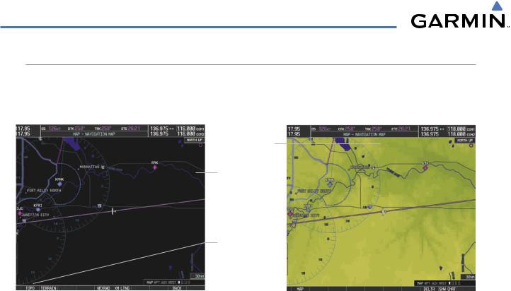
Distance and bearing from the aircraft’s present position to any point on the viewable navigation map may be calculated using the ‘Measure Bearing and Distance’ selection from Navigation Map page menu. The bearing and distance tool displays a dashed Measurement Line and a Measure Pointer to aid in graphically identifying points with which to measure. Lat/Long, distance and elevation data for the Measure Pointer is provided in a window at the top of the navigation map.
Measuring bearing and distance between any two points:
1)Press the MENU Key (with the Navigation Map Page displayed).
2)Highlight the ‘Measure Bearing/Distance’ field.
3)Press the ENT Key. A Measure Pointer is displayed on the map at the aircraft’s present position.
4)Move the Joystick to place the reference pointer at the desired location. The bearing and distance are displayed at the top of the map. Elevation at the current pointer position is also displayed. Pressing the ENT Key changes the starting point for measuring.
5)To exit the Measure Bearing/Distance option, press the Joystick; or select ‘Stop Measuring’ from the Page Menu and press the ENT Key.
Measurement |
|
|
|
Pointer Lat/Long |
|
|
|||
Information |
|
|
Measurement Line
Figure 5-13 Navigation Map - Measuring Bearing and Distance
190-00498-03 Rev.A |
Garmin G1000 Pilot’s Guide for Cessna Nav III |
5-13 |
FLIGHT MANAGEMENT
TOPOGRAPHY
All navigation maps can display various shades of topography colors representing land elevation, similar to aviation sectional charts. Topographic data can be displayed or removed as described in the following procedures.
Navigation Map
Topographic Data
Navigation Map
Black Background
|
TOPO Softkey |
|
||
|
Not Enabled |
|
||
|
TOPO Softkey |
|
|
|
|
|
|
||
TOPO Off |
Enabled |
TOPO On |
||
|
|
|
||
Figure 5-14 |
Navigation Map - Topographic Data |
|
Displaying/removing topographic data on all pages displaying navigation maps:
1)Press the MAP Softkey (the INSET Softkey for the PFD Inset Map).
2)Press the TOPO Softkey.
3)Press the TOPO Softkey again to remove topographic data from the Navigation Map. When topographic data is removed from the page, all navigation data is presented on a black background.
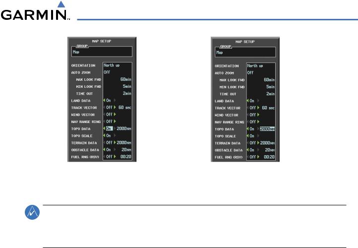
Displaying/removing topographic data (TOPO DATA) using the Navigation Map Page Menu:
1)Press the MENU Key with the Navigation Map Page displayed. The cursor flashes on the ‘Map Setup’ option.
2)Press the ENT Key. The Map Setup Menu is displayed.
3)Select the ‘Map’ group.
4)Press the ENT Key.
5)Highlight the ‘TOPO DATA’ field.
6)Select ‘On’ or ‘Off’.
7)Press the FMS Knob to return to the Navigation Map Page.
5-14 |
Garmin G1000 Pilot’s Guide for Cessna Nav III |
190-00498-03 Rev.A |
FLIGHT MANAGEMENT
|
TOPO DATA |
|
TOPO DATA |
|
|
||
|
On/Off |
Range |
Figure 5-15 Navigation Map Setup Menu - TOPO DATA Setup
The topographic data range is the maximum map range on which topographic data is displayed.
NOTE: Since the PFD Inset Map is much smaller than the MFD navigation maps, items are removed on the PFD Inset Map two range levels smaller than the range selected in the Map Setup pages (e.g., a setting of 100 nm removes the item at ranges above 100 nm on MFD navigation maps, while the PFD Inset Map removes the same item at 50 nm).
Selecting a topographical data range (TOPO DATA):
1)Press the MENU Key with the Navigation Map Page displayed. The cursor flashes on the ‘Map Setup’ option.
2)Press the ENT Key. The Map Setup Menu is displayed.
3)Select the ‘Map’ group.
4)Press the ENT Key.
5)Highlight the ‘TOPO DATA’ range field. TOPO ranges are from 500 ft to 2000 nm.
6)To change the TOPO range setting, turn the small FMS Knob to display the range list.
7)Select the desired range using the small FMS Knob.
8)Press the ENT Key.
9)Press the FMS Knob to return to the Navigation Map Page.
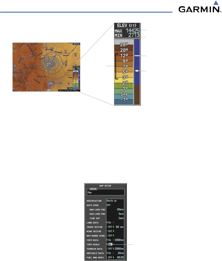
In addition, the Navigation Map can display a topographic scale (located in the lower right hand side of the map) showing a scale of the terrain elevation and current elevation values as shown following.
190-00498-03 Rev.A |
Garmin G1000 Pilot’s Guide for Cessna Nav III |
5-15 |
FLIGHT MANAGEMENT
Range of
Displayed
Elevations
Maximum Displayed Elevation
Minimum Displayed Elevation
Aircraft Altitude (MSL)
Ground Elevation at Pointer Location (only visible when Pointer is displayed)
Figure 5-16 Navigation Map - TOPO SCALE
Displaying/removing the topographic scale (TOPO SCALE):
1)Press the MENU Key with the Navigation Map Page displayed. The cursor flashes on the ‘Map Setup’ option.
2)Press the ENT Key. The Map Setup Menu is displayed.
3)Select the ‘Map’ group and press the ENT Key.
4)Highlight the ‘TOPO SCALE’ field.
5)Select ‘On’ or ‘Off’.
6)Press the FMS Knob to return to the Navigation Map Page.
TOPO SCALE
On/Off
Figure 5-17 Navigation Map Setup Menu - TOPO SCALE Setup
5-16 |
Garmin G1000 Pilot’s Guide for Cessna Nav III |
190-00498-03 Rev.A |