

- •Section 1 System Overview
- •1.1 System Description
- •1.2 Line Replaceable Units (LRU)
- •1.3 G1000 Controls
- •PFD/MFD Controls
- •Audio Panel Controls
- •1.4 Secure Digital (SD) Cards
- •1.5 System Power-up
- •1.6 System Operation
- •Normal Display Operation
- •Reversionary Display Operation
- •AHRS Operation
- •G1000 System Annunciations
- •Softkey Function
- •GPS Receiver Operation
- •1.7 Accessing G1000 Functionality
- •Menus
- •MFD Page Groups
- •MFD System Pages
- •1.8 Display Backlighting
- •Automatic Adjustment
- •Manual Adjustment
- •Section 2 Flight Instruments
- •2.1 Flight Instruments
- •Airspeed Indicator
- •Attitude Indicator
- •Altimeter
- •Vertical Speed Indicator (VSI)
- •Vertical Deviation
- •Horizontal Situation Indicator (HSI)
- •Course Deviation Indicator (CDI)
- •2.2 Supplemental Flight Data
- •Outside Air Temperature
- •Wind Data
- •Vertical Navigation (VNV) Indications
- •2.3 PFD Annunciations and Alerting Functions
- •G1000 System Alerting
- •Marker Beacon Annunciations
- •Traffic Annunciation
- •TAWS Annunciations
- •Altitude Alerting
- •Low Altitude Annunciation
- •Minimum Descent Altitude/Decision Height Alerting
- •2.4 Abnormal Operations
- •Abnormal GPS Conditions
- •Unusual Attitudes
- •Section 3 Engine Indication System (EIS)
- •3.1 Engine Display
- •3.2 Lean Display
- •Normally-aspirated Aircraft
- •Turbocharged Aircraft
- •3.3 System Display
- •Section 4 audio panel and CNS
- •4.1 Overview
- •MFD/PFD Controls and Frequency Display
- •Audio Panel Controls
- •4.2 COM Operation
- •COM Transceiver Selection and Activation
- •COM Transceiver Manual Tuning
- •Quick-Tuning and Activating 121.500 MHz
- •Auto-tuning the COM Frequency
- •Frequency Spacing
- •Automatic Squelch
- •Volume
- •4.3 NAV Operation
- •NAV Radio Selection and Activation
- •NAV Receiver Manual Tuning
- •Auto-tuning a NAV Frequency from the MFD
- •Marker Beacon Receiver
- •DME Tuning (Optional)
- •4.4 GTX 33 Mode S Transponder
- •Transponder Controls
- •Transponder Mode Selection
- •Entering a Transponder Code
- •IDENT Function
- •Flight ID Reporting
- •4.5 Additional Audio Panel Functions
- •Power-Up
- •Mono/Stereo Headsets
- •Speaker
- •Intercom
- •Passenger Address (PA) System
- •Clearance Recorder and Player
- •Entertainment Inputs
- •4.6 Audio Panel Preflight Procedure
- •4.7 Abnormal Operation
- •Stuck Microphone
- •COM Tuning Failure
- •Audio Panel Fail-Safe Operation
- •Reversionary Mode
- •Section 5 Flight Management
- •5.1 Introduction
- •Navigation Status Box
- •5.2 Using Map Displays
- •Map Orientation
- •Map Range
- •Map Panning
- •Measuring Bearing and Distance
- •Topography
- •Map Symbols
- •Airways
- •Track Vector
- •Wind Vector
- •Nav Range Ring
- •Fuel Range Ring
- •5.3 Waypoints
- •Airports
- •Intersections
- •NDBs
- •VORs
- •User Waypoints
- •5.4 Airspaces
- •5.5 Direct-to-Navigation
- •5.6 Flight Planning
- •Flight Plan Creation
- •Adding Waypoints To An Existing Flight Plan
- •Adding Airways to a Flight Plan
- •Adding Procedures To A Stored Flight Plan
- •Flight Plan Storage
- •Flight Plan Editing
- •Along Track Offsets
- •Parallel Track
- •Activating a Flight Plan Leg
- •Inverting a Flight Plan
- •Flight Plan Views
- •Closest Point of FPL
- •5.7 Vertical Navigation
- •Altitude Constraints
- •5.8 Procedures
- •Departures
- •Arrivals
- •Approaches
- •5.9 Trip Planning
- •Trip Planning
- •5.10 RAIM Prediction
- •5.11 Navigating a Flight Plan
- •5.12 Abnormal Operation
- •Section 6 Hazard Avoidance
- •6.1 XM Satellite Weather
- •Activating Services
- •Using XM Satellite Weather Products
- •6.2 WX-500 Stormscope (Optional)
- •Setting Up Stormscope on the Navigation Map
- •Selecting the Stormscope Page
- •6.3 Terrain Proximity
- •Displaying Terrain Proximity Data
- •Terrain Proximity Page
- •6.4 TAWs (Optional)
- •Displaying TAWS Data
- •TAWS Page
- •TAWS Alerts
- •System Status
- •6.5 Traffic Information Service (TIS)
- •Displaying TRAFFIC Data
- •Traffic Map Page
- •TIS Alerts
- •System Status
- •6.6 Traffic Advisory System (TAS) (Optional)
- •TAS Symbology
- •Operation
- •Altitude Display
- •Traffic Map Page Display Range
- •TAS Alerts
- •System Status
- •6.7 ADS-B Traffic (Optional)
- •Section 7 Automatic Flight Control System
- •7.2 Flight Director Operation
- •Activating the Flight Director
- •AFCS Status Box
- •Command Bars
- •Flight Director Modes
- •7.3 Vertical Modes
- •Pitch Hold Mode (PIT)
- •Selected Altitude capture Mode (ALTs)
- •Altitude hold mode (alt)
- •Vertical Speed Mode (VS)
- •Flight Level Change Mode (FLC)
- •Vertical Navigation Modes (VPTH, ALTV)
- •Glidepath Mode (GP) (waas only)
- •Glideslope Mode (GS)
- •Go Around (GA) Mode
- •7.4 Lateral Modes
- •Roll Hold Mode (ROL)
- •Heading Select Mode (HDG)
- •Navigation mode (GPS, VOR, LOC)
- •Approach mode (GPS, VAPP, LOC)
- •Backcourse Mode (BC)
- •7.5 Autopilot Operation
- •Engaging the Autopilot
- •Control Wheel Steering
- •Disengaging the Autopilot
- •7.6 Example Procedures
- •Departure
- •Intercepting a VOR Radial
- •Flying a Flight Plan/GPS Course
- •Descent
- •Approach
- •Go Around/Missed Approach
- •7.7 AFCS Annunciations and Alerts
- •AFCS Status Alerts
- •Overspeed Protection
- •Section 8 Additional Features
- •8.1 SafeTaxi
- •SafeTaxi Cycle Number and Revision
- •8.2 ChartView
- •ChartView Softkeys
- •Terminal Procedures Charts
- •Chart Options
- •Day/Night View
- •ChartView Cycle Number and Expiration Date
- •8.3 FliteCharts
- •FliteCharts Softkeys
- •Terminal Procedures Charts
- •Chart Options
- •Day/Night View
- •FliteCharts Cycle Number and Expiration Date
- •8.4 XM Radio Entertainment (Optional)
- •Activating XM Satellite Radio Services
- •Using XM Radio
- •Automatic Audio Muting
- •8.5 Scheduler
- •8.5 Abnormal Operation
- •Annunciations and Alerts
- •Alert Level Definitions
- •Nav III Aircraft Alerts
- •CO Guardian Messages
- •G1000 System Annunciations
- •Other G1000 Aural Alerts
- •G1000 System Message Advisories
- •AFCS Alerts
- •TAWS ALERTS
- •TAWS System Status Annunciations
- •SD Card Use
- •Jeppesen Databases
- •Garmin Databases
- •Glossary
- •Frequently Asked Questions
- •General TIS Information
- •Introduction
- •TIS vs. TAS/TCAS
- •TIS Limitations
- •Map Symbols
- •Index

HAZARD AVOIDANCE
ALTITUDE DISPLAY
Changing the altitude display mode:
1)On the Traffic Page, press the ALT MODE Softkey.
2)Press one of the following Softkeys:
•BELOW
•NORMAL
•ABOVE
•UNREST (unrestricted)
3)To return to the Traffic Page, press the BACK Softkey.
Or:
1)Press the MENU Key.
2)Turn the small FMS Knob to select one of the following:
•BELOW
•NORMAL
•ABOVE
•UNREST (unrestricted)
3)Press the ENT Softkey.
TRAFFIC MAP PAGE DISPLAY RANGE
The display range on the Traffic Map Page can be changed at any time. Map range is adjustable with the RANGE Knob from 2 to 40 nm, as indicated by the map range rings.
Changing the display range on the Traffic Page:
1)Turn the RANGE Knob.
2)The following range options are available:
•2 nm
•2 and 6 nm
•6 and 12 nm
•12 and 24 nm
•24 and 40 nm
6-60 |
Garmin G1000 Pilot’s Guide for Cessna Nav III |
190-00498-03 Rev.A |
HAZARD AVOIDANCE
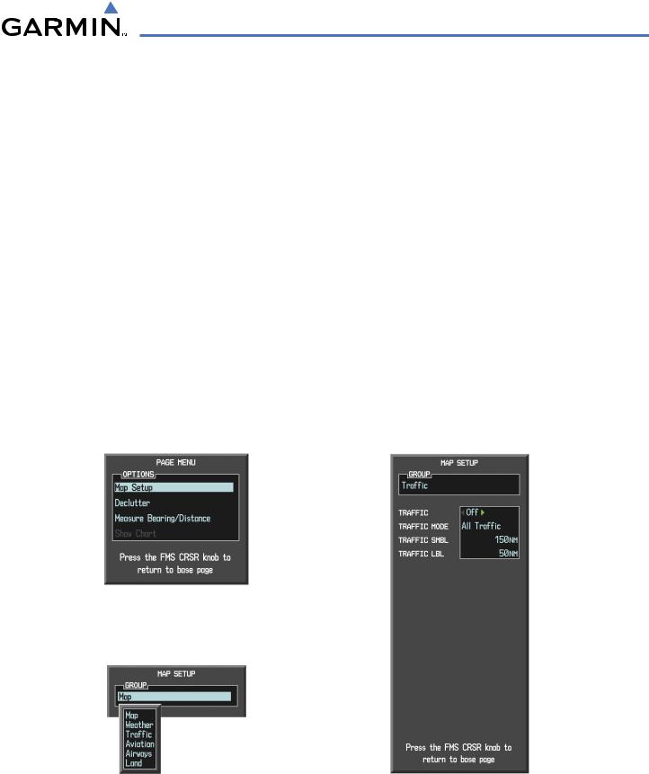
Customizing the traffic display on the Navigation Map Page:
1)Select the Navigation Map Page.
2)Press the MENU Key.
3)With Map Setup highlighted, press the ENT Key (Figure 6-74).
4)Turn the small FMS Knob to select the Traffic Group and press the ENT Key (Figure 6-75).
5)Turn the large FMS Knob or press the ENT Key to scroll though the selections (Figure 6-76).
•TRAFFIC – Turns the display of traffic data on or off
•TRAFFIC MODE – Selects the traffic mode for display; select from:
-All Traffic - Displays all traffic
-TA/PA - Displays Traffic Alerts and Proximity Advisories
-TA ONLY - Displays Traffic Alerts only
•TRAFFIC SMBL – Selects the maximum range at which traffic symbols are shown
•TRAFFIC LBL – Selects the maximum range at which traffic labels are shown with the option to turn off
6)Turn the small FMS Knob to scroll though options (ON/OFF, range settings, etc.).
7)Press the ENT Key to select an option.
8)Press the FMS Knob or CLR Key to return to the Navigation Map Page.
Figure 6-74 Navigation Map Page Menu
Figure 6-75 Navigation Map Page Setup Menu |
Figure 6-76 Navigation Map Page Setup Menu,Traffic Group |
190-00498-03 Rev.A |
Garmin G1000 Pilot’s Guide for Cessna Nav III |
6-61 |
HAZARD AVOIDANCE
TAS ALERTS
 NOTE: Refer to the KTA 870 documentation for information on alerts generated by the TAS equipment.
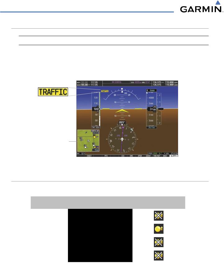
When the number of TAs on the Traffic Map Page increases from one scan to the next, the following occur:
•A TRAFFIC Annunciation appears at the top right of the airspeed on the PFD, flashing for 5 seconds and remaining displayed until no TAs are detected in the area.
•The PFD Inset Map is automatically displayed with TA traffic.
Inset Map
Displays When
TA is Detected
Figure 6-77 Traffic Annunciation (PFD)
SYSTEM STATUS
The traffic mode is annunciated in the upper left corner of the Traffic Map Page.
Mode |
Traffic Mode Annunciation |
Traffic Display Enabled Icon |
|
(Traffic Map Page) |
(Other Maps) |
||
|
|||
TAS Self-test Initiated |
TEST |
|
|
(also shown in white in center of page) |
|
||
|
|
|
|
TAS Operating |
OPERATING |
|
|
|
|
|
|
TAS Standby |
STANDBY |
|
|
(also shown in white in center of page) |
|
||
|
|
||
TAS Failed* |
FAIL |
|
|
|
|
|
* See Table 6-16 for additional failure annunciations
Table 6-15 TAS Modes
If the unit fails, an annunciation as to the cause of the failure is shown in the center of the Traffic Map Page.
6-62 |
Garmin G1000 Pilot’s Guide for Cessna Nav III |
190-00498-03 Rev.A |

HAZARD AVOIDANCE
Traffic Map Page |
Description |
|
Annunciation |
||
|
||
NO DATA |
Data is not being received from the TAS unit |
|
DATA FAILED |
Data is being received from the TAS unit, but the |
|
unit is self-reporting a failure |
||
|
||
FAILED |
Incorrect data format received from the TAS unit |
Table 6-16 TAS Failure Annunciations
The annumciations to indicate the status of traffic information appear in a banner at the lower left corner of maps on which traffic can be displayed.
Traffic Status Banner |
Description |
|
Annunciation |
||
|
||
|
A Traffic Advisory is outside the selected display range* |
|
TA OFF SCALE |
Annunciation is removed when traffic comes within |
|
|
the selected display range |
|
|
System cannot determine bearing of Traffic Advisory** |
|
TA X.X ± XX ↕ |
Annunciation indicates distance in nm, altitude |
|
separation in hundreds of feet, and altitude trend |
||
|
||
|
arrow (climbing/descending) |
|
TRFC FAIL |
TAS unit has failed (unit is self-reporting a failure or |
|
sending incorrectly formatted data) |
||
|
||
NO TRFC DATA |
Data is not being received from the TAS unit |
*Shown as symbol on Traffic Map Page **Shown in center of Traffic Map Page
Table 6-17 TAS Traffic Status Annunciations
190-00498-03 Rev.A |
Garmin G1000 Pilot’s Guide for Cessna Nav III |
6-63 |