

- •Section 1 System Overview
- •1.1 System Description
- •1.2 Line Replaceable Units (LRU)
- •1.3 G1000 Controls
- •PFD/MFD Controls
- •Audio Panel Controls
- •1.4 Secure Digital (SD) Cards
- •1.5 System Power-up
- •1.6 System Operation
- •Normal Display Operation
- •Reversionary Display Operation
- •AHRS Operation
- •G1000 System Annunciations
- •Softkey Function
- •GPS Receiver Operation
- •1.7 Accessing G1000 Functionality
- •Menus
- •MFD Page Groups
- •MFD System Pages
- •1.8 Display Backlighting
- •Automatic Adjustment
- •Manual Adjustment
- •Section 2 Flight Instruments
- •2.1 Flight Instruments
- •Airspeed Indicator
- •Attitude Indicator
- •Altimeter
- •Vertical Speed Indicator (VSI)
- •Vertical Deviation
- •Horizontal Situation Indicator (HSI)
- •Course Deviation Indicator (CDI)
- •2.2 Supplemental Flight Data
- •Outside Air Temperature
- •Wind Data
- •Vertical Navigation (VNV) Indications
- •2.3 PFD Annunciations and Alerting Functions
- •G1000 System Alerting
- •Marker Beacon Annunciations
- •Traffic Annunciation
- •TAWS Annunciations
- •Altitude Alerting
- •Low Altitude Annunciation
- •Minimum Descent Altitude/Decision Height Alerting
- •2.4 Abnormal Operations
- •Abnormal GPS Conditions
- •Unusual Attitudes
- •Section 3 Engine Indication System (EIS)
- •3.1 Engine Display
- •3.2 Lean Display
- •Normally-aspirated Aircraft
- •Turbocharged Aircraft
- •3.3 System Display
- •Section 4 audio panel and CNS
- •4.1 Overview
- •MFD/PFD Controls and Frequency Display
- •Audio Panel Controls
- •4.2 COM Operation
- •COM Transceiver Selection and Activation
- •COM Transceiver Manual Tuning
- •Quick-Tuning and Activating 121.500 MHz
- •Auto-tuning the COM Frequency
- •Frequency Spacing
- •Automatic Squelch
- •Volume
- •4.3 NAV Operation
- •NAV Radio Selection and Activation
- •NAV Receiver Manual Tuning
- •Auto-tuning a NAV Frequency from the MFD
- •Marker Beacon Receiver
- •DME Tuning (Optional)
- •4.4 GTX 33 Mode S Transponder
- •Transponder Controls
- •Transponder Mode Selection
- •Entering a Transponder Code
- •IDENT Function
- •Flight ID Reporting
- •4.5 Additional Audio Panel Functions
- •Power-Up
- •Mono/Stereo Headsets
- •Speaker
- •Intercom
- •Passenger Address (PA) System
- •Clearance Recorder and Player
- •Entertainment Inputs
- •4.6 Audio Panel Preflight Procedure
- •4.7 Abnormal Operation
- •Stuck Microphone
- •COM Tuning Failure
- •Audio Panel Fail-Safe Operation
- •Reversionary Mode
- •Section 5 Flight Management
- •5.1 Introduction
- •Navigation Status Box
- •5.2 Using Map Displays
- •Map Orientation
- •Map Range
- •Map Panning
- •Measuring Bearing and Distance
- •Topography
- •Map Symbols
- •Airways
- •Track Vector
- •Wind Vector
- •Nav Range Ring
- •Fuel Range Ring
- •5.3 Waypoints
- •Airports
- •Intersections
- •NDBs
- •VORs
- •User Waypoints
- •5.4 Airspaces
- •5.5 Direct-to-Navigation
- •5.6 Flight Planning
- •Flight Plan Creation
- •Adding Waypoints To An Existing Flight Plan
- •Adding Airways to a Flight Plan
- •Adding Procedures To A Stored Flight Plan
- •Flight Plan Storage
- •Flight Plan Editing
- •Along Track Offsets
- •Parallel Track
- •Activating a Flight Plan Leg
- •Inverting a Flight Plan
- •Flight Plan Views
- •Closest Point of FPL
- •5.7 Vertical Navigation
- •Altitude Constraints
- •5.8 Procedures
- •Departures
- •Arrivals
- •Approaches
- •5.9 Trip Planning
- •Trip Planning
- •5.10 RAIM Prediction
- •5.11 Navigating a Flight Plan
- •5.12 Abnormal Operation
- •Section 6 Hazard Avoidance
- •6.1 XM Satellite Weather
- •Activating Services
- •Using XM Satellite Weather Products
- •6.2 WX-500 Stormscope (Optional)
- •Setting Up Stormscope on the Navigation Map
- •Selecting the Stormscope Page
- •6.3 Terrain Proximity
- •Displaying Terrain Proximity Data
- •Terrain Proximity Page
- •6.4 TAWs (Optional)
- •Displaying TAWS Data
- •TAWS Page
- •TAWS Alerts
- •System Status
- •6.5 Traffic Information Service (TIS)
- •Displaying TRAFFIC Data
- •Traffic Map Page
- •TIS Alerts
- •System Status
- •6.6 Traffic Advisory System (TAS) (Optional)
- •TAS Symbology
- •Operation
- •Altitude Display
- •Traffic Map Page Display Range
- •TAS Alerts
- •System Status
- •6.7 ADS-B Traffic (Optional)
- •Section 7 Automatic Flight Control System
- •7.2 Flight Director Operation
- •Activating the Flight Director
- •AFCS Status Box
- •Command Bars
- •Flight Director Modes
- •7.3 Vertical Modes
- •Pitch Hold Mode (PIT)
- •Selected Altitude capture Mode (ALTs)
- •Altitude hold mode (alt)
- •Vertical Speed Mode (VS)
- •Flight Level Change Mode (FLC)
- •Vertical Navigation Modes (VPTH, ALTV)
- •Glidepath Mode (GP) (waas only)
- •Glideslope Mode (GS)
- •Go Around (GA) Mode
- •7.4 Lateral Modes
- •Roll Hold Mode (ROL)
- •Heading Select Mode (HDG)
- •Navigation mode (GPS, VOR, LOC)
- •Approach mode (GPS, VAPP, LOC)
- •Backcourse Mode (BC)
- •7.5 Autopilot Operation
- •Engaging the Autopilot
- •Control Wheel Steering
- •Disengaging the Autopilot
- •7.6 Example Procedures
- •Departure
- •Intercepting a VOR Radial
- •Flying a Flight Plan/GPS Course
- •Descent
- •Approach
- •Go Around/Missed Approach
- •7.7 AFCS Annunciations and Alerts
- •AFCS Status Alerts
- •Overspeed Protection
- •Section 8 Additional Features
- •8.1 SafeTaxi
- •SafeTaxi Cycle Number and Revision
- •8.2 ChartView
- •ChartView Softkeys
- •Terminal Procedures Charts
- •Chart Options
- •Day/Night View
- •ChartView Cycle Number and Expiration Date
- •8.3 FliteCharts
- •FliteCharts Softkeys
- •Terminal Procedures Charts
- •Chart Options
- •Day/Night View
- •FliteCharts Cycle Number and Expiration Date
- •8.4 XM Radio Entertainment (Optional)
- •Activating XM Satellite Radio Services
- •Using XM Radio
- •Automatic Audio Muting
- •8.5 Scheduler
- •8.5 Abnormal Operation
- •Annunciations and Alerts
- •Alert Level Definitions
- •Nav III Aircraft Alerts
- •CO Guardian Messages
- •G1000 System Annunciations
- •Other G1000 Aural Alerts
- •G1000 System Message Advisories
- •AFCS Alerts
- •TAWS ALERTS
- •TAWS System Status Annunciations
- •SD Card Use
- •Jeppesen Databases
- •Garmin Databases
- •Glossary
- •Frequently Asked Questions
- •General TIS Information
- •Introduction
- •TIS vs. TAS/TCAS
- •TIS Limitations
- •Map Symbols
- •Index
HAZARD AVOIDANCE
6.2 WX-500 STORMSCOPE (OPTIONAL)
 NOTE: TheStormscopesystemisnotintendedforhazardousthunderstormpenetration. Weatherinformation on the G1000 MFD is approved for weather avoidance only. Refer to theWX-500 User’s Guide for a detailed description of Stormscope operation.
 NOTE: L-3 STORMSCOPE® WX-500 Lightning and GDL 69/69A XM® Satellite Weather Lightning are mutually exclusive.
The following pages can display Stormscope data: |
|
• Stormscope Page |
• AUX - Trip Planning Page |
• Navigation Map |
• Nearest Pages |
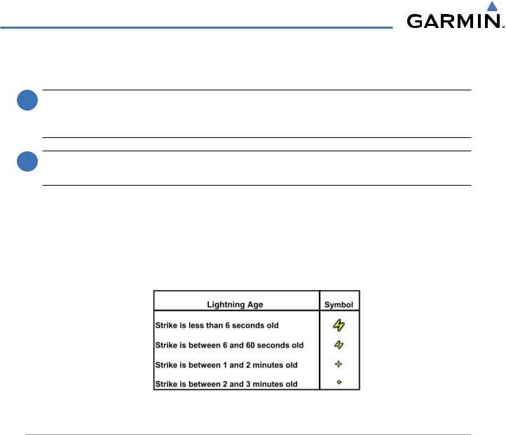
To display Stormscope data on the Navigation Map, AUX - Trip Planning Page, or any of the Nearest Pages, press the MAP Softkey, then press the STRMSCP Softkey. These pages can also display cell or strike data using the yellow lightning strike symbology shown in Table 6-3.
Table 6-3 Lightning Age and Symbols
SETTING UP STORMSCOPE ON THE NAVIGATION MAP
Setting up Stormscope options on the Navigation Map:
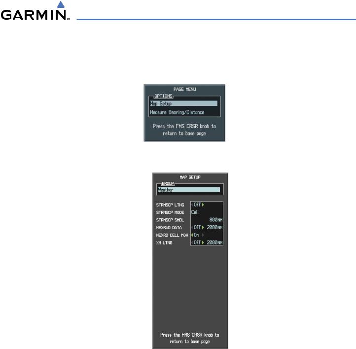
1)On the Navigation Map Page, press the MENU Key.
2)With ‘Map Setup’ selected (Figure 6-38), press the ENT Key.
3)Turn the small FMS Knob to display the group selection window. Turn the small FMS Knob to select ‘Weather’ (Figure 6-39), and press the ENT Key.
4)Turn the large FMS Knob to highlight and move between the product selections.
5)When an item is highlighted, turn the small FMS Knob to select the option.
6)Press the ENT Key.
7)Press the FMS Knob to return to the Navigation Map Page (Figure 6-40).
The following options are available (Figure 6-39):
• STRMSCP LTNG – Turns the display of Stormscope data on or off.
6-26 |
Garmin G1000 Pilot’s Guide for Cessna Nav III |
190-00498-03 Rev.A |
HAZARD AVOIDANCE
•STRMSCP MODE – Selects the CELL or STRIKE mode of lightning activity. Cell mode identifies clusters or cells of electrical activity. Strike mode indicates the approximate location of lightning strikes.
•STRMSCP SMBL – Selects the range at which Stormscope data displays. Stormscope data is removed when a map range greater than the STRMSCP SMBL value is selected.
Figure 6-38 Page Menu
Figure 6-39 Map Setup Menu
CELL AND STRIKE MODE ON THE NAVIGATION MAP
On the Navigation Map, cell mode identifies cells of lightning activity (Figure 6-40). Stormscope identifies clusters of electrical activity that indicate cells. Strike mode indicates the approximate location of lightning strikes.
Selecting the ‘cell’ or ‘strike’ mode on the Navigation Map:
1)Press the MENU Key.
2)With ‘Map Setup’ selected, press the ENT Key.
3)Select the ‘Weather’ group.
4)Press the ENT Key. The cursor flashes on ‘STRMSCP LTNG’.
190-00498-03 Rev.A |
Garmin G1000 Pilot’s Guide for Cessna Nav III |
6-27 |
HAZARD AVOIDANCE
5)Turn the large FMS Knob to select ‘STRMSCP MODE’.
6)Turn the small FMS Knob to change between ‘CELL’ and ‘STRIKE’ options. When an item is selected, press the ENT Key.
7)Press the FMS knob to return to the Navigation Map Page.
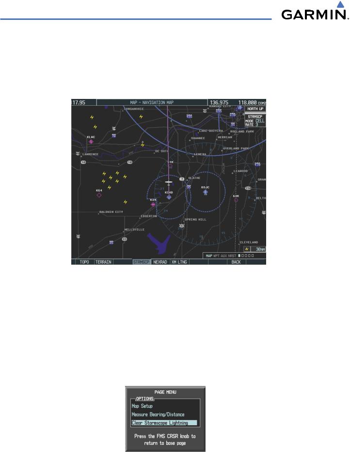
Figure 6-40 Navigation Map Page with Stormscope
Lightning Data
If heading input is lost, strikes and/or cells must be cleared manually after the execution of each turn (Figure 6-41). This is to ensure that the strike and/or cell positions are depicted accurately in relation to the nose of the aircraft.
Manually clearing Stormscope data on the Navigation Map:
1)Press the MENU Key.
2)Select ‘Clear Stormscope Lightning’.
3)Press the ENT Key.
Figure 6-41 Navigation Map Page Options Menu
6-28 |
Garmin G1000 Pilot’s Guide for Cessna Nav III |
190-00498-03 Rev.A |
HAZARD AVOIDANCE
ZOOM RANGE ON THE NAVIGATION MAP
Stormscopelightningdatacanbedisplayedupto800nmzoomrange(inNorthupmode)ontheNavigation Map Page. However, in the track up mode at the 500 nm range, a portion of Stormscope lightning data can be behind the aircraft and therefore not visible on the Navigation Map. Since the range for Stormscope data is 400 nm diameter total (200 nm in front and 200 nm behind), the 500 nm range in North up mode shows all the data.
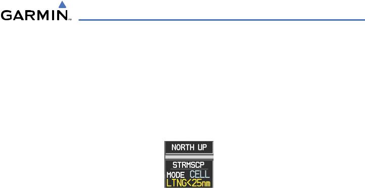
At a map range of less than 25 nm, Stormscope lightning data is not displayed, but can still be present. The presence of Stormscope lightning data is indicated by the annunciation ‘LTNG < 25 nm’ in the upper right corner (Figure 6-42).
Figure 6-42 Lightning Display Range Annunciation
The maximum zoom range can also be set on the Navigation Map. Note that Stormscope data above the selected maximum zoom range is decluttered.
Selecting a Stormscope range on the Navigation Map:
1)Press the MENU Key.
2)Select ‘MAP SETUP’.
3)Select the ‘Weather’ group.
4)Press the ENT Key.
5)Turn the large FMS Knob to select ‘STRMSCP SMBL’.
6)Turn the small FMS Knob to select the maximum display range.
7)Press the ENT Key.
8)Press the FMS Knob to return to the Navigation Map Page.
To change the display range on the Navigation Map Page, turn the RANGE Knob clockwise to zoom out or counter-clockwise to zoom in.
190-00498-03 Rev.A |
Garmin G1000 Pilot’s Guide for Cessna Nav III |
6-29 |