

- •Section 1 System Overview
- •1.1 System Description
- •1.2 Line Replaceable Units (LRU)
- •1.3 G1000 Controls
- •PFD/MFD Controls
- •Audio Panel Controls
- •1.4 Secure Digital (SD) Cards
- •1.5 System Power-up
- •1.6 System Operation
- •Normal Display Operation
- •Reversionary Display Operation
- •AHRS Operation
- •G1000 System Annunciations
- •Softkey Function
- •GPS Receiver Operation
- •1.7 Accessing G1000 Functionality
- •Menus
- •MFD Page Groups
- •MFD System Pages
- •1.8 Display Backlighting
- •Automatic Adjustment
- •Manual Adjustment
- •Section 2 Flight Instruments
- •2.1 Flight Instruments
- •Airspeed Indicator
- •Attitude Indicator
- •Altimeter
- •Vertical Speed Indicator (VSI)
- •Vertical Deviation
- •Horizontal Situation Indicator (HSI)
- •Course Deviation Indicator (CDI)
- •2.2 Supplemental Flight Data
- •Outside Air Temperature
- •Wind Data
- •Vertical Navigation (VNV) Indications
- •2.3 PFD Annunciations and Alerting Functions
- •G1000 System Alerting
- •Marker Beacon Annunciations
- •Traffic Annunciation
- •TAWS Annunciations
- •Altitude Alerting
- •Low Altitude Annunciation
- •Minimum Descent Altitude/Decision Height Alerting
- •2.4 Abnormal Operations
- •Abnormal GPS Conditions
- •Unusual Attitudes
- •Section 3 Engine Indication System (EIS)
- •3.1 Engine Display
- •3.2 Lean Display
- •Normally-aspirated Aircraft
- •Turbocharged Aircraft
- •3.3 System Display
- •Section 4 audio panel and CNS
- •4.1 Overview
- •MFD/PFD Controls and Frequency Display
- •Audio Panel Controls
- •4.2 COM Operation
- •COM Transceiver Selection and Activation
- •COM Transceiver Manual Tuning
- •Quick-Tuning and Activating 121.500 MHz
- •Auto-tuning the COM Frequency
- •Frequency Spacing
- •Automatic Squelch
- •Volume
- •4.3 NAV Operation
- •NAV Radio Selection and Activation
- •NAV Receiver Manual Tuning
- •Auto-tuning a NAV Frequency from the MFD
- •Marker Beacon Receiver
- •DME Tuning (Optional)
- •4.4 GTX 33 Mode S Transponder
- •Transponder Controls
- •Transponder Mode Selection
- •Entering a Transponder Code
- •IDENT Function
- •Flight ID Reporting
- •4.5 Additional Audio Panel Functions
- •Power-Up
- •Mono/Stereo Headsets
- •Speaker
- •Intercom
- •Passenger Address (PA) System
- •Clearance Recorder and Player
- •Entertainment Inputs
- •4.6 Audio Panel Preflight Procedure
- •4.7 Abnormal Operation
- •Stuck Microphone
- •COM Tuning Failure
- •Audio Panel Fail-Safe Operation
- •Reversionary Mode
- •Section 5 Flight Management
- •5.1 Introduction
- •Navigation Status Box
- •5.2 Using Map Displays
- •Map Orientation
- •Map Range
- •Map Panning
- •Measuring Bearing and Distance
- •Topography
- •Map Symbols
- •Airways
- •Track Vector
- •Wind Vector
- •Nav Range Ring
- •Fuel Range Ring
- •5.3 Waypoints
- •Airports
- •Intersections
- •NDBs
- •VORs
- •User Waypoints
- •5.4 Airspaces
- •5.5 Direct-to-Navigation
- •5.6 Flight Planning
- •Flight Plan Creation
- •Adding Waypoints To An Existing Flight Plan
- •Adding Airways to a Flight Plan
- •Adding Procedures To A Stored Flight Plan
- •Flight Plan Storage
- •Flight Plan Editing
- •Along Track Offsets
- •Parallel Track
- •Activating a Flight Plan Leg
- •Inverting a Flight Plan
- •Flight Plan Views
- •Closest Point of FPL
- •5.7 Vertical Navigation
- •Altitude Constraints
- •5.8 Procedures
- •Departures
- •Arrivals
- •Approaches
- •5.9 Trip Planning
- •Trip Planning
- •5.10 RAIM Prediction
- •5.11 Navigating a Flight Plan
- •5.12 Abnormal Operation
- •Section 6 Hazard Avoidance
- •6.1 XM Satellite Weather
- •Activating Services
- •Using XM Satellite Weather Products
- •6.2 WX-500 Stormscope (Optional)
- •Setting Up Stormscope on the Navigation Map
- •Selecting the Stormscope Page
- •6.3 Terrain Proximity
- •Displaying Terrain Proximity Data
- •Terrain Proximity Page
- •6.4 TAWs (Optional)
- •Displaying TAWS Data
- •TAWS Page
- •TAWS Alerts
- •System Status
- •6.5 Traffic Information Service (TIS)
- •Displaying TRAFFIC Data
- •Traffic Map Page
- •TIS Alerts
- •System Status
- •6.6 Traffic Advisory System (TAS) (Optional)
- •TAS Symbology
- •Operation
- •Altitude Display
- •Traffic Map Page Display Range
- •TAS Alerts
- •System Status
- •6.7 ADS-B Traffic (Optional)
- •Section 7 Automatic Flight Control System
- •7.2 Flight Director Operation
- •Activating the Flight Director
- •AFCS Status Box
- •Command Bars
- •Flight Director Modes
- •7.3 Vertical Modes
- •Pitch Hold Mode (PIT)
- •Selected Altitude capture Mode (ALTs)
- •Altitude hold mode (alt)
- •Vertical Speed Mode (VS)
- •Flight Level Change Mode (FLC)
- •Vertical Navigation Modes (VPTH, ALTV)
- •Glidepath Mode (GP) (waas only)
- •Glideslope Mode (GS)
- •Go Around (GA) Mode
- •7.4 Lateral Modes
- •Roll Hold Mode (ROL)
- •Heading Select Mode (HDG)
- •Navigation mode (GPS, VOR, LOC)
- •Approach mode (GPS, VAPP, LOC)
- •Backcourse Mode (BC)
- •7.5 Autopilot Operation
- •Engaging the Autopilot
- •Control Wheel Steering
- •Disengaging the Autopilot
- •7.6 Example Procedures
- •Departure
- •Intercepting a VOR Radial
- •Flying a Flight Plan/GPS Course
- •Descent
- •Approach
- •Go Around/Missed Approach
- •7.7 AFCS Annunciations and Alerts
- •AFCS Status Alerts
- •Overspeed Protection
- •Section 8 Additional Features
- •8.1 SafeTaxi
- •SafeTaxi Cycle Number and Revision
- •8.2 ChartView
- •ChartView Softkeys
- •Terminal Procedures Charts
- •Chart Options
- •Day/Night View
- •ChartView Cycle Number and Expiration Date
- •8.3 FliteCharts
- •FliteCharts Softkeys
- •Terminal Procedures Charts
- •Chart Options
- •Day/Night View
- •FliteCharts Cycle Number and Expiration Date
- •8.4 XM Radio Entertainment (Optional)
- •Activating XM Satellite Radio Services
- •Using XM Radio
- •Automatic Audio Muting
- •8.5 Scheduler
- •8.5 Abnormal Operation
- •Annunciations and Alerts
- •Alert Level Definitions
- •Nav III Aircraft Alerts
- •CO Guardian Messages
- •G1000 System Annunciations
- •Other G1000 Aural Alerts
- •G1000 System Message Advisories
- •AFCS Alerts
- •TAWS ALERTS
- •TAWS System Status Annunciations
- •SD Card Use
- •Jeppesen Databases
- •Garmin Databases
- •Glossary
- •Frequently Asked Questions
- •General TIS Information
- •Introduction
- •TIS vs. TAS/TCAS
- •TIS Limitations
- •Map Symbols
- •Index
FLIGHT MANAGEMENT
5.9 TRIP PLANNING
The G1000 allows the pilot to view trip planning information, fuel information, and other information for a specified flight plan or flight plan leg based on automatic data, or based on manually entered data. Weight planning is also available, based on fuel sensor data and the active flight plan (to estimate remaining fuel).
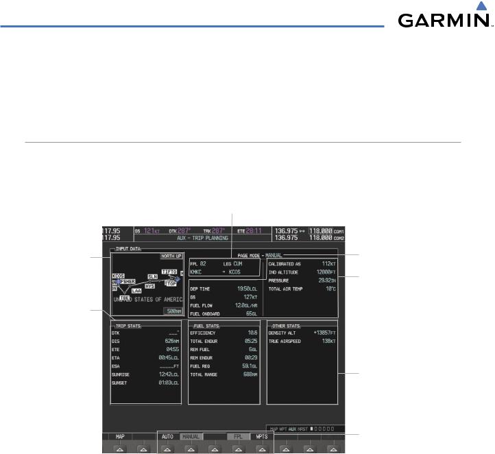
TRIP PLANNING
All of the input of data needed for calculation and viewing of the statistics is done on the Trip Planning Page located in the AUX Page Group.
Selected Flight Plan Segment
-FPL Number/Cumulative Legs (CUM or REM) or Leg Number (NN)
-Waypoints Defining Selected Flight Plan/Flight Plan Leg
Preview of Selected
Flight Plan/
Flight Plan Leg
Trip Statistics
Desired Track -
Distance -
Est. Time Enroute -
Est. Time of Arrival -
Enroute Safe Altitude -
Sunrise Time (local) -
Sunset Time (local -
Fuel Statistics
Efficiency -
Total Endurance -
Remaining Fuel -
Remaining Endurance -
Fuel Required -
Total Range -
Figure 5-94 Trip Planning Page
Trip Planning Page Mode
- Automatic/Manual
Trip Input Data (sensor/pilot)
-Departure Time (local)
-Ground Speed
-Fuel Flow
-Fuel On Board Aircraft
-Calibrated Airspeed
-Indicated Altitude
-Barometric Pressure
-Total Air Temperature
Other Statistics
-Density Altitude
-True Airspeed (TAS)
-Wind Direction/Speed
-Head/Tail Wind Speed
Softkeys
-Automatic/Manual Page Mode
-Flight Plan/Waypoint Mode
The trip planning inputs are based on sensor inputs (automatic page mode) or on pilot inputs (manual page mode). Some additional explanation of the sources for some of the inputs is as follows:
•Departure time (DEP TIME) - This defaults to the current time in automatic page mode. The computations are from the aircraft present position, so the aircraft is always just departing.
•Calibrated airspeed (CALIBRATED AS) - The primary source is from the air data system, and the secondary source of information is GPS ground speed.
•Indicated altitude (IND ALTITUDE) - The primary source is the barometric altitude, and the secondary source of information is GPS altitude.
5-102 |
Garmin G1000 Pilot’s Guide for Cessna Nav III |
190-00498-03 Rev.A |
FLIGHT MANAGEMENT
TRIP STATISTICS
The trip statistics are calculated based on the selected starting and ending waypoints and the trip planning inputs.
In flight plan mode (FPL) with a stored flight plan selected (NN), and the entire flight plan (CUM) selected, the waypoints are the starting and ending waypoints of the selected flight plan.
In flight plan mode (FPL) with a stored flight plan selected (NN), and a specific leg (NN) selected, the waypoints are the endpoints of the selected leg.
In flight plan mode (FPL) with the active flight plan selected (00), and the remaining flight plan (REM) selected, the ‘from’ waypoint is the present position of the aircraft and the ‘to’ waypoint is the endpoint of the active flight plan.
In flight plan mode (FPL) with the active flight plan selected (00), and a specific leg (NN) selected, the ‘from’ waypoint is the current aircraft position and the ‘to’ waypoint is the endpoint of the selected leg.
In waypoint (WPTS) mode these are manually selected waypoints (if there is an active flight plan, these default to the endpoints of the active leg).
Some of the calculated trip statistics are dashed when the selected leg of the active flight plan has already been flown.
•Desired Track (DTK) - DTK is shown as nnn° and is the desired track between the selected waypoints. It is dashed unless only a single leg is selected.
•Distance (DIS) - The distance is shown in tenths of units up to 99.9, and in whole units up to 9999.
•Estimated time enroute (ETE) - ETE is shown as hours:minutes until less than an hour, then it is shown as minutes:seconds.
•Estimated time of arrival (ETA) - ETA is shown as hours:minutes and is the local time at the destination.
-If in waypoint mode then the ETA is the ETE added to the departure time.
-If a flight plan other than the active flight plan is selected it shows the ETA by adding to the departure time all of the ETEs of the legs up to the selected leg. If the entire flight plan is selected, then the ETA is calculated as if the last leg of the flight plan was selected.
-If the active flight plan is selected the ETA reflects the current position of the aircraft and the current leg being flown. The ETA is calculated by adding to the current time the ETEs of the current leg up to and including the selected leg. If the entire flight plan is selected, then the ETA is calculated as if the last leg of the flight plan was selected.
•Enroute safe altitude (ESA) - The ESA is shown as nnnnnFT
•Destination sunrise and sunset times (SUNRISE, SUNSET) - These times are shown as hours:minutes and are the local time at the destination.
190-00498-03 Rev.A |
Garmin G1000 Pilot’s Guide for Cessna Nav III |
5-103 |

FLIGHT MANAGEMENT
FUEL STATISTICS
The fuel statistics are calculated based on the selected starting and ending waypoints and the trip planning inputs. Some of the calculated trip statistics are dashed when the selected leg of the active flight plan has already been flown.
•Fuel efficiency (EFFICIENCY) - This value is calculated by dividing the current ground speed by the current fuel flow.
•Time of fuel endurance (TOTAL ENDUR) - This time is shown as hours:minutes. This value is obtained by dividing the amount of fuel on board by the current fuel flow.
•Fuel on board upon reaching end of selected leg (REM FUEL) - This value is calculated by taking the amount of fuel onboard and subtracting the fuel required for trip.
•Fuel endurance remaining at end of selected leg (REM ENDUR) - This value is calculated by subtracting the time of fuel endurance by the amount of time to go.
•Fuel required for trip (FUEL REQ) - This value is calculated by multiplying the time to go by the fuel flow.
•Total range at entered fuel flow (TOTAL RANGE) - This value is calculated by multiplying the time of fuel endurance by the ground speed.
OTHER STATISTICS
These statistics are calculated based on the system sensor inputs or the manual trip planning inputs.
•Density altitude (DENSITY ALT)
•True airspeed (TRUE AIRSPEED)
•Wind direction (WIND DIRECTION) - Not shown in manual page mode.
•Wind speed (WIND SPEED) - Not shown in manual page mode.
•Head wind (HEAD WIND) - Not shown in manual page mode. The wind is shown as a tail wind value if appropriate
The pilot may select automatic (AUTO) or manual (MANUAL) page mode, and flight plan (FPL) or waypoint (WPTS) mode. In automatic page mode, only the FPL, LEG, or waypoint IDs are editable (based on FPL/WPTS selection).
Selected Flight Plan NN - 00 is Active FPL 01-99 are Stored FPLs
|
|
|
Selected Leg(s) |
|
|
|
Stored Flight Plan |
|
|
|
|
|
|
|
- CUM: Beginning to End of FPL |
|
|
|
|
|
|
|
- NN: Beginning to End of Selected Leg |
|
Starting and Ending Waypoint |
Active Flight Plan |
|
of Selected Flight Plan Segment |
- REM: Pres. Pos. to End of FPL |
||
|
|
|
- NN: Pres. Pos. to End of Selected Leg |
Figure 5-95 Trip Planning Page - Flight Plan Mode
5-104 |
Garmin G1000 Pilot’s Guide for Cessna Nav III |
190-00498-03 Rev.A |

FLIGHT MANAGEMENT
Selected Flight Plan |
|
Selected Leg(s) |
Not Available |
|
Not Available |
|
Selected Starting and Ending Waypoints
Figure 5-96 Trip Planning Page - Waypoint Mode
Selecting automatic or manual page mode:
Press the AUTO Softkey or the MANUAL Softkey; or press the MENU Key, highlight ‘Auto Mode’ or ‘Manual Mode’, and press the ENT Key.
Selecting flight plan or waypoint mode:
Press the FPL Softkey or the WPTS Softkey; or press the MENU Key, highlight ‘Flight Plan Mode’ or ‘Waypoints Mode’, and press the ENT Key.
Selecting a flight plan and leg for trip statistics:
1)Press the FMS Knob to activate the cursor in the flight plan number field.
2)Turn the small FMS Knob to select the desired flight plan number.
3)Turn the large FMS Knob to highlight ‘CUM’ or ‘REM’.The statistics for each leg can be viewed by turning the small FMS Knob to select the desired leg. The Inset Map also displays the selected data.
Selecting waypoints for waypoint mode:
1)Press the WPTS Softkey; or press the MENU Key, highlight ‘Waypoints Mode’, and press the ENT Key. The cursor is positioned in the waypoint field directly below the FPL field.
2)Turn the FMS knobs to select the desired waypoint (or select from the Page Menu ‘SetWPT to Present Position’ if that is what is desired), and press the ENT Key.The cursor moves to the second waypoint field.
3)Turn the FMS knobs to select the desired waypoint, and press the ENT Key. The statistics for the selected leg are displayed.
In manual page mode, the other eight trip input data fields must be entered by the pilot, in addition to flight plan and leg selection.
Entering manual data for trip statistics calculations:
1)Press the MANUAL Softkey or select ‘Manual Mode’ from the Page Menu, and press the ENT Key. The cursor may now be positioned in any field in the top right two boxes.
2)Turn the FMS Knobs to move the cursor onto the DEPTIME field and enter the desired value.Press the ENT Key. The statistics are calculated using the new value and the cursor moves to the next entry field..Repeat until all desired values have been entered.
190-00498-03 Rev.A |
Garmin G1000 Pilot’s Guide for Cessna Nav III |
5-105 |