

SYSTEM OVERVIEW
MFD SYSTEM PAGES
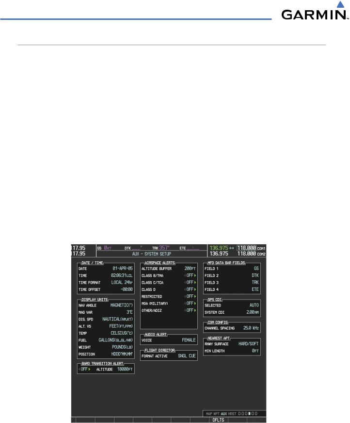
In the Auxiliary (AUX) Page Group, there are two system pages: System Setup (page 4 of 6) and System Status (page 6 of 6). The System Setup Page allows management of various system parameters, while the System Status Page displays the status of all G1000 system LRUs.
SYSTEM SETUP PAGE
The System Setup Page allows management of the following system parameters:
•Time display format (local or UTC )
•Displayed measurement units
•Baro transition alert (see Flight Instruments Section)
•Airspace alerts
•Audio alert voice
Selecting the System Setup Page:
•Flightdirectorformat(onlythesinglequeoption is available in the Cessna Nav III)
•MFD Data Bar (Navigation Status Box) fields
•GPS Course Deviation Indicator (CDI) range
•COM transceiver channel spacing
•Displayed nearest airports
1)Turn the large FMS Knob to select the AUX Page group.
2)Turn the small FMS Knob to display the System Setup Page.
Figure 1-29 System Setup Page
1-32 |
Garmin G1000 Pilot’s Guide for Cessna Nav III |
190-00498-03 Rev.A |

SYSTEM OVERVIEW
DATE/TIME
The Date/Time Box on the System Setup Page displays the current date and time and allows the pilot to set the time format (local 12-hr, local 24-hr, or UTC) and offset. The time offset is used to define current local time. UTC (also called GMT or Zulu) date and time are calculated directly from the GPS satellites signals and cannot be changed. When using a local time format, designate the offset by adding or subtracting the desired number of hours.
Set the system time format:
1)While on the System Setup Page, press the FMS Knob momentarily to activate the flashing cursor.
2)Turn the large FMS Knob to highlight the time format field in the Date/Time Box.
3)Turn the small FMS Knob to select the desired system time format (local 12hr, local 24hr, UTC) and press the ENT Key.
Set the current time offset:
1)While on the System Setup Page, press the FMS Knob momentarily to activate the flashing cursor.
2)Turn the large FMS Knob to highlight the time offset field in the Date/Time Box.
3)Turn the FMS Knobs to enter the time offset and press the ENT Key.
DISPLAY UNITS
The Display Units Box on the System Setup Page allows configuration of the measurement units used for the following displayed data:
• Nav angle (auto, true)
When set to ‘AUTO’, magnetic variation is figured into the displayed value. When ‘TRUE’ is selected, no magnetic variation is calculated and a ‘T’ is displayed next to the value.
Affects the BRG field in the PFD Navigation Status Box.
Affects Current Heading, Selected Heading, and Selected Course boxes on the PFD. Affects the BRG, DTK, TKE, TRK, and XTK fields in the MFD Navigation Status Box.
• Distance and speed (metric, nautical)
Affects the DIS field in the PFD Navigation Status Box and the range setting of the Inset Map.
Affects all distance and speed displays on the MFD with the exception of the displayed wind speed displayed on the Navigation Map Page. Wind speed is affected on the Trip Planning Page.
• Altitude and vertical speed (feet, meters)
Affects all altitude and elevation displays on the MFD, with the exception of VNAV altitudes on the Active Flight Plan Page.
• Barometric pressure (inches of mercury, hectopascals)
Affects the altimeter setting on the PFD and the pressure display on the Trip Planning Page.
190-00498-03 Rev.A |
Garmin G1000 Pilot’s Guide for Cessna Nav III |
1-33 |

SYSTEM OVERVIEW
• Temperature (Celsius, Fahrenheit)
Affects all temperature displays on the PFD.
Affects the temperature display on the Trip Planning Page. Does not affect the Engine Indicating System display.
• Fuel and fuel flow (pounds, kilograms)
Affects fuel and fuel flow displayed on the Trip Planning Page.
• Weight (pounds, kilograms)
Affects aircraft weights on the Weight Planning Page.
• Position (HDDD°MM.MM’,HDDD°MM’SS.S”) Affects all position displays.
Change a Display Units setting:
1)While on the System Setup Page, press the FMS Knob momentarily to activate the flashing cursor.
2)Turn the large FMS Knob to highlight the desired field in the Display Units Box.
3)Turn the small FMS Knob to select from a list of measurement units and press the ENT Key when the desired unit is highlighted. Press the CLR Key to cancel the action without changing the units.
AIRSPACE ALERTS
The Airspace Alerts Box allows the pilot to turn the controlled/special-use airspace message alerts on or off. This does not affect the alerts listed on the Nearest Airspaces Page or the airspace boundaries depicted on the MFD Navigation Map Page. It simply turns on/off the warning provided when the aircraft is approaching or near an airspace.
Alerts for the following airspaces can be turned on/off in the Airspace Alerts Box:
• Class B/TMA |
• Restricted |
• Class C/TCA |
• MOA (Military) |
• Class D |
• Other airspaces |
An altitude buffer is also provided which “expands” the vertical range above or below an airspace. For example, if the buffer is set at 500 feet, and the aircraft is more than 500 feet above/below an airspace, an alert message is not generated, but if the aircraft is less than 500 feet above/below an airspace and projected to enter it, the pilot is notified with an alert message. The default setting for the altitude buffer is 200 feet.
Change the altitude buffer distance setting:
1)While on the System Setup Page, press the FMS Knob momentarily to activate the flashing cursor.
2)Turn the large FMS Knob to highlight the altitude buffer field in the Airspace Alerts Box.
3)Turn the FMS Knobs to enter an altitude buffer value and press the ENT Key.
1-34 |
Garmin G1000 Pilot’s Guide for Cessna Nav III |
190-00498-03 Rev.A |

SYSTEM OVERVIEW
To turn an airspace alert on or off:
1)While on the System Setup Page, press the FMS Knob momentarily to activate the flashing cursor.
2)Turn the large FMS Knob to highlight the desired field in the Airspace Alerts Box.
3)Turn the small FMS Knob clockwise to turn the airspace alert ON or counterclockwise to turn the alert OFF.
AUDIO ALERTS
The Audio Alert Box on the System Setup Page allows the audio alert voice to be set to male or female.
To change the audio alert voice:
1)While on the System Setup Page, press the FMS Knob momentarily to activate the flashing cursor.
2)Turn the large FMS Knob to highlight the voice in the Audio Alert Box.
3)Turn the small FMS Knob to display and highlight the desired voice and press the ENT Key.
MFD DATA BAR FIELDS
The MFD Data Bar Fields Box on the System Setup Page displays the current configuration of the MFD Navigation Status Box. By default, the Navigation Status Bar is set to display ground speed (GS), distance to next waypoint (DIS), estimated time enroute (ETE), and enroute safe altitude (ESA).
Change the information shown in an MFD Navigation Status Bar field:
1)While on the System Setup Page, press the FMS Knob momentarily to activate the flashing cursor.
2)Turn the large FMS Knob to highlight the desired field number in the MFD Data Bar Fields Box.
3)Turn the small FMS Knob to display and scroll through the data options list and press the ENT Key when the desired data selection is highlighted.
The following data may be selected for display in each of the four fields of the Navigation Status Box.
• Bearing (BRG) |
• Minimum Safe Altitude (MSA) |
• Distance (DIS) |
• True Air Speed (TAS) |
• Desired Track (DTK) |
• Track Angle Error (TKE) |
• En Route Safe Altitude (ESA) |
• Track (TRK) |
• Estimated Time of Arrival (ETA) |
• Vertical Speed Required (VSR) |
• Estimated Time En Route (ETE) |
• Crosstrack Error (XTK) |
• Ground Speed (GS) |
|
GPS CDI
The GPS CDI Box on the System Setup Page allows the pilot to define the range for the on-screen course deviation indicator (CDI). The range values represent full range deflection for the CDI to either side. The default setting is ‘AUTO’. Refer to the Flight Instruments sections for a discussion on CDI scaling.
190-00498-03 Rev.A |
Garmin G1000 Pilot’s Guide for Cessna Nav III |
1-35 |

SYSTEM OVERVIEW
If a lower CDI range setting is selected (i.e., 1.0 or 0.3 nm), the higher range settings are not selected during any phase of flight. For example, if 1.0 nm is selected, the G1000 uses this for en route and terminal phases and ramps down to the proper scaling during an approach.
The GPS CDI Box on the System Setup Page displays the following:
•Selected CDI range (auto, 2 nm, 1 nm, 0.3 nm)
•Current system CDI range (2 nm, 1 nm, 0.3 nm)
Refer to the Course Deviation Indicator discussion in the Flight Instruments section for a more detailed discussion of CDI scaling.
Change the CDI range:
1)While on the System Setup Page, press the FMS Knob momentarily to activate the flashing cursor.
2)Turn the large FMS Knob to highlight the selected field in the GPS CDI Box.
3)Turn the small FMS Knob to display and scroll through the range list and press the ENT Key when the desired selection is highlighted.
COM CONFIGURATION
 NOTE: 8.33 kHzVHF communication frequency channel spacing is not approved for use in the United States. Select the 25.0 kHz channel spacing option for use in the United States.
The COM Configuration Box on the System Setup Page allows the pilot to select 8.33 kHz or 25.0 kHz COM frequency channel spacing.
Change COM channel spacing:
1)While on the System Setup Page, press the FMS Knob momentarily to activate the flashing cursor.
2)Turn the large FMS Knob to highlight the channel spacing field in the COM Configuration Box.
3)Turn the small FMS Knob to select the desired spacing and press the ENT Key.
NEAREST AIRPORTS
The Nearest Airports Box on the System Setup Page defines the minimum runway length and surface type used when determining the nine nearest airports to display on the MFD Nearest Airports Page. A minimum runway length and/or surface type can be entered to prevent airports with small runways or runways that are not of appropriate surface from being displayed. Default settings are zero feet (or meters) for runway length and “any” for runway surface type.
1-36 |
Garmin G1000 Pilot’s Guide for Cessna Nav III |
190-00498-03 Rev.A |
SYSTEM OVERVIEW
Select nearest airport surface matching criteria (any, hard only, hard/soft, water):
1)While on the System Setup Page, press the FMS Knob momentarily to activate the flashing cursor.
2)Turn the large FMS Knob to highlight the runway surface field in the Nearest Airports Box.
3)Turn the small FMS Knob to display and scroll through the runway options (any,hard only,hard/soft,water) and press the ENT Key when the desired selection is highlighted.
Select nearest airport minimum runway length matching criteria:
1)While on the System Setup Page, press the FMS Knob momentarily to activate the flashing cursor.
2)Turn the large FMS Knob to highlight the minimum length field in the Nearest Airport Box.
3)Turn the FMS Knobs to enter the minimum runway length (zero to 99,999 feet) and press the ENT Key.
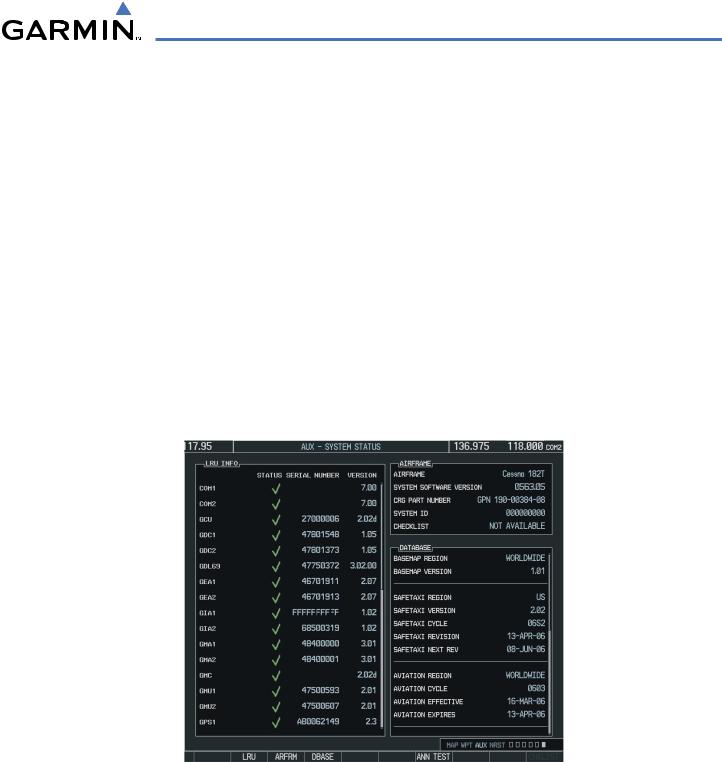
SYSTEM STATUS PAGE
The System Status Page displays the status and software version numbers for all detected system LRUs. Pertinent information on all system databases is also displayed. Active LRUs are indicated by green check marks and failed LRUs are indicated by red “X”s. Failed LRUs should be noted and a Cessna service center or Garmin dealer informed.
Figure 1-30 Example System Status Page
The LRU, ARFRM, and DBASE Softkeys on the System Status Page select the list (LRU Info, Airframe, or Database) through which the FMS Knob can be used to scroll if all the information cannot appear on the screen.
The ANN TEST Softkey, when pressed, causes an annunciation test tone to be played.
190-00498-03 Rev.A |
Garmin G1000 Pilot’s Guide for Cessna Nav III |
1-37 |
SYSTEM OVERVIEW
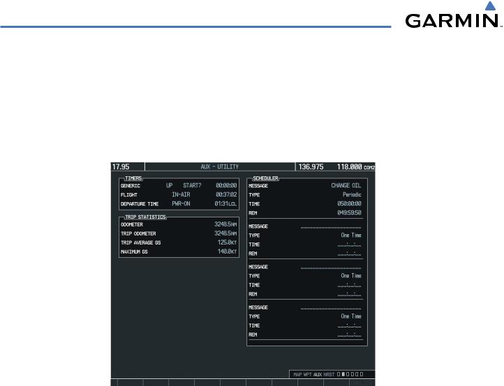
SYSTEM UTILITIES
For flight planning purposes, timers, trip statistics, and a scheduler feature are provided on the AUX - Utility Page. The timers available include a stopwatch-like generic timer, a total time in flight timer, and a record of the time of departure. Trip statistics—odometer, trip odometer, and average trip and maximum groundspeeds—are displayed from the time of the last reset. A scheduler feature is also provided so the pilot can enter reminder messages to be displayed at specified intervals in the Alerts Window on the PFD (see the Additional Features Section).
Figure 1-31 Utility Page
TIMERS
The generic timer can be set to count up or down from a specified time (HH:MM:SS). When the countdown on the timer reaches zero the digits begin to count up from zero. If the timer is reset before reaching zero on a countdown, the digits are reset to the initial value. If the timer is counting up when reset, the digits are zeroed.
Setting the generic timer:
1)Use the FMS Knob to select the AUX - Utility Page.
2)Press the FMS Knob momentarily to activate the flashing cursor.
3)Turn the small FMS Knob to select the timer counting direction (UP/DN) and press the ENT Key.
4)If a desired starting time is desired:
a)Use the large FMS Knob to highlight the HH:MM:SS field.
b)Use the FMS Knob to enter the desired time and press the ENT Key.
1-38 |
Garmin G1000 Pilot’s Guide for Cessna Nav III |
190-00498-03 Rev.A |
SYSTEM OVERVIEW
5)Turn the large FMS Knob to highlight ‘START?’ and press the ENT Key to start the timer. The field changes to ‘STOP?’.
6)To stop the timer, press the ENT Key with ‘STOP?’ highlighted. The field changes to ‘RESET?’.
7)To reset the timer, press the ENT Key with ‘RESET?’ highlighted. The field changes back to ‘START?’ and the digits are reset.
The flight timer can be set to count up from zero starting at system power-up or from the time that the aircraft lifts off; the timer can also be reset to zero at any time.
Setting the flight timer starting criterion:
1)Use the FMS Knob to select the AUX - Utility Page.
2)Press the FMS Knob momentarily to activate the flashing cursor.
3)Turn the large FMS Knob to highlight the field next to the flight timer.
4)Turn the small FMS Knob to select the starting criterion (PWR-ON or IN-AIR) and press the ENT Key.
Resetting the flight timer:
1)Use the FMS Knob to select the AUX - Utility Page.
2)Press the MENU Key.
3)With ‘Reset Flight Timer’ highlighted, press the ENT Key.
The G1000 records the time at which departure occurs, depending on whether the pilot prefers the time to be recorded from system power-up or from aircraft lift off. The displayed departure time can also be reset to display the current time at the point of reset. The format in which the time is displayed is controlled from the System Setup Page.
Setting the departure timer starting criterion:
1)Use the FMS Knob to select the AUX - Utility Page.
2)Press the FMS Knob momentarily to activate the flashing cursor.
3)Turn the large FMS Knob to highlight the field next to the departure time.
4)Turn the small FMS Knob to select the starting criterion (PWR-ON or IN-AIR) and press the ENT Key.
Resetting the departure time:
1)Use the FMS Knob to select the AUX - Utility Page.
2)Press the MENU Key.
3)Use the FMS Knob to highlight ‘Reset Departure Time’ and press the ENT Key.
TRIP STATISTICS
The odometer and trip odometer record the total mileage traveled from the last reset; these odometers can be reset independently. Resetting the trip odometer also resets the average trip groundspeed. Maximum groundspeed for the period of time since the last reset is also displayed.
190-00498-03 Rev.A |
Garmin G1000 Pilot’s Guide for Cessna Nav III |
1-39 |