

- •Section 1 System Overview
- •1.1 System Description
- •1.2 Line Replaceable Units (LRU)
- •1.3 G1000 Controls
- •PFD/MFD Controls
- •Audio Panel Controls
- •1.4 Secure Digital (SD) Cards
- •1.5 System Power-up
- •1.6 System Operation
- •Normal Display Operation
- •Reversionary Display Operation
- •AHRS Operation
- •G1000 System Annunciations
- •Softkey Function
- •GPS Receiver Operation
- •1.7 Accessing G1000 Functionality
- •Menus
- •MFD Page Groups
- •MFD System Pages
- •1.8 Display Backlighting
- •Automatic Adjustment
- •Manual Adjustment
- •Section 2 Flight Instruments
- •2.1 Flight Instruments
- •Airspeed Indicator
- •Attitude Indicator
- •Altimeter
- •Vertical Speed Indicator (VSI)
- •Vertical Deviation
- •Horizontal Situation Indicator (HSI)
- •Course Deviation Indicator (CDI)
- •2.2 Supplemental Flight Data
- •Outside Air Temperature
- •Wind Data
- •Vertical Navigation (VNV) Indications
- •2.3 PFD Annunciations and Alerting Functions
- •G1000 System Alerting
- •Marker Beacon Annunciations
- •Traffic Annunciation
- •TAWS Annunciations
- •Altitude Alerting
- •Low Altitude Annunciation
- •Minimum Descent Altitude/Decision Height Alerting
- •2.4 Abnormal Operations
- •Abnormal GPS Conditions
- •Unusual Attitudes
- •Section 3 Engine Indication System (EIS)
- •3.1 Engine Display
- •3.2 Lean Display
- •Normally-aspirated Aircraft
- •Turbocharged Aircraft
- •3.3 System Display
- •Section 4 audio panel and CNS
- •4.1 Overview
- •MFD/PFD Controls and Frequency Display
- •Audio Panel Controls
- •4.2 COM Operation
- •COM Transceiver Selection and Activation
- •COM Transceiver Manual Tuning
- •Quick-Tuning and Activating 121.500 MHz
- •Auto-tuning the COM Frequency
- •Frequency Spacing
- •Automatic Squelch
- •Volume
- •4.3 NAV Operation
- •NAV Radio Selection and Activation
- •NAV Receiver Manual Tuning
- •Auto-tuning a NAV Frequency from the MFD
- •Marker Beacon Receiver
- •DME Tuning (Optional)
- •4.4 GTX 33 Mode S Transponder
- •Transponder Controls
- •Transponder Mode Selection
- •Entering a Transponder Code
- •IDENT Function
- •Flight ID Reporting
- •4.5 Additional Audio Panel Functions
- •Power-Up
- •Mono/Stereo Headsets
- •Speaker
- •Intercom
- •Passenger Address (PA) System
- •Clearance Recorder and Player
- •Entertainment Inputs
- •4.6 Audio Panel Preflight Procedure
- •4.7 Abnormal Operation
- •Stuck Microphone
- •COM Tuning Failure
- •Audio Panel Fail-Safe Operation
- •Reversionary Mode
- •Section 5 Flight Management
- •5.1 Introduction
- •Navigation Status Box
- •5.2 Using Map Displays
- •Map Orientation
- •Map Range
- •Map Panning
- •Measuring Bearing and Distance
- •Topography
- •Map Symbols
- •Airways
- •Track Vector
- •Wind Vector
- •Nav Range Ring
- •Fuel Range Ring
- •5.3 Waypoints
- •Airports
- •Intersections
- •NDBs
- •VORs
- •User Waypoints
- •5.4 Airspaces
- •5.5 Direct-to-Navigation
- •5.6 Flight Planning
- •Flight Plan Creation
- •Adding Waypoints To An Existing Flight Plan
- •Adding Airways to a Flight Plan
- •Adding Procedures To A Stored Flight Plan
- •Flight Plan Storage
- •Flight Plan Editing
- •Along Track Offsets
- •Parallel Track
- •Activating a Flight Plan Leg
- •Inverting a Flight Plan
- •Flight Plan Views
- •Closest Point of FPL
- •5.7 Vertical Navigation
- •Altitude Constraints
- •5.8 Procedures
- •Departures
- •Arrivals
- •Approaches
- •5.9 Trip Planning
- •Trip Planning
- •5.10 RAIM Prediction
- •5.11 Navigating a Flight Plan
- •5.12 Abnormal Operation
- •Section 6 Hazard Avoidance
- •6.1 XM Satellite Weather
- •Activating Services
- •Using XM Satellite Weather Products
- •6.2 WX-500 Stormscope (Optional)
- •Setting Up Stormscope on the Navigation Map
- •Selecting the Stormscope Page
- •6.3 Terrain Proximity
- •Displaying Terrain Proximity Data
- •Terrain Proximity Page
- •6.4 TAWs (Optional)
- •Displaying TAWS Data
- •TAWS Page
- •TAWS Alerts
- •System Status
- •6.5 Traffic Information Service (TIS)
- •Displaying TRAFFIC Data
- •Traffic Map Page
- •TIS Alerts
- •System Status
- •6.6 Traffic Advisory System (TAS) (Optional)
- •TAS Symbology
- •Operation
- •Altitude Display
- •Traffic Map Page Display Range
- •TAS Alerts
- •System Status
- •6.7 ADS-B Traffic (Optional)
- •Section 7 Automatic Flight Control System
- •7.2 Flight Director Operation
- •Activating the Flight Director
- •AFCS Status Box
- •Command Bars
- •Flight Director Modes
- •7.3 Vertical Modes
- •Pitch Hold Mode (PIT)
- •Selected Altitude capture Mode (ALTs)
- •Altitude hold mode (alt)
- •Vertical Speed Mode (VS)
- •Flight Level Change Mode (FLC)
- •Vertical Navigation Modes (VPTH, ALTV)
- •Glidepath Mode (GP) (waas only)
- •Glideslope Mode (GS)
- •Go Around (GA) Mode
- •7.4 Lateral Modes
- •Roll Hold Mode (ROL)
- •Heading Select Mode (HDG)
- •Navigation mode (GPS, VOR, LOC)
- •Approach mode (GPS, VAPP, LOC)
- •Backcourse Mode (BC)
- •7.5 Autopilot Operation
- •Engaging the Autopilot
- •Control Wheel Steering
- •Disengaging the Autopilot
- •7.6 Example Procedures
- •Departure
- •Intercepting a VOR Radial
- •Flying a Flight Plan/GPS Course
- •Descent
- •Approach
- •Go Around/Missed Approach
- •7.7 AFCS Annunciations and Alerts
- •AFCS Status Alerts
- •Overspeed Protection
- •Section 8 Additional Features
- •8.1 SafeTaxi
- •SafeTaxi Cycle Number and Revision
- •8.2 ChartView
- •ChartView Softkeys
- •Terminal Procedures Charts
- •Chart Options
- •Day/Night View
- •ChartView Cycle Number and Expiration Date
- •8.3 FliteCharts
- •FliteCharts Softkeys
- •Terminal Procedures Charts
- •Chart Options
- •Day/Night View
- •FliteCharts Cycle Number and Expiration Date
- •8.4 XM Radio Entertainment (Optional)
- •Activating XM Satellite Radio Services
- •Using XM Radio
- •Automatic Audio Muting
- •8.5 Scheduler
- •8.5 Abnormal Operation
- •Annunciations and Alerts
- •Alert Level Definitions
- •Nav III Aircraft Alerts
- •CO Guardian Messages
- •G1000 System Annunciations
- •Other G1000 Aural Alerts
- •G1000 System Message Advisories
- •AFCS Alerts
- •TAWS ALERTS
- •TAWS System Status Annunciations
- •SD Card Use
- •Jeppesen Databases
- •Garmin Databases
- •Glossary
- •Frequently Asked Questions
- •General TIS Information
- •Introduction
- •TIS vs. TAS/TCAS
- •TIS Limitations
- •Map Symbols
- •Index
HAZARD AVOIDANCE
6.4 TAWS (OPTIONAL)
WARNING: Do not use TAWS information for primary terrain avoidance. TAWS is intended only to enhance situational awareness.
NOTE: The data contained in the TAWS databases comes from government agencies. Garmin accurately processes and cross-validates the data but cannot guarantee the accuracy and completeness of the data.
TAWS (Terrain Awareness and Warning System) is an optional feature to increase situational awareness and aid in reducing controlled flight into terrain (CFIT). TAWS provides visual and aural annunciations when terrain and obstacles are within the given altitude threshold from the aircraft. The displayed alerts and warnings are advisory in nature only.
TAWS satisfies TSO-C151b Class B requirements for certification. Class B TAWS is required for all Part 91 aircraft operations with six or more passenger seats and for Part 135 turbine aircraft operations with six to nine passenger seats (FAR Parts 91.223, 135.154).
TAWS requires the following to operate properly:
•A valid terrain/obstacle/airport terrain database
•A valid 3-D GPS position solution
TAWS uses terrain and obstacle information supplied by government sources. Terrain information is based on terrain elevation information in a database that may contain inaccuracies. Individual obstructions may be shown if available in the database. The data undergoes verification by Garmin to confirm accuracy of the content, per TSO-C151b. However, the displayed information should never be understood as being all-inclusive and data may be inaccurate.
TAWS uses information provided from the GPS receiver to provide a horizontal position and altitude. GPS altitude is derived from satellite measurements. GPS altitude is converted to a mean sea level (MSL)-based altitude (GPS-MSL altitude) and is used to determine TAWS alerts. GPS-MSL altitude accuracy is affected by factors such as satellite geometry, but it is not subject to variations in pressure and temperature that normally affect pressure altitude devices. GPS-MSL altitude does not require local altimeter settings to determine MSL altitude. Therefore, GPS altitude provides a highly accurate and reliable MSL altitude source to calculate terrain and obstacle alerts.
The terrain and obstacle databases used by TAWS are referenced to mean sea level (MSL). Using the GPS position and GPS-MSL altitude, TAWS displays a 2-D picture of the surrounding terrain and obstacles relative to the position and altitude of the aircraft. Furthermore, the GPS position and GPS-MSL altitude are used to calculate and “predict” the aircraft’s flight path in relation to the surrounding terrain and obstacles. In this manner, TAWS can provide advanced alerts of predicted dangerous terrain conditions.
Baro-corrected altitude (or indicated altitude) is derived by adjusting the altimeter setting for local atmospheric conditions. Themostaccuratebaro-correctedaltitudecanbeachievedbyfrequentlyupdatingthealtimetersetting to the nearest reporting station along the flight path. However, because actual atmosphere conditions seldom match the standard conditions defined by the International Standard Atmosphere (ISA) model (where pressure, temperature, and lapse rates have fixed values), it is common for the baro-corrected altitude (as read from the altimeter) to differ from the GPS-MSL altitude. This variation results in the aircraft’s true altitude differing from the baro-corrected altitude.
6-36 |
Garmin G1000 Pilot’s Guide for Cessna Nav III |
190-00498-03 Rev.A |
HAZARD AVOIDANCE
DISPLAYING TAWS DATA
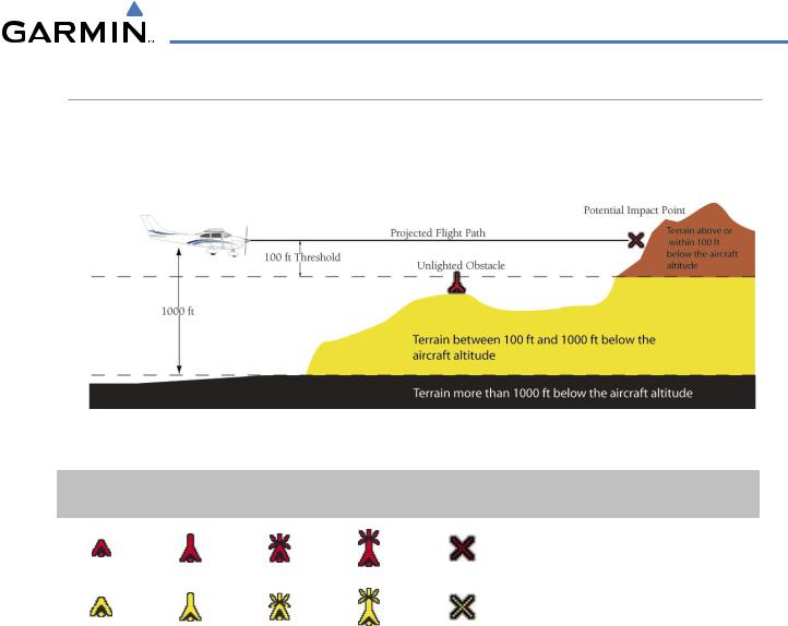
TAWS uses yellow (caution) and red (warning) to depict terrain and obstacles (with heights greater than 200 feet above ground level, AGL) alerts relative to aircraft altitude. Colors are adjusted automatically as the aircraft altitude changes. The colors and symbols in Figure 6-51 and Table 6-5 are used to represent terrain, obstacles, and potential impact points.
Figure 6-51 Terrain Altitude/Color Correlation for TAWS
Unlighted Obstacle |
Lighted Obstacle |
Potential |
Obstacle Location |
|||
< 1000’ AGL |
> 1000’ AGL |
< 1000’ AGL |
> 1000’ AGL |
Impact Points |
||
|
||||||
|
|
|
|
|
WARNING: Red obstacle is above or within |
|
|
|
|
|
|
100’ below current aircraft altitude |
|
|
|
|
|
|
|
|
|
|
|
|
|
CAUTION:Yellow obstacle is between 100’ |
|
|
|
|
|
|
and 1000’ below current aircraft altitude |
|
|
|
|
|
|
|
|
Table 6-5 TAWS Obstacle Colors and Symbology
TAWS information can be displayed on the following maps:
• PFD Inset Map |
• Trip Planning Page |
• Navigation Map Page |
• Flight Plan Pages |
• TAWS Page |
|
Displaying terrain and obstacle information (maps other than the TAWS Page):
1)Press the MAP Softkey (for the PFD Inset Map, press the INSET Softkey).
2)Press the TERRAIN Softkey to display terrain and obstacle data.
When TAWS is selected on maps other than the TAWS Page, an icon to indicate the feature is enabled for display and a legend for TAWS terrain colors are shown (Figure 6-58).
The Navigation Map Page Setup Menu provides a means in addition to the softkey for enabling/disabling display of terrain and obstacles. The setup menu also controls the map range settings above which terrain and obstacle data are decluttered from the display. If a map range larger than the map range setting is selected, the data is removed from the map.
190-00498-03 Rev.A |
Garmin G1000 Pilot’s Guide for Cessna Nav III |
6-37 |
HAZARD AVOIDANCE
Terrain data can be selected for display independently of obstacle data; however, obstacles for which warnings and cautions are issued are shown when terrain is selected for display and the map range is within the setting limit.
MapsbesidestheTAWSPageusesettingsbasedonthoseselectedfortheNavigationMapPage. Themaximum display ranges for obstacles on each map are dependent on the range setting made for the Navigation Map. If the maximum range for obstacle display on the Navigation Map is adjusted to below 20 nm, the highest obstacle display range settings on the other applicable maps are also adjusted proportionally.
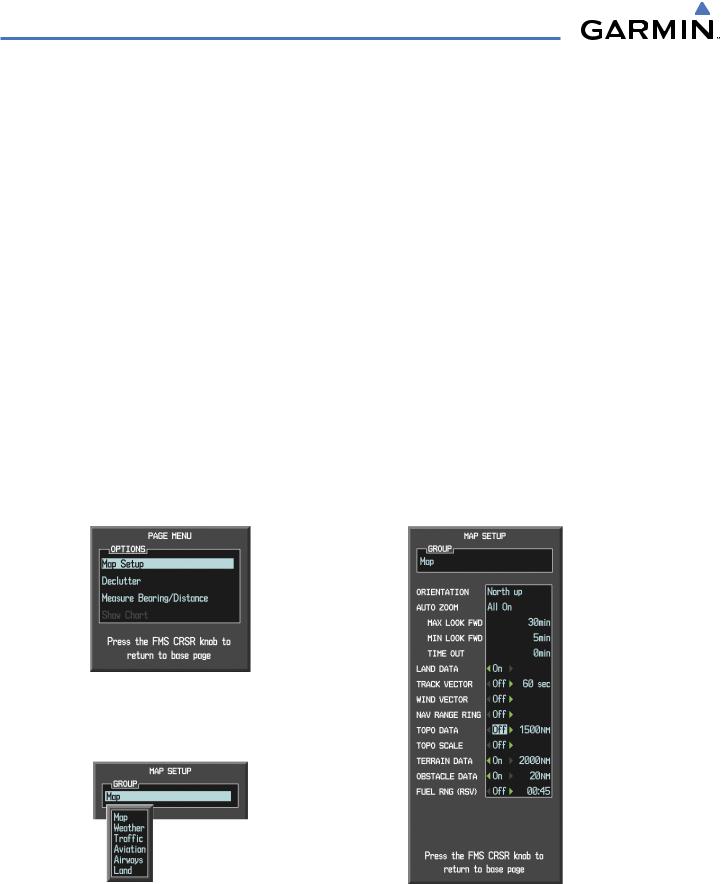
Customizing terrain and obstacle display on the Navigation Map Page:
1)Select the Navigation Map Page.
2)Press the MENU Key.
3)With ‘Map Setup’ highlighted, press the ENT Key (Figure 6-52).
4)Turn the small FMS Knob to select the ‘Map’ Group and press the ENT Key (Figure 6-53).
5)Turn the large FMS Knob or press the ENT Key to scroll though product selections (Figure 6-54).
•TERRAIN DATA – Turns the display of terrain data on or off and sets maximum range at which terrain is shown
•OBSTACLE DATA – Turns the display of obstacle data on or off and sets maximum range at which obstacles are shown
6)Turn the small FMS Knob to scroll though options for each product (ON/OFF, range settings).
7)Press the ENT Key to select an option.
8)Press the FMS Knob or CLR Key to return to the Navigation Map Page with the changed settings.
Figure 6-52 Navigation Map Page Menu
Figure 6-53 Navigation Map Page Setup Menu |
Figure 6-54 Navigation Map Page Setup Menu, Map Group |
6-38 |
Garmin G1000 Pilot’s Guide for Cessna Nav III |
190-00498-03 Rev.A |

HAZARD AVOIDANCE
TAWS PAGE
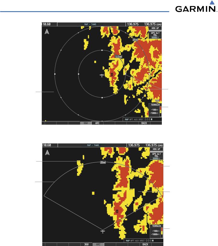
The TAWS Page is specialized to show terrain, obstacle, and potential impact point data in relation to the aircraft’s current altitude, without clutter from the basemap. Aviation data (airports, VORs, and other NAVAIDs) can be displayed for reference. If an obstacle and the projected flight path of the aircraft intersect, the display automatically zooms in to the closest potential point of impact on the TAWS Page.
Aircraft orientation on this map is always heading up unless there is no valid heading. Two views are available relative to the position of the aircraft: the 360° default display and the radar-like ARC (120°) display. Map range is adjustable with the RANGE Knob from 1 to 200 nm, as indicated by the map range rings (or arcs).
Displaying the TAWS Page:
1)Turn the large FMS Knob to select the Map Page Group.
2)Turn the small FMS Knob to select TAWS Page.
Changing the TAWS Page view:
1)Press the VIEW Softkey.
2)Press the 360 or ARC Softkey to select the desired view.
Or:
1)Press the MENU Key.
2)Select ‘View 120º’ or ‘View 360º’ (choice dependent on current state) and press the ENT Key to change the view
Showing/hiding aviation information on the TAWS Page:
1)Press the MENU Key.
2)Select ‘Show Aviation Data’ or ‘Hide Aviation Data’ (choice dependent on current state) and press the ENT Key.
190-00498-03 Rev.A |
Garmin G1000 Pilot’s Guide for Cessna Nav III |
6-39 |
HAZARD AVOIDANCE
Yellow Terrain |
Red Terrain |
|||
(Caution - Terrain |
(Warning - Terrain Above |
|||
Between 100’ and |
|
|
|
|
or Within 100’ Below |
||||
1000’ Below the |
the Aircraft Altitude) |
|||
Aircraft Altitude) |
|
|
||
Black Terrain
(Terrain More than Map Range Rings 1000’ Below the
Aircraft Altitude)
Terrain Legend
Figure 6-55 TAWS Page
Yellow Terrain
(Caution - Terrain
Between 100’ and
1000’ Below the
Aircraft Altitude)
Map Range Arc
Red Terrain
(Warning - Terrain Above or Within 100’ Below the Aircraft Altitude)
Black Terrain
(Terrain More than 1000’ Below the Aircraft Altitude)
Terrain Legend
Figure 6-56 TAWS Page (ARC View)
6-40 |
Garmin G1000 Pilot’s Guide for Cessna Nav III |
190-00498-03 Rev.A |