

- •Section 1 System Overview
- •1.1 System Description
- •1.2 Line Replaceable Units (LRU)
- •1.3 G1000 Controls
- •PFD/MFD Controls
- •Audio Panel Controls
- •1.4 Secure Digital (SD) Cards
- •1.5 System Power-up
- •1.6 System Operation
- •Normal Display Operation
- •Reversionary Display Operation
- •AHRS Operation
- •G1000 System Annunciations
- •Softkey Function
- •GPS Receiver Operation
- •1.7 Accessing G1000 Functionality
- •Menus
- •MFD Page Groups
- •MFD System Pages
- •1.8 Display Backlighting
- •Automatic Adjustment
- •Manual Adjustment
- •Section 2 Flight Instruments
- •2.1 Flight Instruments
- •Airspeed Indicator
- •Attitude Indicator
- •Altimeter
- •Vertical Speed Indicator (VSI)
- •Vertical Deviation
- •Horizontal Situation Indicator (HSI)
- •Course Deviation Indicator (CDI)
- •2.2 Supplemental Flight Data
- •Outside Air Temperature
- •Wind Data
- •Vertical Navigation (VNV) Indications
- •2.3 PFD Annunciations and Alerting Functions
- •G1000 System Alerting
- •Marker Beacon Annunciations
- •Traffic Annunciation
- •TAWS Annunciations
- •Altitude Alerting
- •Low Altitude Annunciation
- •Minimum Descent Altitude/Decision Height Alerting
- •2.4 Abnormal Operations
- •Abnormal GPS Conditions
- •Unusual Attitudes
- •Section 3 Engine Indication System (EIS)
- •3.1 Engine Display
- •3.2 Lean Display
- •Normally-aspirated Aircraft
- •Turbocharged Aircraft
- •3.3 System Display
- •Section 4 audio panel and CNS
- •4.1 Overview
- •MFD/PFD Controls and Frequency Display
- •Audio Panel Controls
- •4.2 COM Operation
- •COM Transceiver Selection and Activation
- •COM Transceiver Manual Tuning
- •Quick-Tuning and Activating 121.500 MHz
- •Auto-tuning the COM Frequency
- •Frequency Spacing
- •Automatic Squelch
- •Volume
- •4.3 NAV Operation
- •NAV Radio Selection and Activation
- •NAV Receiver Manual Tuning
- •Auto-tuning a NAV Frequency from the MFD
- •Marker Beacon Receiver
- •DME Tuning (Optional)
- •4.4 GTX 33 Mode S Transponder
- •Transponder Controls
- •Transponder Mode Selection
- •Entering a Transponder Code
- •IDENT Function
- •Flight ID Reporting
- •4.5 Additional Audio Panel Functions
- •Power-Up
- •Mono/Stereo Headsets
- •Speaker
- •Intercom
- •Passenger Address (PA) System
- •Clearance Recorder and Player
- •Entertainment Inputs
- •4.6 Audio Panel Preflight Procedure
- •4.7 Abnormal Operation
- •Stuck Microphone
- •COM Tuning Failure
- •Audio Panel Fail-Safe Operation
- •Reversionary Mode
- •Section 5 Flight Management
- •5.1 Introduction
- •Navigation Status Box
- •5.2 Using Map Displays
- •Map Orientation
- •Map Range
- •Map Panning
- •Measuring Bearing and Distance
- •Topography
- •Map Symbols
- •Airways
- •Track Vector
- •Wind Vector
- •Nav Range Ring
- •Fuel Range Ring
- •5.3 Waypoints
- •Airports
- •Intersections
- •NDBs
- •VORs
- •User Waypoints
- •5.4 Airspaces
- •5.5 Direct-to-Navigation
- •5.6 Flight Planning
- •Flight Plan Creation
- •Adding Waypoints To An Existing Flight Plan
- •Adding Airways to a Flight Plan
- •Adding Procedures To A Stored Flight Plan
- •Flight Plan Storage
- •Flight Plan Editing
- •Along Track Offsets
- •Parallel Track
- •Activating a Flight Plan Leg
- •Inverting a Flight Plan
- •Flight Plan Views
- •Closest Point of FPL
- •5.7 Vertical Navigation
- •Altitude Constraints
- •5.8 Procedures
- •Departures
- •Arrivals
- •Approaches
- •5.9 Trip Planning
- •Trip Planning
- •5.10 RAIM Prediction
- •5.11 Navigating a Flight Plan
- •5.12 Abnormal Operation
- •Section 6 Hazard Avoidance
- •6.1 XM Satellite Weather
- •Activating Services
- •Using XM Satellite Weather Products
- •6.2 WX-500 Stormscope (Optional)
- •Setting Up Stormscope on the Navigation Map
- •Selecting the Stormscope Page
- •6.3 Terrain Proximity
- •Displaying Terrain Proximity Data
- •Terrain Proximity Page
- •6.4 TAWs (Optional)
- •Displaying TAWS Data
- •TAWS Page
- •TAWS Alerts
- •System Status
- •6.5 Traffic Information Service (TIS)
- •Displaying TRAFFIC Data
- •Traffic Map Page
- •TIS Alerts
- •System Status
- •6.6 Traffic Advisory System (TAS) (Optional)
- •TAS Symbology
- •Operation
- •Altitude Display
- •Traffic Map Page Display Range
- •TAS Alerts
- •System Status
- •6.7 ADS-B Traffic (Optional)
- •Section 7 Automatic Flight Control System
- •7.2 Flight Director Operation
- •Activating the Flight Director
- •AFCS Status Box
- •Command Bars
- •Flight Director Modes
- •7.3 Vertical Modes
- •Pitch Hold Mode (PIT)
- •Selected Altitude capture Mode (ALTs)
- •Altitude hold mode (alt)
- •Vertical Speed Mode (VS)
- •Flight Level Change Mode (FLC)
- •Vertical Navigation Modes (VPTH, ALTV)
- •Glidepath Mode (GP) (waas only)
- •Glideslope Mode (GS)
- •Go Around (GA) Mode
- •7.4 Lateral Modes
- •Roll Hold Mode (ROL)
- •Heading Select Mode (HDG)
- •Navigation mode (GPS, VOR, LOC)
- •Approach mode (GPS, VAPP, LOC)
- •Backcourse Mode (BC)
- •7.5 Autopilot Operation
- •Engaging the Autopilot
- •Control Wheel Steering
- •Disengaging the Autopilot
- •7.6 Example Procedures
- •Departure
- •Intercepting a VOR Radial
- •Flying a Flight Plan/GPS Course
- •Descent
- •Approach
- •Go Around/Missed Approach
- •7.7 AFCS Annunciations and Alerts
- •AFCS Status Alerts
- •Overspeed Protection
- •Section 8 Additional Features
- •8.1 SafeTaxi
- •SafeTaxi Cycle Number and Revision
- •8.2 ChartView
- •ChartView Softkeys
- •Terminal Procedures Charts
- •Chart Options
- •Day/Night View
- •ChartView Cycle Number and Expiration Date
- •8.3 FliteCharts
- •FliteCharts Softkeys
- •Terminal Procedures Charts
- •Chart Options
- •Day/Night View
- •FliteCharts Cycle Number and Expiration Date
- •8.4 XM Radio Entertainment (Optional)
- •Activating XM Satellite Radio Services
- •Using XM Radio
- •Automatic Audio Muting
- •8.5 Scheduler
- •8.5 Abnormal Operation
- •Annunciations and Alerts
- •Alert Level Definitions
- •Nav III Aircraft Alerts
- •CO Guardian Messages
- •G1000 System Annunciations
- •Other G1000 Aural Alerts
- •G1000 System Message Advisories
- •AFCS Alerts
- •TAWS ALERTS
- •TAWS System Status Annunciations
- •SD Card Use
- •Jeppesen Databases
- •Garmin Databases
- •Glossary
- •Frequently Asked Questions
- •General TIS Information
- •Introduction
- •TIS vs. TAS/TCAS
- •TIS Limitations
- •Map Symbols
- •Index
ADDITIONAL FEATURES
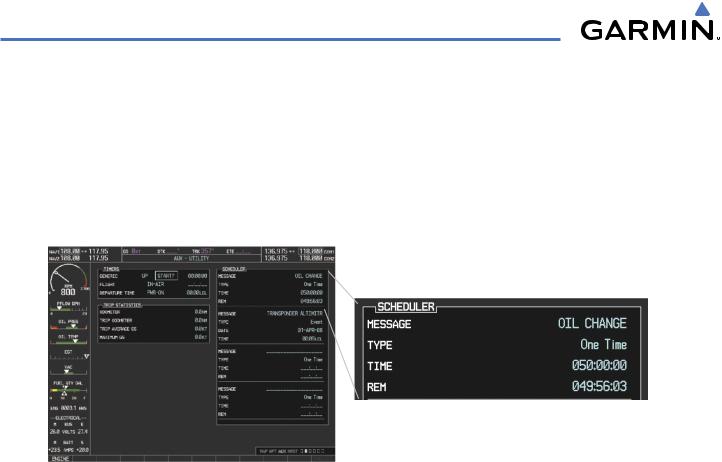
8.5 SCHEDULER
The Scheduler feature can be used to enter and display reminder messages (e.g., Change oil, Switch fuel tanks, or Altimeter-Transponder Check) in the Alerts Window on the PFD. Messages can be set to display based on a specific date and time (event), once the message timer reaches zero (one-time; default setting), or recurrently whenever the message timer reaches zero (periodic). Message timers set to periodic alerting automatically reset to the original timer value once the message is displayed. When power is cycled, messages are retained until deleted, and message timer countdown is restarted.
Figure 8-64 Scheduler (Utility Page)
Entering a scheduler message:
1)Select the AUX - Utility Page.
2)Press the FMS Knob momentarily to activate the flashing cursor.
3)Turn the large FMS Knob to highlight the first empty scheduler message naming field.
4)Use the FMS Knob to enter the message text to be displayed in the Alerts Window and press the ENT Key.
5)Press the ENT Key again or use the large FMS Knob to move the cursor to the field next to Type.
6)Turn the small FMS Knob to select the message alert type:
•Event—Message issued at the specified date/time
•One-time—Message issued when the message timer reaches zero (default setting)
•Periodic—Message issued each time the message timer reaches zero
7)Press the ENT Key again or use the large FMS Knob to move the cursor to the next field.
8)For periodic and one-time message, use the FMS Knob to enter the timer value (HH:MM:SS) from which to countdown and press the ENT Key.
8-56 |
Garmin G1000 Pilot’s Guide for Cessna Nav III |
190-00498-03 Rev A |
ADDITIONAL FEATURES
9)For event-based messages:
a)Use the FMS Knob to enter the desired date (DD-MM-YY) and press the ENT Key.
b)Press the ENT Key again or use the large FMS Knob to move the cursor to the next field.
c)Use the FMS Knob to enter the desired time (HH:MM) and press the ENT Key.
10)Press the ENT Key again or use the large FMS Knob to move the cursor to enter the next message.
Deleting a scheduler message:
1)Select the AUX - Utility Page.
2)Press the FMS Knob momentarily to activate the flashing cursor.
3)Turn the large FMS Knob to highlight the name field of the scheduler message to be deleted.
4)Press the CLR Key to clear the message text. If the CLR Key is pressed again, the message is restored.
5)Press the ENT Key while the message line is cleared to clear the message time.
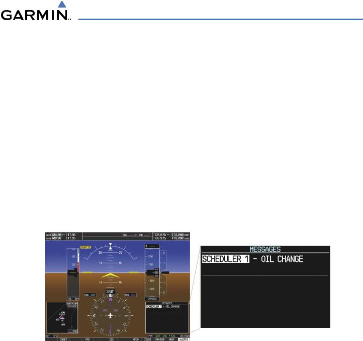
Scheduler messages appear in the Alerts Window on the PFD. When a scheduler message is waiting, the ALERTS Softkey label changes to ADVISORY. Pressing the ADVISORY Softkey opens the Alerts Window and acknowledges the scheduler message. The softkey label reverts to ALERTS when pressed, the Alerts Window is removed from the display, and the scheduler message is deleted from the message queue.
Figure 8-65 PFD Alerts Window
190-00498-03 Rev A |
Garmin G1000 Pilot’s Guide for Cessna Nav III |
8-57 |
ADDITIONAL FEATURES
8.5 ABNORMAL OPERATION
GDL 69/69A DATA LINK RECEIVER TROUBLESHOOTING
Some quick troubleshooting steps listed below can be performed to find the possible cause of a failure.
•Ensure the owner/operator of the aircraft in which the Data Link Receiver is installed has subscribed to XM
•Ensure the XM subscription has been activated
•Perform a quick check of the circuit breakers to ensure that power is applied to the Data Link Receiver
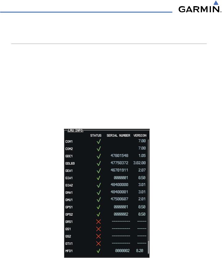
For troubleshooting purposes, check the LRU Information Box on the AUX - System Status Page for Data Link Receiver (GDL 69/69A) status, serial number, and software version number. If a failure has been detected in the GDL 69/69A the status is marked with a red X.
Selecting the System Status Page:
1)Turn the large FMS Knob to select the AUX Page Group.
2)Turn the small FMS Knob to select the System Status Page (the last page in the AUX Page Group).
Figure 8-66 LRU Information Window on System Status Page
8-58 |
Garmin G1000 Pilot’s Guide for Cessna Nav III |
190-00498-03 Rev A |

ADDITIONAL FEATURES
If a failure still exists, the following messages may provide insight as to the possible problem:
Message |
Message Location |
Description |
CHECK ANTENNA |
XM Radio Page - active channel field |
Data Link Receiver antenna error; service required |
UPDATING |
XM Radio Page - active channel field |
Data Link Receiver updating encryption code |
NO SIGNAL |
XM Radio Page - active channel field |
Loss of signal; signal strength too low for receiver |
|
Weather Datalink Page - center of page |
|
LOADING |
XM Radio Page - active channel field |
Acquiring channel audio or information |
OFF AIR |
XM Radio Page - active channel field |
Channel not in service |
--- |
XM Radio Page - active channel field |
Missing channel information |
WEATHER DATA LINK FAILURE |
Weather Datalink Page - center of page |
No communication from Data Link Receiver |
|
|
within last 5 minutes |
ACTIVATION REQUIRED |
Weather Datalink Page - center of page |
XM subscription is not activated |
Table 8-3 GDL 69/69A Data Link Receiver Error Messages
190-00498-03 Rev A |
Garmin G1000 Pilot’s Guide for Cessna Nav III |
8-59 |

ADDITIONAL FEATURES
BLANK PAGE
8-60 |
Garmin G1000 Pilot’s Guide for Cessna Nav III |
190-00498-03 Rev A |