

- •Section 1 System Overview
- •1.1 System Description
- •1.2 Line Replaceable Units (LRU)
- •1.3 G1000 Controls
- •PFD/MFD Controls
- •Audio Panel Controls
- •1.4 Secure Digital (SD) Cards
- •1.5 System Power-up
- •1.6 System Operation
- •Normal Display Operation
- •Reversionary Display Operation
- •AHRS Operation
- •G1000 System Annunciations
- •Softkey Function
- •GPS Receiver Operation
- •1.7 Accessing G1000 Functionality
- •Menus
- •MFD Page Groups
- •MFD System Pages
- •1.8 Display Backlighting
- •Automatic Adjustment
- •Manual Adjustment
- •Section 2 Flight Instruments
- •2.1 Flight Instruments
- •Airspeed Indicator
- •Attitude Indicator
- •Altimeter
- •Vertical Speed Indicator (VSI)
- •Vertical Deviation
- •Horizontal Situation Indicator (HSI)
- •Course Deviation Indicator (CDI)
- •2.2 Supplemental Flight Data
- •Outside Air Temperature
- •Wind Data
- •Vertical Navigation (VNV) Indications
- •2.3 PFD Annunciations and Alerting Functions
- •G1000 System Alerting
- •Marker Beacon Annunciations
- •Traffic Annunciation
- •TAWS Annunciations
- •Altitude Alerting
- •Low Altitude Annunciation
- •Minimum Descent Altitude/Decision Height Alerting
- •2.4 Abnormal Operations
- •Abnormal GPS Conditions
- •Unusual Attitudes
- •Section 3 Engine Indication System (EIS)
- •3.1 Engine Display
- •3.2 Lean Display
- •Normally-aspirated Aircraft
- •Turbocharged Aircraft
- •3.3 System Display
- •Section 4 audio panel and CNS
- •4.1 Overview
- •MFD/PFD Controls and Frequency Display
- •Audio Panel Controls
- •4.2 COM Operation
- •COM Transceiver Selection and Activation
- •COM Transceiver Manual Tuning
- •Quick-Tuning and Activating 121.500 MHz
- •Auto-tuning the COM Frequency
- •Frequency Spacing
- •Automatic Squelch
- •Volume
- •4.3 NAV Operation
- •NAV Radio Selection and Activation
- •NAV Receiver Manual Tuning
- •Auto-tuning a NAV Frequency from the MFD
- •Marker Beacon Receiver
- •DME Tuning (Optional)
- •4.4 GTX 33 Mode S Transponder
- •Transponder Controls
- •Transponder Mode Selection
- •Entering a Transponder Code
- •IDENT Function
- •Flight ID Reporting
- •4.5 Additional Audio Panel Functions
- •Power-Up
- •Mono/Stereo Headsets
- •Speaker
- •Intercom
- •Passenger Address (PA) System
- •Clearance Recorder and Player
- •Entertainment Inputs
- •4.6 Audio Panel Preflight Procedure
- •4.7 Abnormal Operation
- •Stuck Microphone
- •COM Tuning Failure
- •Audio Panel Fail-Safe Operation
- •Reversionary Mode
- •Section 5 Flight Management
- •5.1 Introduction
- •Navigation Status Box
- •5.2 Using Map Displays
- •Map Orientation
- •Map Range
- •Map Panning
- •Measuring Bearing and Distance
- •Topography
- •Map Symbols
- •Airways
- •Track Vector
- •Wind Vector
- •Nav Range Ring
- •Fuel Range Ring
- •5.3 Waypoints
- •Airports
- •Intersections
- •NDBs
- •VORs
- •User Waypoints
- •5.4 Airspaces
- •5.5 Direct-to-Navigation
- •5.6 Flight Planning
- •Flight Plan Creation
- •Adding Waypoints To An Existing Flight Plan
- •Adding Airways to a Flight Plan
- •Adding Procedures To A Stored Flight Plan
- •Flight Plan Storage
- •Flight Plan Editing
- •Along Track Offsets
- •Parallel Track
- •Activating a Flight Plan Leg
- •Inverting a Flight Plan
- •Flight Plan Views
- •Closest Point of FPL
- •5.7 Vertical Navigation
- •Altitude Constraints
- •5.8 Procedures
- •Departures
- •Arrivals
- •Approaches
- •5.9 Trip Planning
- •Trip Planning
- •5.10 RAIM Prediction
- •5.11 Navigating a Flight Plan
- •5.12 Abnormal Operation
- •Section 6 Hazard Avoidance
- •6.1 XM Satellite Weather
- •Activating Services
- •Using XM Satellite Weather Products
- •6.2 WX-500 Stormscope (Optional)
- •Setting Up Stormscope on the Navigation Map
- •Selecting the Stormscope Page
- •6.3 Terrain Proximity
- •Displaying Terrain Proximity Data
- •Terrain Proximity Page
- •6.4 TAWs (Optional)
- •Displaying TAWS Data
- •TAWS Page
- •TAWS Alerts
- •System Status
- •6.5 Traffic Information Service (TIS)
- •Displaying TRAFFIC Data
- •Traffic Map Page
- •TIS Alerts
- •System Status
- •6.6 Traffic Advisory System (TAS) (Optional)
- •TAS Symbology
- •Operation
- •Altitude Display
- •Traffic Map Page Display Range
- •TAS Alerts
- •System Status
- •6.7 ADS-B Traffic (Optional)
- •Section 7 Automatic Flight Control System
- •7.2 Flight Director Operation
- •Activating the Flight Director
- •AFCS Status Box
- •Command Bars
- •Flight Director Modes
- •7.3 Vertical Modes
- •Pitch Hold Mode (PIT)
- •Selected Altitude capture Mode (ALTs)
- •Altitude hold mode (alt)
- •Vertical Speed Mode (VS)
- •Flight Level Change Mode (FLC)
- •Vertical Navigation Modes (VPTH, ALTV)
- •Glidepath Mode (GP) (waas only)
- •Glideslope Mode (GS)
- •Go Around (GA) Mode
- •7.4 Lateral Modes
- •Roll Hold Mode (ROL)
- •Heading Select Mode (HDG)
- •Navigation mode (GPS, VOR, LOC)
- •Approach mode (GPS, VAPP, LOC)
- •Backcourse Mode (BC)
- •7.5 Autopilot Operation
- •Engaging the Autopilot
- •Control Wheel Steering
- •Disengaging the Autopilot
- •7.6 Example Procedures
- •Departure
- •Intercepting a VOR Radial
- •Flying a Flight Plan/GPS Course
- •Descent
- •Approach
- •Go Around/Missed Approach
- •7.7 AFCS Annunciations and Alerts
- •AFCS Status Alerts
- •Overspeed Protection
- •Section 8 Additional Features
- •8.1 SafeTaxi
- •SafeTaxi Cycle Number and Revision
- •8.2 ChartView
- •ChartView Softkeys
- •Terminal Procedures Charts
- •Chart Options
- •Day/Night View
- •ChartView Cycle Number and Expiration Date
- •8.3 FliteCharts
- •FliteCharts Softkeys
- •Terminal Procedures Charts
- •Chart Options
- •Day/Night View
- •FliteCharts Cycle Number and Expiration Date
- •8.4 XM Radio Entertainment (Optional)
- •Activating XM Satellite Radio Services
- •Using XM Radio
- •Automatic Audio Muting
- •8.5 Scheduler
- •8.5 Abnormal Operation
- •Annunciations and Alerts
- •Alert Level Definitions
- •Nav III Aircraft Alerts
- •CO Guardian Messages
- •G1000 System Annunciations
- •Other G1000 Aural Alerts
- •G1000 System Message Advisories
- •AFCS Alerts
- •TAWS ALERTS
- •TAWS System Status Annunciations
- •SD Card Use
- •Jeppesen Databases
- •Garmin Databases
- •Glossary
- •Frequently Asked Questions
- •General TIS Information
- •Introduction
- •TIS vs. TAS/TCAS
- •TIS Limitations
- •Map Symbols
- •Index
AUTOMATIC FLIGHT CONTROL SYSTEM
SECTION 7 AUTOMATIC FLIGHT CONTROL SYSTEM
 NOTE: The approved Pilot’s Operating Handbook (POH) always supersedes the information in this Pilot’s Guide.
 NOTE: A failure of the primary (#1) GIA 63/63W Integrated Avionics Unit (IAU) results in loss of the flight director. Any IAU failure results in loss of the autopilot and manual electric trim.
 NOTE: The GFC 700 is not available for the Cessna 172R.
The GFC 700 is a digital Automatic Flight Control System (AFCS), fully integrated within the G1000 System avionicsarchitecture. TheSystemOverviewsectionprovidesablockdiagramtosupportthissystemdescription. GFC 700 AFCS functionality in the Cessna NAV III aircraft is distributed across the following Line Replaceable Units (LRUs):
• GDU 1044B |
Primary Flight Display (PFD) |
• GSA 81 AFCS Servos (3) |
• GDU 1044B |
Multi-Function Display (MFD) |
• GSM 85 Servo Mounts (3) |
•GIA 63/63W Integrated Avionics Units (2)
The GFC 700 AFCS can be divided into these main operating functions:
•Flight Director (FD) — Flight director operation takes place within the primary (#1) IAU. Flight director commands are displayed on the PFD. The flight director provides:
–Command Bars showing pitch/roll guidance
–Pitch/roll mode selection and processing
–Autopilot communication
•Autopilot (AP) — Autopilot operation occurs within the pitch, roll and pitch trim servo and provides servo monitoring and automatic flight control in response to flight director steering commands, AHRS attitude and rate information, and airspeed.
•Manual Electric Trim (MET) — The pitch trim adapter provides manual electric trim capability when the autopilot is not engaged.
190-00498-03 Rev.A |
Garmin G1000 Pilot’s Guide for Cessna Nav III |
7-1 |
AUTOMATIC FLIGHT CONTROL SYSTEM
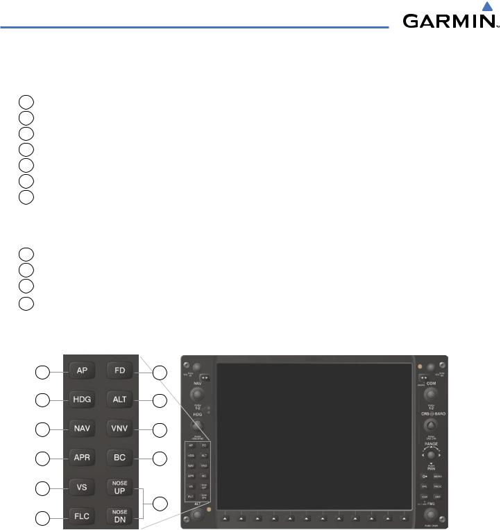
7.1 AFCS CONTROLS
The following dedicated AFCS keys are located on the bezels of the PFD and MFD:
1 |
AP Key |
Engages/disengages the autopilot |
2 |
HDG Key |
Selects/deselects Heading Select Mode |
3 |
NAV Key |
Selects/deselects Navigation Mode |
4 |
APR Key |
Selects/deselects Approach Mode |
5 |
VS Key |
Selects/deselects Vertical Speed Mode |
6 |
FLC Key |
Selects/deselects Flight Level Change Mode |
7 |
FD Key |
Activates/deactivates the flight director only |
|
|
Pressingonceturnsontheflightdirectorinthedefaultpitchandrollmodes. Pressing |
|
|
again deactivates the flight director and removes the Command Bars. If the autopilot |
|
|
is engaged, the key is disabled. |
8 |
ALT Key |
Selects/deselects Altitude Hold Mode |
9 |
VNV Key |
Selects/deselects Vertical Path Tracking Mode for Vertical Navigation flight control |
10 |
BC Key |
Selects/deselects Backcourse Mode |
11 |
NOSE UP/NOSE |
Control the mode reference in Pitch Hold, Vertical Speed, and Flight Level Change |
|
DN Keys |
modes |
1 |
7 |
2 |
8 |
3 |
9 |
4 |
10 |
5 |
|
|
11 |
6 |
|
Figure 7-1 Dedicated MFD AFCS Controls
7-2 |
Garmin G1000 Pilot’s Guide for Cessna Nav III |
190-00498-03 Rev.A |

AUTOMATIC FLIGHT CONTROL SYSTEM
The following AFCS controls are located in the cockpit separately from the MFD:
AP DISC Switch
(Autopilot Disconnect)
CWS Button
(Control Wheel Steering)
GA Switch (Go Around)
MET Switch
(Manual Electric Trim)
Disengages the autopilot and interrupts pitch trim operation The AP DISC Switch is located on the pilot’s control wheel.
This switch may be used to mute the aural autopilot disconnect alert.
While pressed, allows manual control of the aircraft while the autopilot is engaged and synchronizes the flight director’s Command Bars with the current aircraft pitch (if not in Glideslope Mode) and roll (if in Roll Hold Mode)
Upon release of the CWS Button, the flight director may establish new reference points, depending on the current pitch and roll modes. CWS operation details are discussed in the flight director modes section.
The CWS Button is located on the pilot’s control wheel. Disengages the autopilot and selects flight director Go Around Mode
If an approach procedure is loaded this switch also activates the missed approachwhentheselectednavigationsourceisGPSorwhenthenavigation source is VOR/LOC and a valid frequency has been tuned.
The GA Switch is located on the instrument panel above the throttle. Used to command manual electric trim
This composite switch is split into left and right sides. The left switch is the ARM contact and the right switch controls the DN (forward) and UP (rearward) contacts. The MET ARM Switch can be used to disengage the autopilot and to acknowledge an autopilot disconnect alert and mute the associated aural tone.
Manual trim commands are generated only when both sides of the switch are operated simultaneously. If either side of the switch is active separately for more than three seconds, MET function is disabled and ‘PTRM’ is displayed as the AFCS Status Annunciation on the PFD. The function remains disabled until both sides of the switch are inactivated.
The MET Switch is located on the pilot’s control wheel.
190-00498-03 Rev.A |
Garmin G1000 Pilot’s Guide for Cessna Nav III |
7-3 |