

- •Section 1 System Overview
- •1.1 System Description
- •1.2 Line Replaceable Units (LRU)
- •1.3 G1000 Controls
- •PFD/MFD Controls
- •Audio Panel Controls
- •1.4 Secure Digital (SD) Cards
- •1.5 System Power-up
- •1.6 System Operation
- •Normal Display Operation
- •Reversionary Display Operation
- •AHRS Operation
- •G1000 System Annunciations
- •Softkey Function
- •GPS Receiver Operation
- •1.7 Accessing G1000 Functionality
- •Menus
- •MFD Page Groups
- •MFD System Pages
- •1.8 Display Backlighting
- •Automatic Adjustment
- •Manual Adjustment
- •Section 2 Flight Instruments
- •2.1 Flight Instruments
- •Airspeed Indicator
- •Attitude Indicator
- •Altimeter
- •Vertical Speed Indicator (VSI)
- •Vertical Deviation
- •Horizontal Situation Indicator (HSI)
- •Course Deviation Indicator (CDI)
- •2.2 Supplemental Flight Data
- •Outside Air Temperature
- •Wind Data
- •Vertical Navigation (VNV) Indications
- •2.3 PFD Annunciations and Alerting Functions
- •G1000 System Alerting
- •Marker Beacon Annunciations
- •Traffic Annunciation
- •TAWS Annunciations
- •Altitude Alerting
- •Low Altitude Annunciation
- •Minimum Descent Altitude/Decision Height Alerting
- •2.4 Abnormal Operations
- •Abnormal GPS Conditions
- •Unusual Attitudes
- •Section 3 Engine Indication System (EIS)
- •3.1 Engine Display
- •3.2 Lean Display
- •Normally-aspirated Aircraft
- •Turbocharged Aircraft
- •3.3 System Display
- •Section 4 audio panel and CNS
- •4.1 Overview
- •MFD/PFD Controls and Frequency Display
- •Audio Panel Controls
- •4.2 COM Operation
- •COM Transceiver Selection and Activation
- •COM Transceiver Manual Tuning
- •Quick-Tuning and Activating 121.500 MHz
- •Auto-tuning the COM Frequency
- •Frequency Spacing
- •Automatic Squelch
- •Volume
- •4.3 NAV Operation
- •NAV Radio Selection and Activation
- •NAV Receiver Manual Tuning
- •Auto-tuning a NAV Frequency from the MFD
- •Marker Beacon Receiver
- •DME Tuning (Optional)
- •4.4 GTX 33 Mode S Transponder
- •Transponder Controls
- •Transponder Mode Selection
- •Entering a Transponder Code
- •IDENT Function
- •Flight ID Reporting
- •4.5 Additional Audio Panel Functions
- •Power-Up
- •Mono/Stereo Headsets
- •Speaker
- •Intercom
- •Passenger Address (PA) System
- •Clearance Recorder and Player
- •Entertainment Inputs
- •4.6 Audio Panel Preflight Procedure
- •4.7 Abnormal Operation
- •Stuck Microphone
- •COM Tuning Failure
- •Audio Panel Fail-Safe Operation
- •Reversionary Mode
- •Section 5 Flight Management
- •5.1 Introduction
- •Navigation Status Box
- •5.2 Using Map Displays
- •Map Orientation
- •Map Range
- •Map Panning
- •Measuring Bearing and Distance
- •Topography
- •Map Symbols
- •Airways
- •Track Vector
- •Wind Vector
- •Nav Range Ring
- •Fuel Range Ring
- •5.3 Waypoints
- •Airports
- •Intersections
- •NDBs
- •VORs
- •User Waypoints
- •5.4 Airspaces
- •5.5 Direct-to-Navigation
- •5.6 Flight Planning
- •Flight Plan Creation
- •Adding Waypoints To An Existing Flight Plan
- •Adding Airways to a Flight Plan
- •Adding Procedures To A Stored Flight Plan
- •Flight Plan Storage
- •Flight Plan Editing
- •Along Track Offsets
- •Parallel Track
- •Activating a Flight Plan Leg
- •Inverting a Flight Plan
- •Flight Plan Views
- •Closest Point of FPL
- •5.7 Vertical Navigation
- •Altitude Constraints
- •5.8 Procedures
- •Departures
- •Arrivals
- •Approaches
- •5.9 Trip Planning
- •Trip Planning
- •5.10 RAIM Prediction
- •5.11 Navigating a Flight Plan
- •5.12 Abnormal Operation
- •Section 6 Hazard Avoidance
- •6.1 XM Satellite Weather
- •Activating Services
- •Using XM Satellite Weather Products
- •6.2 WX-500 Stormscope (Optional)
- •Setting Up Stormscope on the Navigation Map
- •Selecting the Stormscope Page
- •6.3 Terrain Proximity
- •Displaying Terrain Proximity Data
- •Terrain Proximity Page
- •6.4 TAWs (Optional)
- •Displaying TAWS Data
- •TAWS Page
- •TAWS Alerts
- •System Status
- •6.5 Traffic Information Service (TIS)
- •Displaying TRAFFIC Data
- •Traffic Map Page
- •TIS Alerts
- •System Status
- •6.6 Traffic Advisory System (TAS) (Optional)
- •TAS Symbology
- •Operation
- •Altitude Display
- •Traffic Map Page Display Range
- •TAS Alerts
- •System Status
- •6.7 ADS-B Traffic (Optional)
- •Section 7 Automatic Flight Control System
- •7.2 Flight Director Operation
- •Activating the Flight Director
- •AFCS Status Box
- •Command Bars
- •Flight Director Modes
- •7.3 Vertical Modes
- •Pitch Hold Mode (PIT)
- •Selected Altitude capture Mode (ALTs)
- •Altitude hold mode (alt)
- •Vertical Speed Mode (VS)
- •Flight Level Change Mode (FLC)
- •Vertical Navigation Modes (VPTH, ALTV)
- •Glidepath Mode (GP) (waas only)
- •Glideslope Mode (GS)
- •Go Around (GA) Mode
- •7.4 Lateral Modes
- •Roll Hold Mode (ROL)
- •Heading Select Mode (HDG)
- •Navigation mode (GPS, VOR, LOC)
- •Approach mode (GPS, VAPP, LOC)
- •Backcourse Mode (BC)
- •7.5 Autopilot Operation
- •Engaging the Autopilot
- •Control Wheel Steering
- •Disengaging the Autopilot
- •7.6 Example Procedures
- •Departure
- •Intercepting a VOR Radial
- •Flying a Flight Plan/GPS Course
- •Descent
- •Approach
- •Go Around/Missed Approach
- •7.7 AFCS Annunciations and Alerts
- •AFCS Status Alerts
- •Overspeed Protection
- •Section 8 Additional Features
- •8.1 SafeTaxi
- •SafeTaxi Cycle Number and Revision
- •8.2 ChartView
- •ChartView Softkeys
- •Terminal Procedures Charts
- •Chart Options
- •Day/Night View
- •ChartView Cycle Number and Expiration Date
- •8.3 FliteCharts
- •FliteCharts Softkeys
- •Terminal Procedures Charts
- •Chart Options
- •Day/Night View
- •FliteCharts Cycle Number and Expiration Date
- •8.4 XM Radio Entertainment (Optional)
- •Activating XM Satellite Radio Services
- •Using XM Radio
- •Automatic Audio Muting
- •8.5 Scheduler
- •8.5 Abnormal Operation
- •Annunciations and Alerts
- •Alert Level Definitions
- •Nav III Aircraft Alerts
- •CO Guardian Messages
- •G1000 System Annunciations
- •Other G1000 Aural Alerts
- •G1000 System Message Advisories
- •AFCS Alerts
- •TAWS ALERTS
- •TAWS System Status Annunciations
- •SD Card Use
- •Jeppesen Databases
- •Garmin Databases
- •Glossary
- •Frequently Asked Questions
- •General TIS Information
- •Introduction
- •TIS vs. TAS/TCAS
- •TIS Limitations
- •Map Symbols
- •Index

AUTOMATIC FLIGHT CONTROL SYSTEM
7.4 LATERAL MODES
The GFC 700 offers the lateral modes listed in Table 7-3. Refer to the vertical modes section for information regarding Go Around Mode:
Lateral Mode |
Description |
Control |
Annunciation |
Maximum Roll |
|
Command Limit |
|||||
|
Holds the current aircraft |
|
|
|
|
|
roll attitude or rolls the |
|
|
|
|
Roll Hold |
wings level, depending |
(default) |
ROL |
22° |
|
|
on the commanded bank |
|
|
|
|
|
angle |
|
|
|
|
Heading Select |
Captures and tracks the |
HDG |
HDG |
22° |
|
Selected Heading |
Key |
||||
|
|
|
|||
Navigation, GPS |
|
|
GPS |
22° |
|
Navigation,VOR Enroute Capture/Track |
Captures and tracks the |
|
VOR |
22° Capture |
|
selected navigation source |
|
10° Track |
|||
|
|
|
|||
Navigation, LOC Capture/Track |
(GPS,VOR, LOC) |
NAV |
LOC |
22° Capture |
|
(No Glideslope) |
|
Key |
10° Track |
||
|
|
||||
|
Captures and tracks |
|
|
22° Capture |
|
Navigation, Backcourse Capture/Track |
a localizer signal for |
|
BC |
||
|
10° Track |
||||
|
backcourse approaches |
|
|
||
|
|
|
|
||
Approach, GPS |
|
|
GPS |
22° |
|
|
|
|
|
|
|
Approach,VOR Capture/Track |
Captures and tracks the |
|
VAPP |
22° Capture |
|
selected navigation source |
APR Key |
10° Track |
|||
|
|
||||
|
(GPS,VOR, LOC) |
|
|
|
|
Approach, LOC Capture/Track |
|
LOC |
22° Capture |
||
(Glideslope Mode automatically armed) |
|
|
10° Track |
||
|
|
|
|||
|
|
|
|
|
|
|
Disengages the autopilot |
GA |
|
|
|
Go Around |
and commands a constant |
GA |
Wings Level |
||
Switch |
|||||
|
pitch angle and wings level |
|
|
The GFC 700 may generate a lower bank angle than the maximum roll command limit in degrees indicated in the table above by the amount needed to produce a turn rate equal to or less than standard rate.
Table 7-3 Lateral Modes
The CWS Button does not change lateral references for Heading Select, Navigation, Backcourse, or Approach modes. The autopilot guides the aircraft back to the Selected Heading/Course upon release of the CWS Button.
7-22 |
Garmin G1000 Pilot’s Guide for Cessna Nav III |
190-00498-03 Rev.A |
AUTOMATIC FLIGHT CONTROL SYSTEM
ROLL HOLD MODE (ROL)
 NOTE: If Roll Hold Mode is activated as a result of a mode reversion, the flight director rolls the wings level.
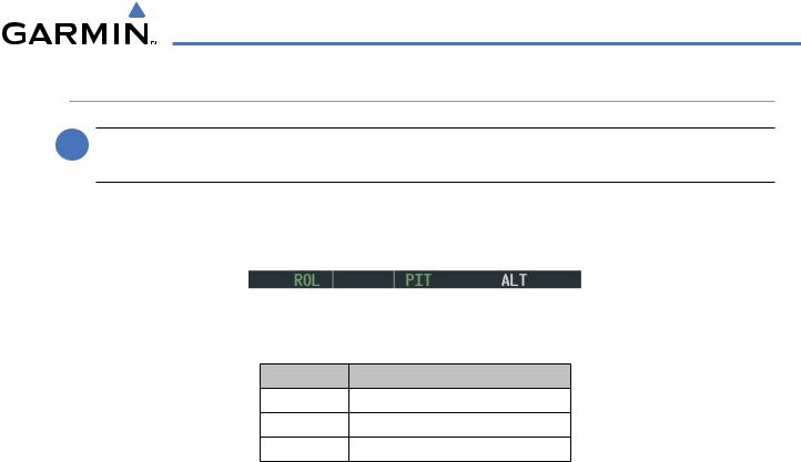
When the flight director is activated, Roll Hold Mode is selected by default. This mode is annunciated as ‘ROL’ in the AFCS Status Box. The current aircraft bank angle is held, subject to the bank angle conditions listed in Table 7-4.
Figure 7-20 Roll Hold Mode Annunciation
Bank Angle |
Flight Director Response |
< 6° Rolls wings level
6° to 22° Maintains current aircraft roll attitude
> 22° Limits bank to 22°
Table 7-4 Roll Hold Mode Responses
CHANGING THE ROLL REFERENCE
The roll reference can be changed by pressing the CWS Button, establishing the desired bank angle, then releasing the CWS Button.
190-00498-03 Rev.A |
Garmin G1000 Pilot’s Guide for Cessna Nav III |
7-23 |
AUTOMATIC FLIGHT CONTROL SYSTEM
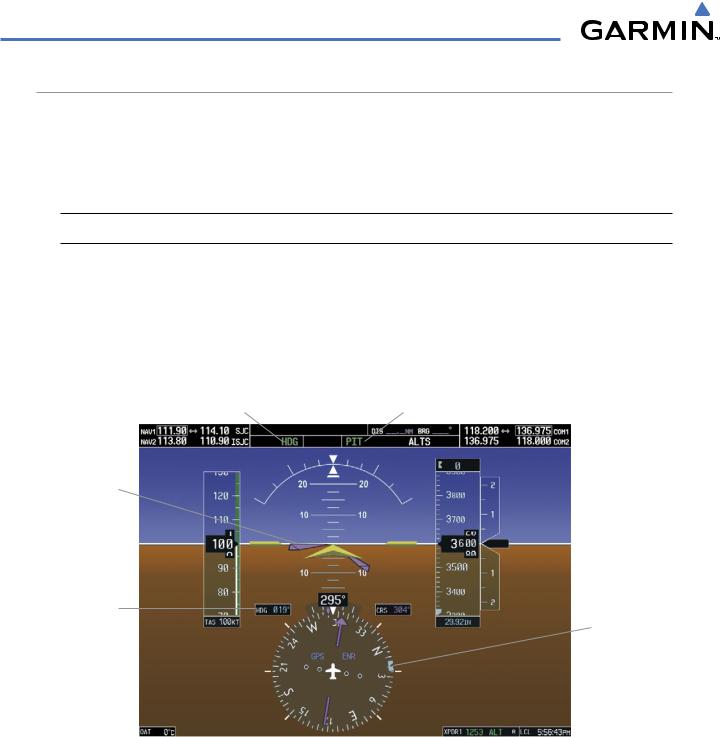
HEADING SELECT MODE (HDG)
Heading Select Mode is activated by pressing the HDG Key. Heading Select Mode acquires and maintains the Selected Heading. The Selected Heading is shown by a light blue bug on the HSI and in the box to the upper left of the HSI.
CHANGING THE SELECTED HEADING
 NOTE: Pressing the HDG Knob synchronize the Selected Heading to the current heading.
The Selected Heading is adjusted using the HDG Knob. Pressing the CWS Button and hand-flying the aircraft does not change the Selected Heading. The autopilot guides the aircraft back to the Selected Heading upon release of the CWS Button.
Turns are commanded in the same direction as Selected Heading Bug movement, even if the Bug is turned more than 180° from the present heading (e.g., a 270° turn to the right). However, Selected Heading changes of more than 340° at a time result in turn reversals.
Heading Select |
Pitch Mode |
Mode Active |
Active |
Command
Bars Track
Selected
Heading
Selected
Heading Selected
Heading
Bug
Figure 7-21 Heading Select Mode
7-24 |
Garmin G1000 Pilot’s Guide for Cessna Nav III |
190-00498-03 Rev.A |
AUTOMATIC FLIGHT CONTROL SYSTEM
NAVIGATION MODE (GPS, VOR, LOC)
 NOTE: The selected navigation receiver must have a valid VOR or LOC signal or active GPS course for the flight director to enter Navigation Mode.
 NOTE: When intercepting a flight plan leg, the flight director gives commands to capture the active leg at approximately a 45° angle to the track between the waypoints defining the active leg. The flight director does not give commands to fly to the starting waypoint of the active leg.
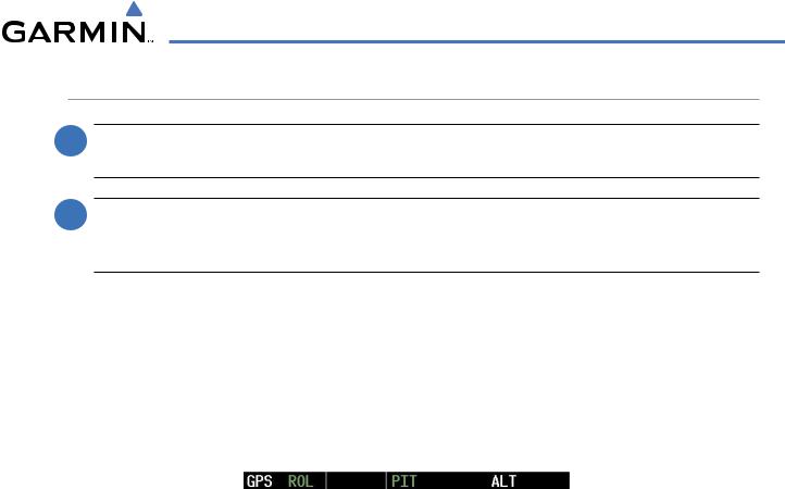
Pressing the NAV Key selects Navigation Mode. Navigation Mode acquires and tracks the selected navigation source (GPS, VOR, LOC). The flight director follows GPS roll steering commands when GPS is the selected navigationsource. WhenthenavigationsourceisVORorLOC,theflightdirectorcreatesrollsteeringcommands from the Selected Course and deviation. Navigation Mode can also be used to fly non-precision GPS and LOC approaches where glideslope capture is not required.
If the Course Deviation Indicator (CDI) shows greater than one dot when the NAVKey is pressed, the selected mode is armed. If the CDI is less than one dot, Navigation Mode is automatically captured when the NAV Key is pressed. The armed annunciation appears in white to the left of the active roll mode.
Figure 7-22 GPS Navigation Mode Armed
When the CDI has automatically switched from GPS to LOC during a LOC/ILS approach, GPS Navigation Mode remains active, providing GPS steering guidance until the localizer signal is captured. LOC Navigation Mode is armed automatically when the navigation source switch takes place if the APR Key is not pressed prior to the automatic source switch.
If Navigation Mode is active and either of the following occur, the flight director reverts to Roll Hold Mode (wings rolled level):
•Different VOR tuned while in VOR Navigation Mode (VOR Navigation Mode reverts to armed)
•Navigation source manually switched (with the CDI Softkey)
•During a LOC/ILS approach the FAF is crossed while in GPS Navigation Mode after the automatic navigation source switch from GPS to LOC
190-00498-03 Rev.A |
Garmin G1000 Pilot’s Guide for Cessna Nav III |
7-25 |
AUTOMATIC FLIGHT CONTROL SYSTEM
CHANGING THE SELECTED COURSE
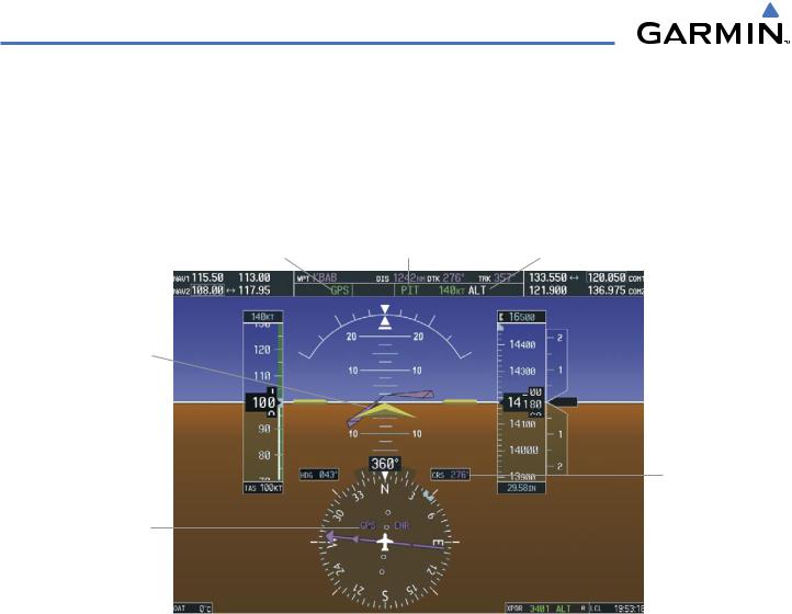
The Selected Course is controlled using the CRS Knob (while in VOR, LOC, or OBS Mode). Pressing the CWS Button and hand-flying the aircraft does not change the Selected Course while in Navigation Mode. The autopilot guides the aircraft back to the Selected Course (or GPS flight plan) when the CWS Button is released.
|
|
Selected Altitude |
GPS Navigation |
Pitch Mode |
Capture Mode |
Mode Active |
Active |
Armed |
Command Bars
Indicate Left
Turn to Track
GPS Course and
Climb to Intercept
Selected Altitude
Selected
Course
GPS is Active Navigation Receiver on HSI
Figure 7-23 Navigation Mode
7-26 |
Garmin G1000 Pilot’s Guide for Cessna Nav III |
190-00498-03 Rev.A |