

ENGINE INDICATION SYSTEM
SECTION 3 ENGINE INDICATION SYSTEM (EIS)
 NOTE: Refer to the Pilot’s Operating Handbook (POH) for limitations.
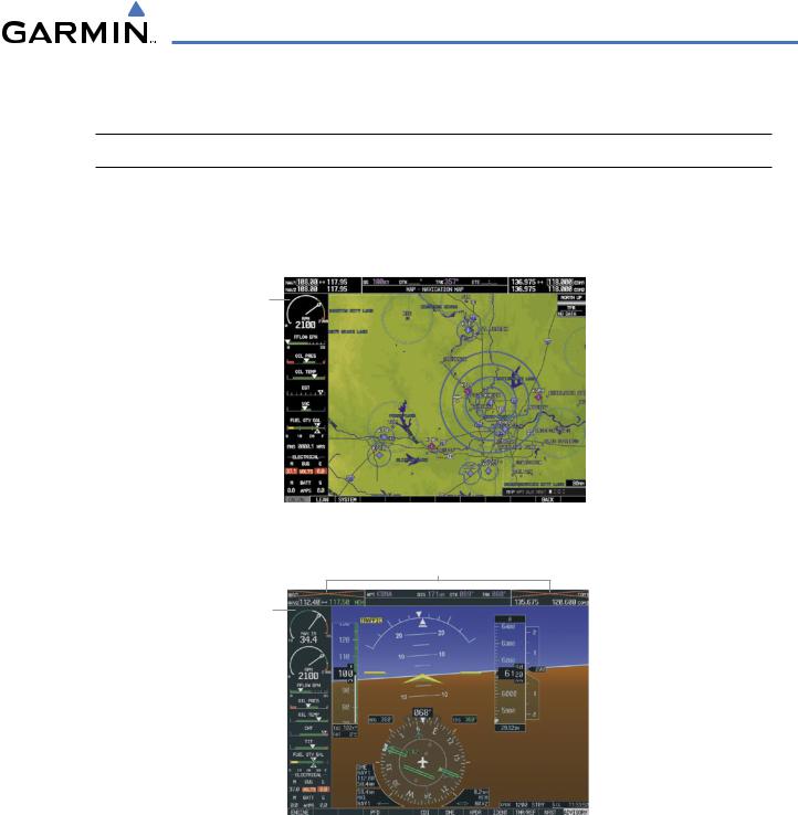
The G1000 Engine Indication System (EIS) displays critical engine, electrical, fuel, and other system parameters on the left side of the Multi Function Display (MFD) during normal operations (Figure 3-1). In reversionary mode (Figure 3-2), the displays are re-configured to present Primary Flight Display (PFD) symbology together with the EIS (refer to the System Overview for information about Reversionary Mode).
EIS
Display
Figure 3-1 Multi Function Display (Normal Operations)
Failed NAV/COM
EIS
Display
Figure 3-2 Primary Flight Display (Reversionary Mode)
Green bands on the instruments indicate normal ranges of operation; yellow and red bands indicate caution and warning, respectively. White or uncolored bands indicate areas outside of normal operation not yet in the caution or warning ranges. When unsafe operating conditions occur, readouts, pointers and labels change color corresponding to the level of the condition; warnings also flash. If sensory data to an instrument becomes invalid or unavailable, a red “X” is shown across the instrument.
190-00498-03 Rev.A |
Garmin G1000 Pilot’s Guide for Cessna Nav III |
3-1 |
ENGINE INDICATION SYSTEM
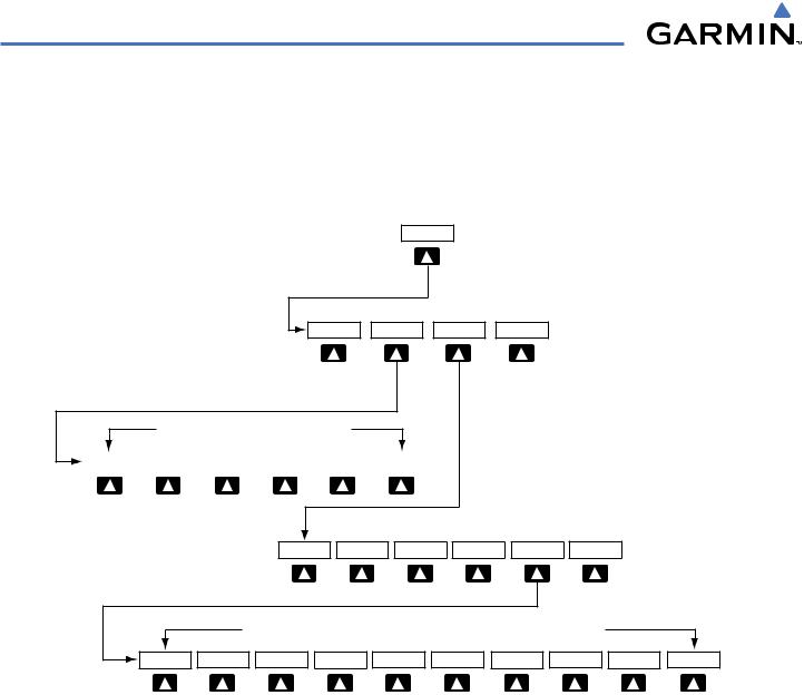
EIS information is presented in three displays, accessed using the ENGINE Softkey on the MFD:
•Engine Display – Default display, shows all critical engine, fuel, and electrical indicators
•Lean Display – Provides engine leaning information
•System Display – Shows numeric readouts of critical engine, fuel, and electrical indicators
|
|
ENGINE |
|
ENGINE |
LEAN |
SYSTEM |
BACK |
Press the ENGINE or BACK Softkey to return to the default Engine Page level.
|
|
|
|
SYSTEM |
|
CYL SLCT |
|
|
|
BACK |
ENGINE |
LEAN |
|
|
|
ASSIST |
|
ENGINE |
LEAN |
SYSTEM |
RST FUEL |
GAL REM |
BACK |
Press the ENGINE Softkey to return to the default Engine Page level.
Press the BACK Softkey to return to the previous softkey level.
ENGINE |
LEAN |
SYSTEM |
-10 GAL |
-1 GAL |
+1 GAL |
+10 GAL |
XX GAL |
XX GAL |
BACK |
X = airframe specific values
Figure 3-3 Engine Softkey Flowchart
3-2 |
Garmin G1000 Pilot’s Guide for Cessna Nav III |
190-00498-03 Rev.A |

ENGINE INDICATION SYSTEM
3.1 ENGINE DISPLAY
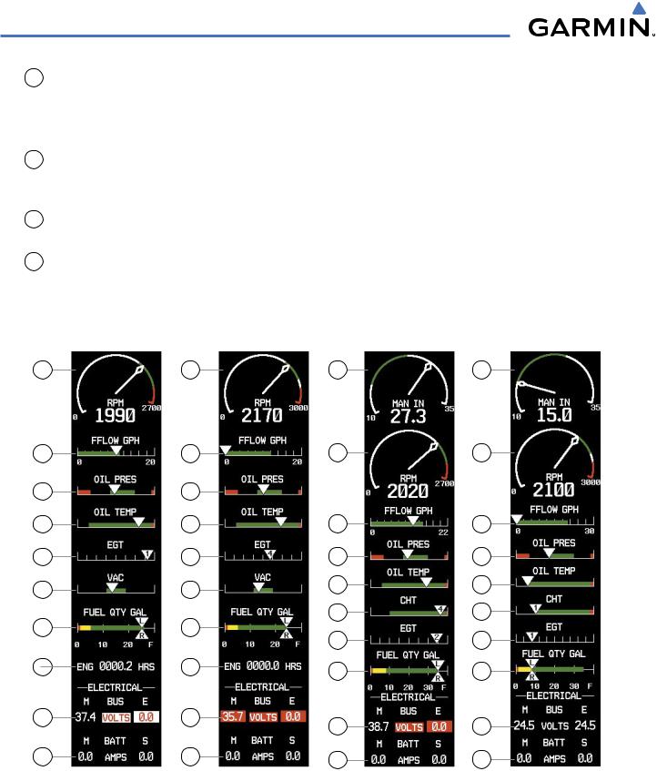
The Engine Display is the default EIS display and can be displayed after viewing other EIS displays by pressing the ENGINE softkey. This display shows the dial gauge(s), horizontal bar indicators, and readouts for critical engine and electrical parameters.
The EIS automatically defaults back to the Engine Display from the Lean or System Display when certain parameters are exceeded. Fluctuations in engine speed and fuel quantity above certain levels, depending on the airframe, also cause reversion back to the Engine Display.
1 Engine Manifold Pressure
Gauge (MAN IN)
Models 182T, T182T, 206H,
T206H
2 Tachometer
(RPM)
3 Fuel Flow Indicator
(FFLOW GPH)
4 Oil Pressure Indicator
(OIL PRES)
5 Oil Temperature Indicator
(OIL TEMP)
Displays engine power in inches of mercury (in Hg)
Turbocharged aircraft – Red range indicates maximum manifold pressure Model T182T – A white tick mark indicates the cruise manifold pressure
Displays propeller speeds in revolutions per minute (rpm) Red range indicates propeller overspeed warning
Models 172S, 206H, and T206H – White high-rpm range indicates above normal operating speeds
Displays the current fuel flow in gallons per hour (gph)
Turbocharged aircraft – A green tick mark indicates maximum takeoff fuel flow
Model T182T – A white tick mark indicates the maximum cruise fuel flow
Displays pressure of the oil supplied to the engine in pounds per square inch (psi)
Displays the engine oil temperature in degrees Fahrenheit (°F)
6 |
Cylinder Head Temperature Displays the head temperature of the hottest cylinder (number shown in |
|
|
Indicator (CHT) |
triangular pointer) in °F |
|
Models 182T, T182T, 206H, |
|
|
T206H |
|
7 |
Exhaust Gas Temperature |
Displays the exhaust gas temperature of the hottest cylinder (number shown |
|
Indicator (EGT) |
in triangular pointer) in °F |
|
Normally-aspirated Aircraft |
|
8 |
Turbine Inlet Temperature |
Displays the temperature at the turbine inlet in °F |
|
Indicator (TIT) |
|
|
Turbocharged Aircraft |
|
9 |
Vacuum Pressure Indicator |
Displays standby vacuum pump pressure |
|
(VAC) |
|
|
Models 172R and 172S |
|
190-00498-03 Rev.A |
Garmin G1000 Pilot’s Guide for Cessna Nav III |
3-3 |
ENGINE INDICATION SYSTEM
10Fuel Quantity Indicator (FUEL QTY GAL)
11Engine Hours (Tach) (ENG HRS)
Models 172R and 172S
12Voltmeter
(M, E BUS VOLTS)
13 Ammeter
(M, S BATT AMPS)
2 |
2 |
3 |
3 |
4 |
4 |
5 |
5 |
7 |
7 |
9 |
9 |
10 |
10 |
11 |
11 |
12 |
12 |
13 |
13 |
Model 172R
Displays the quantity of fuel in gallons (gal) in each tank (left–Landright–R) from zero to full (F)
When full, the indicator displays to 35 gal per side (26 gal for Models 172R and 172S).
Displays a numeric readout for the time in hours (hrs) the engine has been in service
Displays the main and essential bus voltages
Displays the main and standby battery load in amperes
1 |
1 |
2 |
2 |
3 |
|
3 |
4 |
|
4 |
5 |
|
5 |
6 |
|
6 |
7 |
|
7 |
10 |
|
10 |
12 |
|
12 |
13 |
|
13 |
Model 172S |
Model 182T |
Model 206H |
Figure 3-4 Engine Display (Normally-aspirated Aircraft)
3-4 |
Garmin G1000 Pilot’s Guide for Cessna Nav III |
190-00498-03 Rev.A |
ENGINE INDICATION SYSTEM
1
2
3
4
5
6
8
10
12
13
Cruise |
|
Manifold |
1 |
Pressure |
|
|
2 |
Cruise |
3 |
Fuel |
|
Flow |
4 |
|
|
|
5 |
|
6 |
|
8 |
|
10 |
|
12 |
|
13 |
Model T182T |
Model T206H |
Figure 3-5 Engine Display (Turbocharged Aircraft)
Maximum
Takeoff
Fuel Flow
190-00498-03 Rev.A |
Garmin G1000 Pilot’s Guide for Cessna Nav III |
3-5 |