

- •Section 1 System Overview
- •1.1 System Description
- •1.2 Line Replaceable Units (LRU)
- •1.3 G1000 Controls
- •PFD/MFD Controls
- •Audio Panel Controls
- •1.4 Secure Digital (SD) Cards
- •1.5 System Power-up
- •1.6 System Operation
- •Normal Display Operation
- •Reversionary Display Operation
- •AHRS Operation
- •G1000 System Annunciations
- •Softkey Function
- •GPS Receiver Operation
- •1.7 Accessing G1000 Functionality
- •Menus
- •MFD Page Groups
- •MFD System Pages
- •1.8 Display Backlighting
- •Automatic Adjustment
- •Manual Adjustment
- •Section 2 Flight Instruments
- •2.1 Flight Instruments
- •Airspeed Indicator
- •Attitude Indicator
- •Altimeter
- •Vertical Speed Indicator (VSI)
- •Vertical Deviation
- •Horizontal Situation Indicator (HSI)
- •Course Deviation Indicator (CDI)
- •2.2 Supplemental Flight Data
- •Outside Air Temperature
- •Wind Data
- •Vertical Navigation (VNV) Indications
- •2.3 PFD Annunciations and Alerting Functions
- •G1000 System Alerting
- •Marker Beacon Annunciations
- •Traffic Annunciation
- •TAWS Annunciations
- •Altitude Alerting
- •Low Altitude Annunciation
- •Minimum Descent Altitude/Decision Height Alerting
- •2.4 Abnormal Operations
- •Abnormal GPS Conditions
- •Unusual Attitudes
- •Section 3 Engine Indication System (EIS)
- •3.1 Engine Display
- •3.2 Lean Display
- •Normally-aspirated Aircraft
- •Turbocharged Aircraft
- •3.3 System Display
- •Section 4 audio panel and CNS
- •4.1 Overview
- •MFD/PFD Controls and Frequency Display
- •Audio Panel Controls
- •4.2 COM Operation
- •COM Transceiver Selection and Activation
- •COM Transceiver Manual Tuning
- •Quick-Tuning and Activating 121.500 MHz
- •Auto-tuning the COM Frequency
- •Frequency Spacing
- •Automatic Squelch
- •Volume
- •4.3 NAV Operation
- •NAV Radio Selection and Activation
- •NAV Receiver Manual Tuning
- •Auto-tuning a NAV Frequency from the MFD
- •Marker Beacon Receiver
- •DME Tuning (Optional)
- •4.4 GTX 33 Mode S Transponder
- •Transponder Controls
- •Transponder Mode Selection
- •Entering a Transponder Code
- •IDENT Function
- •Flight ID Reporting
- •4.5 Additional Audio Panel Functions
- •Power-Up
- •Mono/Stereo Headsets
- •Speaker
- •Intercom
- •Passenger Address (PA) System
- •Clearance Recorder and Player
- •Entertainment Inputs
- •4.6 Audio Panel Preflight Procedure
- •4.7 Abnormal Operation
- •Stuck Microphone
- •COM Tuning Failure
- •Audio Panel Fail-Safe Operation
- •Reversionary Mode
- •Section 5 Flight Management
- •5.1 Introduction
- •Navigation Status Box
- •5.2 Using Map Displays
- •Map Orientation
- •Map Range
- •Map Panning
- •Measuring Bearing and Distance
- •Topography
- •Map Symbols
- •Airways
- •Track Vector
- •Wind Vector
- •Nav Range Ring
- •Fuel Range Ring
- •5.3 Waypoints
- •Airports
- •Intersections
- •NDBs
- •VORs
- •User Waypoints
- •5.4 Airspaces
- •5.5 Direct-to-Navigation
- •5.6 Flight Planning
- •Flight Plan Creation
- •Adding Waypoints To An Existing Flight Plan
- •Adding Airways to a Flight Plan
- •Adding Procedures To A Stored Flight Plan
- •Flight Plan Storage
- •Flight Plan Editing
- •Along Track Offsets
- •Parallel Track
- •Activating a Flight Plan Leg
- •Inverting a Flight Plan
- •Flight Plan Views
- •Closest Point of FPL
- •5.7 Vertical Navigation
- •Altitude Constraints
- •5.8 Procedures
- •Departures
- •Arrivals
- •Approaches
- •5.9 Trip Planning
- •Trip Planning
- •5.10 RAIM Prediction
- •5.11 Navigating a Flight Plan
- •5.12 Abnormal Operation
- •Section 6 Hazard Avoidance
- •6.1 XM Satellite Weather
- •Activating Services
- •Using XM Satellite Weather Products
- •6.2 WX-500 Stormscope (Optional)
- •Setting Up Stormscope on the Navigation Map
- •Selecting the Stormscope Page
- •6.3 Terrain Proximity
- •Displaying Terrain Proximity Data
- •Terrain Proximity Page
- •6.4 TAWs (Optional)
- •Displaying TAWS Data
- •TAWS Page
- •TAWS Alerts
- •System Status
- •6.5 Traffic Information Service (TIS)
- •Displaying TRAFFIC Data
- •Traffic Map Page
- •TIS Alerts
- •System Status
- •6.6 Traffic Advisory System (TAS) (Optional)
- •TAS Symbology
- •Operation
- •Altitude Display
- •Traffic Map Page Display Range
- •TAS Alerts
- •System Status
- •6.7 ADS-B Traffic (Optional)
- •Section 7 Automatic Flight Control System
- •7.2 Flight Director Operation
- •Activating the Flight Director
- •AFCS Status Box
- •Command Bars
- •Flight Director Modes
- •7.3 Vertical Modes
- •Pitch Hold Mode (PIT)
- •Selected Altitude capture Mode (ALTs)
- •Altitude hold mode (alt)
- •Vertical Speed Mode (VS)
- •Flight Level Change Mode (FLC)
- •Vertical Navigation Modes (VPTH, ALTV)
- •Glidepath Mode (GP) (waas only)
- •Glideslope Mode (GS)
- •Go Around (GA) Mode
- •7.4 Lateral Modes
- •Roll Hold Mode (ROL)
- •Heading Select Mode (HDG)
- •Navigation mode (GPS, VOR, LOC)
- •Approach mode (GPS, VAPP, LOC)
- •Backcourse Mode (BC)
- •7.5 Autopilot Operation
- •Engaging the Autopilot
- •Control Wheel Steering
- •Disengaging the Autopilot
- •7.6 Example Procedures
- •Departure
- •Intercepting a VOR Radial
- •Flying a Flight Plan/GPS Course
- •Descent
- •Approach
- •Go Around/Missed Approach
- •7.7 AFCS Annunciations and Alerts
- •AFCS Status Alerts
- •Overspeed Protection
- •Section 8 Additional Features
- •8.1 SafeTaxi
- •SafeTaxi Cycle Number and Revision
- •8.2 ChartView
- •ChartView Softkeys
- •Terminal Procedures Charts
- •Chart Options
- •Day/Night View
- •ChartView Cycle Number and Expiration Date
- •8.3 FliteCharts
- •FliteCharts Softkeys
- •Terminal Procedures Charts
- •Chart Options
- •Day/Night View
- •FliteCharts Cycle Number and Expiration Date
- •8.4 XM Radio Entertainment (Optional)
- •Activating XM Satellite Radio Services
- •Using XM Radio
- •Automatic Audio Muting
- •8.5 Scheduler
- •8.5 Abnormal Operation
- •Annunciations and Alerts
- •Alert Level Definitions
- •Nav III Aircraft Alerts
- •CO Guardian Messages
- •G1000 System Annunciations
- •Other G1000 Aural Alerts
- •G1000 System Message Advisories
- •AFCS Alerts
- •TAWS ALERTS
- •TAWS System Status Annunciations
- •SD Card Use
- •Jeppesen Databases
- •Garmin Databases
- •Glossary
- •Frequently Asked Questions
- •General TIS Information
- •Introduction
- •TIS vs. TAS/TCAS
- •TIS Limitations
- •Map Symbols
- •Index
HAZARD AVOIDANCE
6.6 TRAFFIC ADVISORY SYSTEM (TAS) (OPTIONAL)
 NOTE: TIS is disabled when Traffic Advisory System (TAS) is installed.
Refer to the Honeywell KTA 870 Series Pilot’s Guide for a detailed discussion of the KTA 870 TAS. The type of traffic system installed is determined by the Traffic Page softkeys.
Figure 6-71 TAS Traffic Softkeys
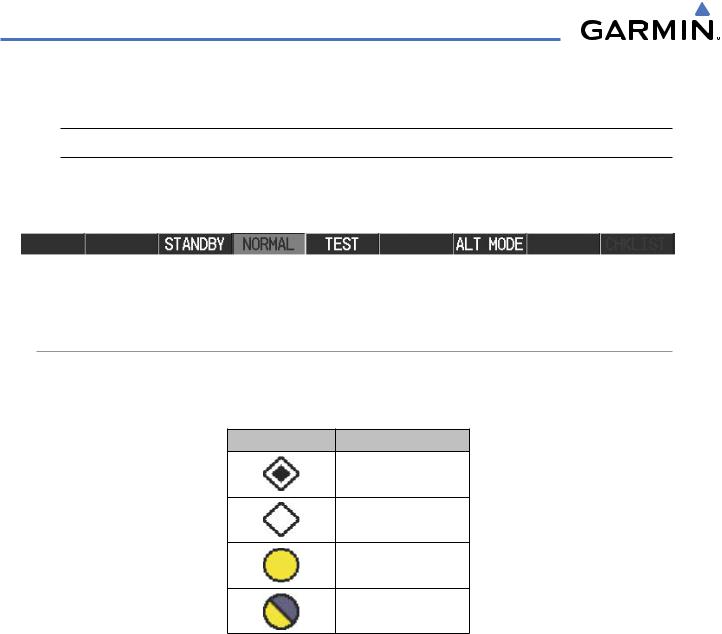
TAS SYMBOLOGY
Traffic Advisory System (TAS) is designed to help in detection and avoidance of other aircraft. TAS uses an onboard interrogator-processor and the Mode S transponder for the air-to-air traffic data link. Traffic is displayed according to TCAS symbology using four different symbols.
TAS Symbol |
Description |
Non-Threat Traffic
Proximity Advisory (PA)
Traffic Advisory (TA)
Traffic Advisory Off Scale
Table 6-14 TAS Symbol Description
A Non-threat Advisory, shown as an open white diamond, indicates that an intruding aircraft is at greater than ±1200 feet relative altitude or the distance is beyond 5 nm.
A Proximity Advisory indicates that the intruding aircraft is within ±1200 feet and is within 5 nm range, but is still not considered a threat.
A Traffic Advisory (TA) alerts the crew to a potentially hazardous intruding aircraft. Closing rate, distance, and vertical separation meet TA criteria. A Traffic Advisory that is beyond the selected display range is indicated by a half TA symbol at the edge of the screen at the relative bearing of the intruder.
6-56 |
Garmin G1000 Pilot’s Guide for Cessna Nav III |
190-00498-03 Rev.A |

HAZARD AVOIDANCE
OPERATION
The unit must be in operating mode for traffic to be displayed. The ability to switch from standby to operating mode on the ground is especially useful for scanning the airspace around the airport before takeoff.
Switching from standby mode to operating mode:
1)On the Traffic Page, press the NORMAL Softkey or press the MENU Key and turn the small FMS knob to select Normal Mode.
2)If using the FMS menu, press the ENT Key to place the KTA 870 in the operating mode.
3)To switch to Standby Mode from the Traffic Page, press the STANDBY Softkey.
The STANDBY Softkey forces the unit into Standby Mode. The NORMAL softkey allows the KTA 870 to switch from Operating Mode to Standby Mode as necessary.
System Self Test
1)Set the range to 2/6 nm.
2)Press the TEST Softkey.
3)Self test takes approximately eight seconds to complete. When completed successfully, traffic symbols is displayed and a voice alert“TAS SystemTest Passed”is heard. If the self test fails,the system reverts to Standby Mode and a voice alert “TAS System Test Failed” is heard.
Displaying traffic on the Traffic Map Page:
1)Use the large FMS Knob to select the Map Page Group.
2)Use the small FMS Knob to select the Traffic Map Page.
3)Press the NORMAL Softkey to begin displaying traffic. OPERATING is displayed in the Traffic mode field.
4)Press the ALT MODE Softkey to change the altitude volume.
5)Press the STANDBY Softkey to place the system in the Standby mode. STANDBY is displayed in theTraffic mode field.
6)Turn the RANGE Knob clockwise to display a larger area or counter-clockwise to display a smaller area.
190-00498-03 Rev.A |
Garmin G1000 Pilot’s Guide for Cessna Nav III |
6-57 |

HAZARD AVOIDANCE
Operating
Mode
Altitude |
Traffic Display |
|
Range |
||
Mode |
||
|
Traffic Advisory, Aircraft is 400’ Below, Climbing
“Non-Bearing” Traffic (Bearing Undetermined),
Distance 8.0 nm, 1100’ Above,
Descending Proximity
Traffic, 1000’
Above,
Descending
Off Scale
Traffic
Figure 6-72 Traffic Map Page
The Traffic Map Page shows surrounding TAS traffic data in relation to the aircraft’s current position and altitude, without basemap clutter. Aircraft orientation is always heading up unless there is no valid heading. Map range is adjustable with the RANGE Knob from 2 to 40 nm, as indicated by the map range rings.
The traffic mode and altitude display mode are annunciated in the upper left corner.
6-58 |
Garmin G1000 Pilot’s Guide for Cessna Nav III |
190-00498-03 Rev.A |
HAZARD AVOIDANCE
DISPLAYING TRAFFIC DATA
Traffic information can be displayed on the following maps when the KTA 870 unit is operating:
• PFD Inset Map |
• Trip Planning Page |
• Navigation Map Page |
• Nearest Pages |
• Traffic Map Page |
• Active Flight Plan Page |
Displaying traffic information (maps other than the Traffic Map Page):
1)Press the MAP Softkey (for the PFD Inset Map, press the INSET Softkey).
2)Press the TRAFFIC Softkey. Traffic is now displayed on the map.
When traffic is selected on maps other than the Traffic Map Page, a traffic icon is shown to indicate TAS is enabled for display.
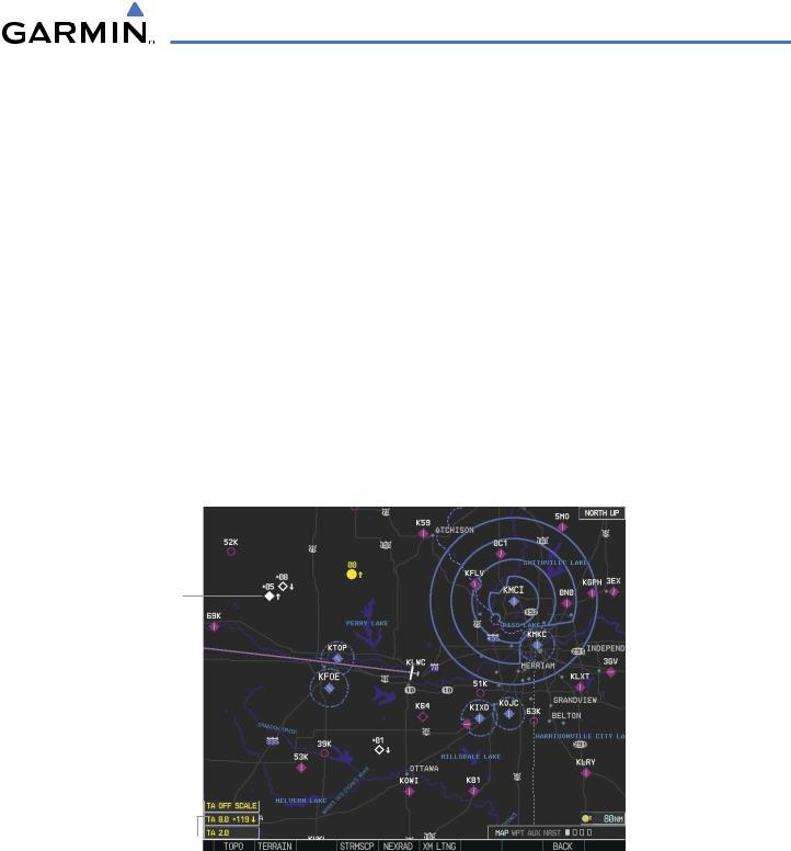
Displaying traffic on the Navigation Map
1)Ensure that the TAS system is operating. With the Navigation Map displayed, press the MAP Softkey.
2)Press the TRAFFIC Softkey. Traffic is now displayed on the map as shown in the figure.
Traffic
Advisory
Proximity
Traffic
Non-Threat
Traffic
TA Off Scale
Banner
Non-Bearing
Traffic Advisories
Figure 6-73 TAS Traffic on Navigation Map
The Navigation Map Page Setup Menu also controls the display of traffic. The setup menu controls the map range settings. Traffic data symbols and labels can be decluttered from the display. If a map range larger than the map range setting is selected, the data is removed from the map. Maps besides the Traffic Map Page use settings based on those selected for the Navigation Map Page.
190-00498-03 Rev.A |
Garmin G1000 Pilot’s Guide for Cessna Nav III |
6-59 |