

AUDIO PANEL AND CNS
4.2 COM OPERATION
COM TRANSCEIVER SELECTION AND ACTIVATION
 NOTE: During PA Mode, the COM MIC Annunciator is extinguished and the COM active frequency color changes to white, indicating that neither COM transmitter is active.
 NOTE: When turning on the G1000 for use, the system remembers the last frequencies used and the active COM transceiver state prior to shutdown.
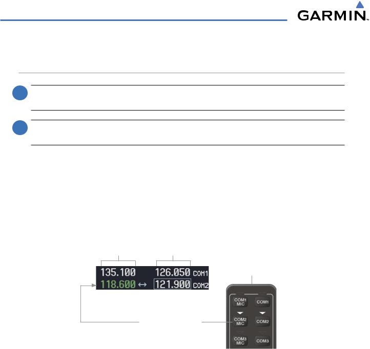
The COM Frequency Box is composed of four fields; the two active frequencies are on the left side and the two standby frequencies are on the right. The COM transceiver is selected for transmitting by pressing the COM MIC Keys on the Audio Panel. During reception of audio from the COM radio selected for transmission, audio from the other COM radio is muted.
An active COM frequency displayed in green indicates that the COM transceiver is selected on the Audio Panel (COM1 MIC or COM2 MIC Key). Both active COM frequencies appearing in white indicate that no COM radio is selected for transmitting [PA Key is selected on the Audio Panel, (T)182T and (T)206H only].
Frequencies in the standby fields are displayed in white.
Active |
Standby |
Fields |
Fields |
Top Section of
the Audio Panel
Tuning Box
COM2 Radio is Selected on the Audio Panel
Figure 4-3 Selecting a COM Radio for Transmit
4-6 |
Garmin G1000 Pilot’s Guide for Cessna Nav III |
190-00498-03 Rev A |
AUDIO PANEL AND CNS
TRANSMIT/RECEIVE INDICATIONS
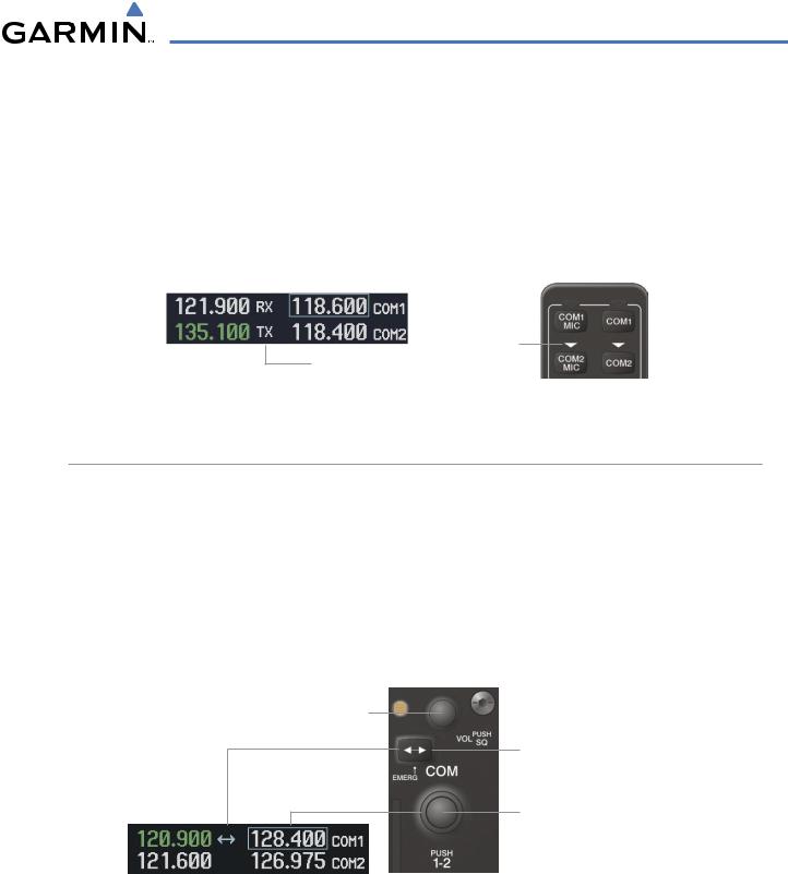
During COM transmission, a white TX appears by the active COM frequency replacing the Frequency Transfer Arrow. On the Audio Panel, when the active COM is transmitting, the active transceiver COM MIC Key Annunciator flashes approximately once per second.
During COM signal reception, a white RX appears by the active COM frequency replacing the Frequency Transfer Arrow. Entertainment audio, if selected, is muted during active COM radio reception. Refer to Additional Audio Panel Functions later in this section, and details on the Data Link Receiver in the Additional Features Section.
Annunciator
Flashes During
Transmit and Transmission
Receive Indicators
Figure 4-4 COM Radio Transmit and Receive Indications
COM TRANSCEIVER MANUAL TUNING
The COM frequency controls and frequency boxes are on the right side of the MFD and PFD.
Manually tuning a COM frequency:
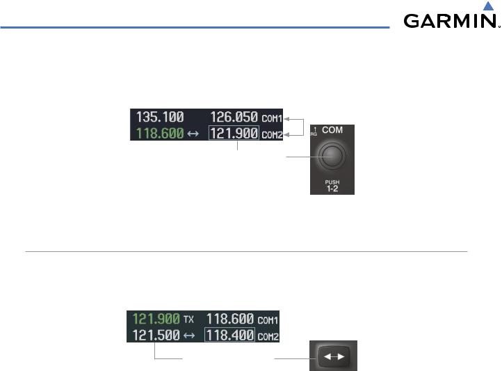
1)Turn the COM Knob to tune the desired frequency in the COM Tuning Box (large knob for MHz; small knob for kHz).
2)Press the Frequency Transfer Key to transfer the frequency to the active field.
3)Adjust the volume level with the COM VOL/SQ Knob.
4)Press the COM VOL/SQ Knob to turn automatic squelch on and off.
Turn the VOL/SQ Knob to adjust volume. Press the Knob to Turn Automatic Squelch On or Off
Press the Frequency Transfer
Key to Transfer COM Frequencies Between Active and Standby Frequency Boxes
Turn the COM Knob to Tune the Frequency in the Tuning Box
Figure 4-5 COM Frequency Tuning
190-00498-03 Rev A |
Garmin G1000 Pilot’s Guide for Cessna Nav III |
4-7 |
AUDIO PANEL AND CNS
SELECTING THE RADIO TO BE TUNED
Press the small COM Knob to transfer the frequency tuning box and Frequency Transfer Arrow between the upper and lower radio frequency fields.
Press the COM Knob to
Switch the Tuning Box From
One COM Radio to the Other
Figure 4-6 Switching COM Tuning Boxes
QUICK-TUNING AND ACTIVATING 121.500 MHZ
Pressing and holding the COM Frequency Transfer Key for two seconds automatically loads the emergency COM frequency (121.500 MHz) in the active field of the COM radio selected for tuning (the one with the transfer arrow). In the example shown, pressing the Audio Panel COM2 MIC Key activates the transceiver.
Press for Two Seconds to
Load 121.500 MHz
Figure 4-7 Quickly Tuning 121.500 MHz
4-8 |
Garmin G1000 Pilot’s Guide for Cessna Nav III |
190-00498-03 Rev A |

AUDIO PANEL AND CNS
AUTO-TUNING THE COM FREQUENCY
COM frequencies can be automatically tuned from the following:
• Nearest Airports Window (PFD) |
• NRST – Nearest Frequencies Page (ARTCC, FSS, WX) |
• WPT – Airport Information Page |
• NRST – Nearest Airspaces Page |
• NRST – Nearest Airports Page |
|
AUTO-TUNING FROM THE PFD
COM frequencies for the nearest airports can be automatically tuned from the Nearest Airports Window on the PFD. When the desired frequency is entered, it becomes a standby frequency. Pressing the Frequency Transfer Key places this frequency into the COM Active Frequency Field.
Auto-tuning a COM frequency for a nearby airport from the PFD:
1)Press the NRST Softkey on the PFD to open the NearestAirportsWindow. A list of 25 nearest airport identifiers and COM frequencies is displayed.
2)Turn the FMS Knob to scroll through the list and highlight the desired COM frequency.
3)Press the ENT Key to load the COM frequency into the COM Standby Tuning Box.
4)Press the Frequency Transfer Key to transfer the frequency to the COM Active Frequency Field.
|
|
Press the NRST |
|
|
Softkey to Open |
|
||
|
|
the Nearest |
|
|
|
Figure 4-8 Nearest Airports Window (PFD) |
|
Airports Window |
|
|
190-00498-03 Rev A |
Garmin G1000 Pilot’s Guide for Cessna Nav III |
4-9 |

AUDIO PANEL AND CNS
AUTO-TUNING FROM THE MFD
Frequencies can be automatically loaded into the COM Frequency Box from pages in the NRST or WPT page group by highlighting the frequency and pressing the ENT Key (Figures 4-9, 4-10, and 4-11).
Auto-tuning a COM frequency from the WPT and NRST Pages:
1)From any page that the COM frequency can be auto-tuned,activate the cursor by pressing the FMS Knob or the appropriate softkey.
2)Turn the FMS Knob to place the cursor on the desired COM frequency (Figure 4-11).
3)Press the ENT Key to load the COM frequency into the standby field of the selected COM radio.
4)Press the Frequency Transfer Key to transfer the frequency to the COM Active Frequency Field.
Press the ENT Key to Load a Highlighted Frequency into the COM Standby
Turn the FMS Frequency Box Knob to Scroll
Through a List
of Frequencies
Figure 4-9 Frequency Auto-Tuning from the MFD
Or:
1)Press the MENU Key to display the page menu.
2)Turn the large FMS Knob to scroll through the menu options.
3)Press the ENT Key to place the cursor on the desired selection.
4)Scroll through the frequency selections with the FMS Knob or the ENT Key.
5)Press the ENT Key to load the COM frequency into the standby field of the selected COM radio.
6)Press the Frequency Transfer Key to transfer the frequency to the COM Active Frequency Field.
Nearest Airports Menu |
Nearest Frequencies Menu |
Nearest Airspaces Menu |
Figure 4-10 Nearest Pages Menus
4-10 |
Garmin G1000 Pilot’s Guide for Cessna Nav III |
190-00498-03 Rev A |
AUDIO PANEL AND CNS
On the WPT - Airport Information Page, the cursor can be placed on the frequency field by pressing the FMS Knob and scrolling through the list. The frequency is transferred to the COM Standby Field with the ENT Key.
Press Frequency
Transfer Key to Load
Frequency into COM
Active Frequency Field
Selected Airport
Identifier and
Information
Runway
Information
Press ENT Key to Load Frequency into COM Standby Field. Cursor then advances to next frequency.
Press INFO Softkey for AIRPORT, RUNWAYS, and FREQUENCIES Windows
Figure 4-11 WPT – Airport Information Page
190-00498-03 Rev A |
Garmin G1000 Pilot’s Guide for Cessna Nav III |
4-11 |
AUDIO PANEL AND CNS
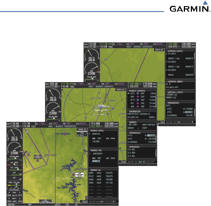
COM frequencies can also be auto-tuned from the NRST – Nearest Airspaces, NRST – Nearest Frequencies, and NRST – Nearest Airports Pages on the MFD in a similar manner using the appropriate softkeys or MENU Key, the FMS Knob, and the ENT Key.
Figure 4-12 NRST – Nearest Frequencies, NRST – Nearest Airports, and NRST – Nearest Airspaces Pages
4-12 |
Garmin G1000 Pilot’s Guide for Cessna Nav III |
190-00498-03 Rev A |