

- •Section 1 System Overview
- •1.1 System Description
- •1.2 Line Replaceable Units (LRU)
- •1.3 G1000 Controls
- •PFD/MFD Controls
- •Audio Panel Controls
- •1.4 Secure Digital (SD) Cards
- •1.5 System Power-up
- •1.6 System Operation
- •Normal Display Operation
- •Reversionary Display Operation
- •AHRS Operation
- •G1000 System Annunciations
- •Softkey Function
- •GPS Receiver Operation
- •1.7 Accessing G1000 Functionality
- •Menus
- •MFD Page Groups
- •MFD System Pages
- •1.8 Display Backlighting
- •Automatic Adjustment
- •Manual Adjustment
- •Section 2 Flight Instruments
- •2.1 Flight Instruments
- •Airspeed Indicator
- •Attitude Indicator
- •Altimeter
- •Vertical Speed Indicator (VSI)
- •Vertical Deviation
- •Horizontal Situation Indicator (HSI)
- •Course Deviation Indicator (CDI)
- •2.2 Supplemental Flight Data
- •Outside Air Temperature
- •Wind Data
- •Vertical Navigation (VNV) Indications
- •2.3 PFD Annunciations and Alerting Functions
- •G1000 System Alerting
- •Marker Beacon Annunciations
- •Traffic Annunciation
- •TAWS Annunciations
- •Altitude Alerting
- •Low Altitude Annunciation
- •Minimum Descent Altitude/Decision Height Alerting
- •2.4 Abnormal Operations
- •Abnormal GPS Conditions
- •Unusual Attitudes
- •Section 3 Engine Indication System (EIS)
- •3.1 Engine Display
- •3.2 Lean Display
- •Normally-aspirated Aircraft
- •Turbocharged Aircraft
- •3.3 System Display
- •Section 4 audio panel and CNS
- •4.1 Overview
- •MFD/PFD Controls and Frequency Display
- •Audio Panel Controls
- •4.2 COM Operation
- •COM Transceiver Selection and Activation
- •COM Transceiver Manual Tuning
- •Quick-Tuning and Activating 121.500 MHz
- •Auto-tuning the COM Frequency
- •Frequency Spacing
- •Automatic Squelch
- •Volume
- •4.3 NAV Operation
- •NAV Radio Selection and Activation
- •NAV Receiver Manual Tuning
- •Auto-tuning a NAV Frequency from the MFD
- •Marker Beacon Receiver
- •DME Tuning (Optional)
- •4.4 GTX 33 Mode S Transponder
- •Transponder Controls
- •Transponder Mode Selection
- •Entering a Transponder Code
- •IDENT Function
- •Flight ID Reporting
- •4.5 Additional Audio Panel Functions
- •Power-Up
- •Mono/Stereo Headsets
- •Speaker
- •Intercom
- •Passenger Address (PA) System
- •Clearance Recorder and Player
- •Entertainment Inputs
- •4.6 Audio Panel Preflight Procedure
- •4.7 Abnormal Operation
- •Stuck Microphone
- •COM Tuning Failure
- •Audio Panel Fail-Safe Operation
- •Reversionary Mode
- •Section 5 Flight Management
- •5.1 Introduction
- •Navigation Status Box
- •5.2 Using Map Displays
- •Map Orientation
- •Map Range
- •Map Panning
- •Measuring Bearing and Distance
- •Topography
- •Map Symbols
- •Airways
- •Track Vector
- •Wind Vector
- •Nav Range Ring
- •Fuel Range Ring
- •5.3 Waypoints
- •Airports
- •Intersections
- •NDBs
- •VORs
- •User Waypoints
- •5.4 Airspaces
- •5.5 Direct-to-Navigation
- •5.6 Flight Planning
- •Flight Plan Creation
- •Adding Waypoints To An Existing Flight Plan
- •Adding Airways to a Flight Plan
- •Adding Procedures To A Stored Flight Plan
- •Flight Plan Storage
- •Flight Plan Editing
- •Along Track Offsets
- •Parallel Track
- •Activating a Flight Plan Leg
- •Inverting a Flight Plan
- •Flight Plan Views
- •Closest Point of FPL
- •5.7 Vertical Navigation
- •Altitude Constraints
- •5.8 Procedures
- •Departures
- •Arrivals
- •Approaches
- •5.9 Trip Planning
- •Trip Planning
- •5.10 RAIM Prediction
- •5.11 Navigating a Flight Plan
- •5.12 Abnormal Operation
- •Section 6 Hazard Avoidance
- •6.1 XM Satellite Weather
- •Activating Services
- •Using XM Satellite Weather Products
- •6.2 WX-500 Stormscope (Optional)
- •Setting Up Stormscope on the Navigation Map
- •Selecting the Stormscope Page
- •6.3 Terrain Proximity
- •Displaying Terrain Proximity Data
- •Terrain Proximity Page
- •6.4 TAWs (Optional)
- •Displaying TAWS Data
- •TAWS Page
- •TAWS Alerts
- •System Status
- •6.5 Traffic Information Service (TIS)
- •Displaying TRAFFIC Data
- •Traffic Map Page
- •TIS Alerts
- •System Status
- •6.6 Traffic Advisory System (TAS) (Optional)
- •TAS Symbology
- •Operation
- •Altitude Display
- •Traffic Map Page Display Range
- •TAS Alerts
- •System Status
- •6.7 ADS-B Traffic (Optional)
- •Section 7 Automatic Flight Control System
- •7.2 Flight Director Operation
- •Activating the Flight Director
- •AFCS Status Box
- •Command Bars
- •Flight Director Modes
- •7.3 Vertical Modes
- •Pitch Hold Mode (PIT)
- •Selected Altitude capture Mode (ALTs)
- •Altitude hold mode (alt)
- •Vertical Speed Mode (VS)
- •Flight Level Change Mode (FLC)
- •Vertical Navigation Modes (VPTH, ALTV)
- •Glidepath Mode (GP) (waas only)
- •Glideslope Mode (GS)
- •Go Around (GA) Mode
- •7.4 Lateral Modes
- •Roll Hold Mode (ROL)
- •Heading Select Mode (HDG)
- •Navigation mode (GPS, VOR, LOC)
- •Approach mode (GPS, VAPP, LOC)
- •Backcourse Mode (BC)
- •7.5 Autopilot Operation
- •Engaging the Autopilot
- •Control Wheel Steering
- •Disengaging the Autopilot
- •7.6 Example Procedures
- •Departure
- •Intercepting a VOR Radial
- •Flying a Flight Plan/GPS Course
- •Descent
- •Approach
- •Go Around/Missed Approach
- •7.7 AFCS Annunciations and Alerts
- •AFCS Status Alerts
- •Overspeed Protection
- •Section 8 Additional Features
- •8.1 SafeTaxi
- •SafeTaxi Cycle Number and Revision
- •8.2 ChartView
- •ChartView Softkeys
- •Terminal Procedures Charts
- •Chart Options
- •Day/Night View
- •ChartView Cycle Number and Expiration Date
- •8.3 FliteCharts
- •FliteCharts Softkeys
- •Terminal Procedures Charts
- •Chart Options
- •Day/Night View
- •FliteCharts Cycle Number and Expiration Date
- •8.4 XM Radio Entertainment (Optional)
- •Activating XM Satellite Radio Services
- •Using XM Radio
- •Automatic Audio Muting
- •8.5 Scheduler
- •8.5 Abnormal Operation
- •Annunciations and Alerts
- •Alert Level Definitions
- •Nav III Aircraft Alerts
- •CO Guardian Messages
- •G1000 System Annunciations
- •Other G1000 Aural Alerts
- •G1000 System Message Advisories
- •AFCS Alerts
- •TAWS ALERTS
- •TAWS System Status Annunciations
- •SD Card Use
- •Jeppesen Databases
- •Garmin Databases
- •Glossary
- •Frequently Asked Questions
- •General TIS Information
- •Introduction
- •TIS vs. TAS/TCAS
- •TIS Limitations
- •Map Symbols
- •Index

FLIGHT MANAGEMENT
3)Press the ENT Key. A confirmation window is displayed listing the arrival procedure.
4)With‘OK’ highlighted,press the ENT Key. To cancel the removal request,highlight‘CANCEL’ and press the ENT Key.
Or:
1)Press the FPL Key to display the Active Flight Plan Page (MFD) or the Active Flight Plan Window (PFD)
2)Press the FMS Knob, and turn to highlight the arrival header in the active flight plan.
3)Press the CLR Key. A confirmation window is displayed listing the arrival procedure.
4)With‘OK’ highlighted,press the ENT Key. To cancel the removal request,highlight‘CANCEL’ and press the ENT Key.
APPROACHES
 NOTE: If certain GPS parameters (WAAS,RAIM,etc.) are not available,some published approach procedures for the desired airport may not be displayed in the list of available approaches.
An Approach Procedure (APPR) can be loaded at any airport that has one available, and provides guidance for non-precision and precision approaches to airports with published instrument approach procedures. Only one approach can be loaded at a time in a flight plan. If an approach is loaded when another approach is already in the active flight plan, the new approach replaces the previous approach. The route is defined by selection of an approach and the transition waypoints.
Whenever an approach is selected, the choice to either “load” or “activate” is given. “Loading” adds the approach to the end of the flight plan without immediately using it for navigation guidance. This allows continued navigation via the intermediate waypoints in the original flight plan, but keeps the procedure available on the Active Flight Plan Page for quick activation when needed. “Activating” also adds the procedure to the end of the flight plan but immediately begins to provide guidance to the first waypoint in the approach.
Whenselectinganapproach,a“GPS”designationtotherightoftheprocedurenameindicatestheprocedure can be flown using the GPS receiver. Some procedures do not have this designation, meaning the GPS receiver can be used for supplemental navigation guidance only. If the GPS receiver cannot be used for primary guidance, the appropriate navigation receiver must be used for the selected approach (e.g., VOR or ILS). The final course segment of ILS approaches, for example, must be flown by tuning the NAV receiver to the proper frequency and selecting that NAV receiver on the CDI.
5-96 |
Garmin G1000 Pilot’s Guide for Cessna Nav III |
190-00498-03 Rev.A |
FLIGHT MANAGEMENT
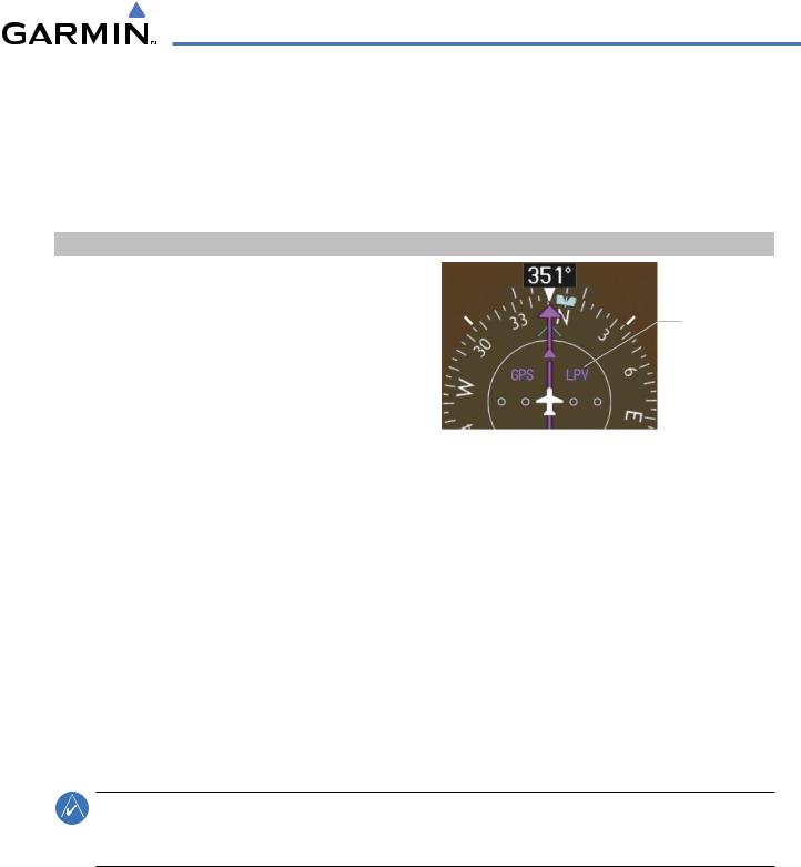
TheG1000WAASGPSallowsforflyingLNAV,LNAV/VNAV,andLPVapproachesaccordingtothepublished chart. LNAV+V is a standard LNAV approach with advisory vertical guidance provided for assistance in maintaining a constant vertical glidepath similar to an ILS glideslope on approach. This guidance is displayed on the G1000 PFD in the same location as the ILS glideslope using a magenta diamond. In all cases where LNAV+V is indicated by the system during an approach, LNAV minima are used. The active approach type is annunciated on the HSI as shown in the following table:
HSI Annunciation |
Description |
Example on HSI |
|
LNAV |
GPS approach using published LNAV |
|
|
|
minima |
|
|
LNAV+V |
GPS approach using published LNAV |
Approach Type |
|
|
minima. Advisory vertical guidance is |
||
|
- LNAV |
||
|
provided |
- LNAV+V |
|
|
|
- L/VNAV |
|
L/VNAV |
GPS approach using published LNAV/ |
||
- LPV |
|||
(available only if |
VNAV minima |
|
|
WAAS equipped) |
|
|
|
LPV |
GPS approach using published LPV |
|
|
(available only if |
minima |
|
|
WAAS equipped |
|
|
Table 5-9 Approach Types
LOADING AN APPROACH INTO THE ACTIVE FLIGHT PLAN
Loading an approach into the active flight plan using the PROC Key:
1)Press the PROC Key. The Procedures Window is displayed.
2)Highlight ‘SELECT APPROACH, and press the ENT Key. The Approach Loading Page is displayed.
3)Select an approach from the list and press the ENT Key.
4)Select a transition (if required) and press the ENT Key.
5)Press the ENT Key with ‘LOAD?’ highlighted to load the arrival procedure; or turn the large FMS Knob to highlight ‘ACTIVATE’ and press the ENT Key to load and activate the approach procedure.
NOTE: When GPS is not approved for the selected final approach course, the message ‘NOT APPROVED FOR GPS’ is displayed. GPS provides guidance to the approach, but the HSI must to be switched to a NAV receiver to fly the final course of the approach.
190-00498-03 Rev.A |
Garmin G1000 Pilot’s Guide for Cessna Nav III |
5-97 |
FLIGHT MANAGEMENT
Available Procedure Actions |
Destination Airport |
||||
|
|
|
|
|
|
|
|
|
|
|
|
|
|
|
|
|
|
|
|
|
|
|
|
|
|
|
|
|
|
|
|
|
|
|
|
|
|
|
|
|
|
|
|
|
|
|
|
|
|
Loaded |
|
Procedures |
|
Approach |
|
Preview |
Approach |
|
Choices |
||||||
|
|
|
|
||||||||||||
|
|
|
|||||||||||||
|
|
|
|
|
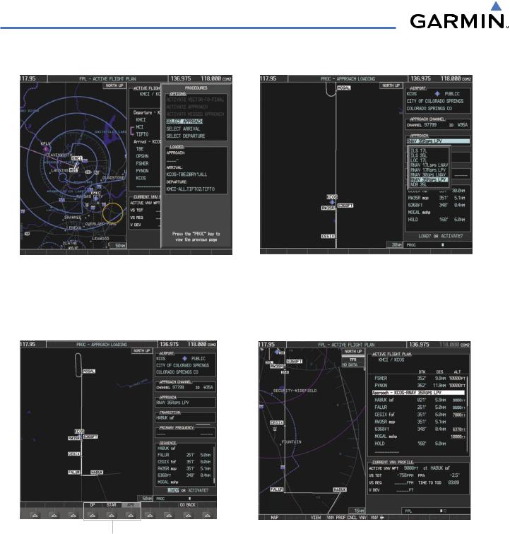
Figure 5-91 Approach Selection |
|
|
|
|
|
|||||
Selected Approach |
|
|
|
|
|
Loaded Approach |
|||||||||
|
|
|
|
|
|
|
|
|
|
|
|
|
|
|
|
|
|
|
|
|
|
|
|
|
|
|
|
|
|
|
|
|
|
|
|
|
|
|
|
|
|
|
|
|
|
|
|
|
|
|
|
|
|
|
|
|
|
|
|
|
|
|
|
Procedure Loading Page Selection Softkeys
Figure 5-92 Approach Loading
Viewing available approaches at an airport:
1)From the Airport Information Page (first page in the WPT group), press the APR Softkey. The Departure Information Page is displayed, defaulting to the airport displayed on the Airport information Page.
2)To select another airport, press the FMS Knob to activate the cursor, enter an identifier/facility name/city, and press the ENT Key.
5-98 |
Garmin G1000 Pilot’s Guide for Cessna Nav III |
190-00498-03 Rev.A |

FLIGHT MANAGEMENT
3)Press the FMS Knob, then turn the large FMS Knob to highlight the Approach. The approach is previewed on the map.
4)Turn the small FMS Knob to view the available approaches. Press the ENT Key to select the approach. The cursor moves to the Runway box. The approach is previewed on the map.
5)Turn the small FMS Knob to view the available runways. Press the ENT Key to select the runway. The cursor moves to the Transition box. The approach is previewed on the map.
6)Turn the small FMS Knob to view the available transitions.Press the ENT Key to select the transition. The cursor moves to the Sequence box. The approach is previewed on the map.
7)Press the INFO Softkey to return to the Airport Information Page.
Loading an approach into the active flight plan from the Nearest Airport Page:
1)Select the Nearest Airports Page.
2)Press the FMS Knob, then turn the large FMS Knob to highlight the desired nearest airport. The airport is previewed on the map.
3)Press the APR Softkey; or press the MENU Key, highlight ‘Select Approach Window’, and press the ENT Key.
4)Turn the FMS Knob to highlight the desired approach.
5)Press the LD APR Softkey; or press the MENU Key, highlight ‘Load Approach’, and press the ENT Key. The Approach Loading Page is displayed with the transitions field highlighted.
6)Turn the FMS Knob to highlight the desired transition.
7)Press the ENT Key. The ‘LOAD?’ field is highlighted.
8)Press the ENT Key with ‘LOAD?’ highlighted to load the arrival procedure; or turn the large FMS Knob to highlight ‘ACTIVATE’ and press the ENT Key to load and activate the approach procedure.The G1000 continues navigating the current flight plan until the approach is activated. When GPS is not approved for the selected final approach course, the message ‘NOT APPROVED FOR GPS’ is displayed. GPS provides guidance to the approach, but the HSI must to be switched to a NAV receiver to fly the final course of the approach.
ACTIVATING AN APPROACH
A previously loaded approach can be activated from the Procedures Window.
Activating a previously loaded approach:
1)Press the PROC Key. The Procedures Window is displayed with ‘Activate Approach’ highlighted.
2)Press the ENT Key to activate the approach.
In many cases, it may be easiest to “load” the full approach while still some distance away, enroute to the destination airport. Later, if vectored to final, use the steps above to select ‘Activate Vector-To-Final’ — which makes the inbound course to the FAF waypoint active.
Activating a previously loaded approach with vectors to final:
1)Press the PROC Key to display the Procedures Window.
2)Highlight ‘ACTIVATE VECTOR-TO-FINAL’ and press the ENT Key.
190-00498-03 Rev.A |
Garmin G1000 Pilot’s Guide for Cessna Nav III |
5-99 |

FLIGHT MANAGEMENT
Loading and activating an approach using the MENU Key:
1)From the Approach Loading Page, press the MENU Key. The page menu is displayed with ‘Load & Activate Approach’ highlighted.
2)Press the ENT Key. When GPS is not approved for the selected final approach course, the message ‘NOT APPROVED FOR GPS’ is displayed. GPS provides guidance to the approach, but the HSI must to be switched to a NAV receiver to fly the final course of the approach.
REMOVING AN APPROACH FROM THE ACTIVE FLIGHT PLAN
When plans change while flying IFR, approaches can be easily removed from the Active Flight Plan..
Removing an approach from the active flight plan:
1)Press the FPL Key to display the Active Flight Plan Page (MFD) or the Active Flight Plan Window (PFD)
2)Press the MENU Key, and highlight ‘Remove Approach’.
3)Press the ENT Key. A confirmation window is displayed listing the approach procedure.
4)With ‘OK’ highlighted, press the ENT Key. To cancel the removal, highlight ‘CANCEL’ and press the ENT Key.
Or:
1)Press the FPL Key to display the Active Flight Plan Page (MFD) or the Active Flight Plan Window (PFD)
2)Press the FMS Knob, and turn to highlight the approach header in the active flight plan.
3)Press the CLR Key. A confirmation window is displayed listing the approach procedure.
4)With ‘OK’ highlighted, press the ENT Key. To cancel the removal, highlight ‘CANCEL’ and press the ENT Key.
MISSED APPROACH
Activating a missed approach in the active flight plan:
1)Press the PROC Key.
2)Turn the FMS Knob to highlight ‘ACTIVATE MISSED APPROACH’.
3)Press the ENT Key. The aircraft automatically sequences to the MAHP.
5-100 |
Garmin G1000 Pilot’s Guide for Cessna Nav III |
190-00498-03 Rev.A |
FLIGHT MANAGEMENT
COURSE TO FIX
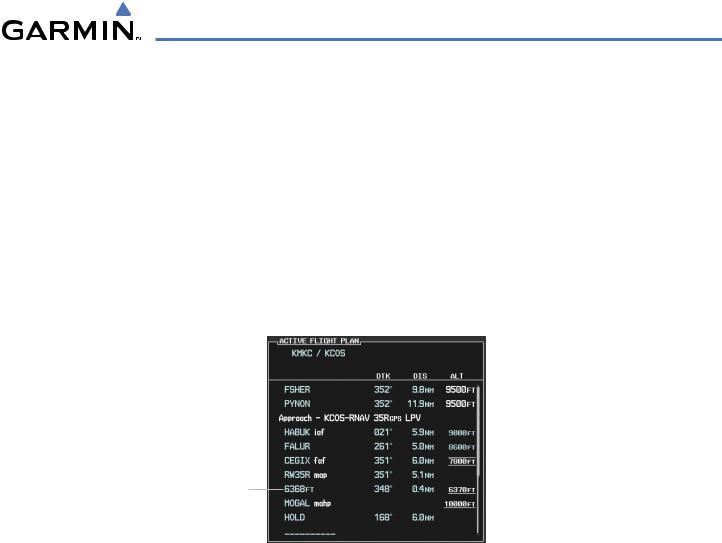
In a missed approach procedure, the fix immediately following the MAP (in this case ‘6368FT’) is not part of the published procedure. It is simply a fix that defines a leg which guides the aircraft along the runway centerline until the required altitude to make the first turn on the missed approach is exceeded. In this case, if the aircraft altitude is below the specified altitude (6,368 feet) after crossing the MAP, a direct-to is established to this fix until an altitude of 6,368 feet reached. After reaching 6,368 feet, a direct-to is established to the published fix (in this case MOGAL). If the aircraft altitude is above the specified altitude after crossing the MAP, a direct-to is established to the published fix (MOGAL) to begin the missed approach procedure. The altitude constraint value defaults to 400 feet AGL when the fix is not part of the published procedure.
In some missed approach procedures this altitude fix may be part of the published procedure. If the aircraft altitude is lower than this prescribed altitude, a direct-to is established to this fix when the missed approach procedure is activated.
Course to Fix Waypoint
Figure 5-93 Course to Fix
190-00498-03 Rev.A |
Garmin G1000 Pilot’s Guide for Cessna Nav III |
5-101 |