

- •Section 1 System Overview
- •1.1 System Description
- •1.2 Line Replaceable Units (LRU)
- •1.3 G1000 Controls
- •PFD/MFD Controls
- •Audio Panel Controls
- •1.4 Secure Digital (SD) Cards
- •1.5 System Power-up
- •1.6 System Operation
- •Normal Display Operation
- •Reversionary Display Operation
- •AHRS Operation
- •G1000 System Annunciations
- •Softkey Function
- •GPS Receiver Operation
- •1.7 Accessing G1000 Functionality
- •Menus
- •MFD Page Groups
- •MFD System Pages
- •1.8 Display Backlighting
- •Automatic Adjustment
- •Manual Adjustment
- •Section 2 Flight Instruments
- •2.1 Flight Instruments
- •Airspeed Indicator
- •Attitude Indicator
- •Altimeter
- •Vertical Speed Indicator (VSI)
- •Vertical Deviation
- •Horizontal Situation Indicator (HSI)
- •Course Deviation Indicator (CDI)
- •2.2 Supplemental Flight Data
- •Outside Air Temperature
- •Wind Data
- •Vertical Navigation (VNV) Indications
- •2.3 PFD Annunciations and Alerting Functions
- •G1000 System Alerting
- •Marker Beacon Annunciations
- •Traffic Annunciation
- •TAWS Annunciations
- •Altitude Alerting
- •Low Altitude Annunciation
- •Minimum Descent Altitude/Decision Height Alerting
- •2.4 Abnormal Operations
- •Abnormal GPS Conditions
- •Unusual Attitudes
- •Section 3 Engine Indication System (EIS)
- •3.1 Engine Display
- •3.2 Lean Display
- •Normally-aspirated Aircraft
- •Turbocharged Aircraft
- •3.3 System Display
- •Section 4 audio panel and CNS
- •4.1 Overview
- •MFD/PFD Controls and Frequency Display
- •Audio Panel Controls
- •4.2 COM Operation
- •COM Transceiver Selection and Activation
- •COM Transceiver Manual Tuning
- •Quick-Tuning and Activating 121.500 MHz
- •Auto-tuning the COM Frequency
- •Frequency Spacing
- •Automatic Squelch
- •Volume
- •4.3 NAV Operation
- •NAV Radio Selection and Activation
- •NAV Receiver Manual Tuning
- •Auto-tuning a NAV Frequency from the MFD
- •Marker Beacon Receiver
- •DME Tuning (Optional)
- •4.4 GTX 33 Mode S Transponder
- •Transponder Controls
- •Transponder Mode Selection
- •Entering a Transponder Code
- •IDENT Function
- •Flight ID Reporting
- •4.5 Additional Audio Panel Functions
- •Power-Up
- •Mono/Stereo Headsets
- •Speaker
- •Intercom
- •Passenger Address (PA) System
- •Clearance Recorder and Player
- •Entertainment Inputs
- •4.6 Audio Panel Preflight Procedure
- •4.7 Abnormal Operation
- •Stuck Microphone
- •COM Tuning Failure
- •Audio Panel Fail-Safe Operation
- •Reversionary Mode
- •Section 5 Flight Management
- •5.1 Introduction
- •Navigation Status Box
- •5.2 Using Map Displays
- •Map Orientation
- •Map Range
- •Map Panning
- •Measuring Bearing and Distance
- •Topography
- •Map Symbols
- •Airways
- •Track Vector
- •Wind Vector
- •Nav Range Ring
- •Fuel Range Ring
- •5.3 Waypoints
- •Airports
- •Intersections
- •NDBs
- •VORs
- •User Waypoints
- •5.4 Airspaces
- •5.5 Direct-to-Navigation
- •5.6 Flight Planning
- •Flight Plan Creation
- •Adding Waypoints To An Existing Flight Plan
- •Adding Airways to a Flight Plan
- •Adding Procedures To A Stored Flight Plan
- •Flight Plan Storage
- •Flight Plan Editing
- •Along Track Offsets
- •Parallel Track
- •Activating a Flight Plan Leg
- •Inverting a Flight Plan
- •Flight Plan Views
- •Closest Point of FPL
- •5.7 Vertical Navigation
- •Altitude Constraints
- •5.8 Procedures
- •Departures
- •Arrivals
- •Approaches
- •5.9 Trip Planning
- •Trip Planning
- •5.10 RAIM Prediction
- •5.11 Navigating a Flight Plan
- •5.12 Abnormal Operation
- •Section 6 Hazard Avoidance
- •6.1 XM Satellite Weather
- •Activating Services
- •Using XM Satellite Weather Products
- •6.2 WX-500 Stormscope (Optional)
- •Setting Up Stormscope on the Navigation Map
- •Selecting the Stormscope Page
- •6.3 Terrain Proximity
- •Displaying Terrain Proximity Data
- •Terrain Proximity Page
- •6.4 TAWs (Optional)
- •Displaying TAWS Data
- •TAWS Page
- •TAWS Alerts
- •System Status
- •6.5 Traffic Information Service (TIS)
- •Displaying TRAFFIC Data
- •Traffic Map Page
- •TIS Alerts
- •System Status
- •6.6 Traffic Advisory System (TAS) (Optional)
- •TAS Symbology
- •Operation
- •Altitude Display
- •Traffic Map Page Display Range
- •TAS Alerts
- •System Status
- •6.7 ADS-B Traffic (Optional)
- •Section 7 Automatic Flight Control System
- •7.2 Flight Director Operation
- •Activating the Flight Director
- •AFCS Status Box
- •Command Bars
- •Flight Director Modes
- •7.3 Vertical Modes
- •Pitch Hold Mode (PIT)
- •Selected Altitude capture Mode (ALTs)
- •Altitude hold mode (alt)
- •Vertical Speed Mode (VS)
- •Flight Level Change Mode (FLC)
- •Vertical Navigation Modes (VPTH, ALTV)
- •Glidepath Mode (GP) (waas only)
- •Glideslope Mode (GS)
- •Go Around (GA) Mode
- •7.4 Lateral Modes
- •Roll Hold Mode (ROL)
- •Heading Select Mode (HDG)
- •Navigation mode (GPS, VOR, LOC)
- •Approach mode (GPS, VAPP, LOC)
- •Backcourse Mode (BC)
- •7.5 Autopilot Operation
- •Engaging the Autopilot
- •Control Wheel Steering
- •Disengaging the Autopilot
- •7.6 Example Procedures
- •Departure
- •Intercepting a VOR Radial
- •Flying a Flight Plan/GPS Course
- •Descent
- •Approach
- •Go Around/Missed Approach
- •7.7 AFCS Annunciations and Alerts
- •AFCS Status Alerts
- •Overspeed Protection
- •Section 8 Additional Features
- •8.1 SafeTaxi
- •SafeTaxi Cycle Number and Revision
- •8.2 ChartView
- •ChartView Softkeys
- •Terminal Procedures Charts
- •Chart Options
- •Day/Night View
- •ChartView Cycle Number and Expiration Date
- •8.3 FliteCharts
- •FliteCharts Softkeys
- •Terminal Procedures Charts
- •Chart Options
- •Day/Night View
- •FliteCharts Cycle Number and Expiration Date
- •8.4 XM Radio Entertainment (Optional)
- •Activating XM Satellite Radio Services
- •Using XM Radio
- •Automatic Audio Muting
- •8.5 Scheduler
- •8.5 Abnormal Operation
- •Annunciations and Alerts
- •Alert Level Definitions
- •Nav III Aircraft Alerts
- •CO Guardian Messages
- •G1000 System Annunciations
- •Other G1000 Aural Alerts
- •G1000 System Message Advisories
- •AFCS Alerts
- •TAWS ALERTS
- •TAWS System Status Annunciations
- •SD Card Use
- •Jeppesen Databases
- •Garmin Databases
- •Glossary
- •Frequently Asked Questions
- •General TIS Information
- •Introduction
- •TIS vs. TAS/TCAS
- •TIS Limitations
- •Map Symbols
- •Index

FLIGHT MANAGEMENT
CHANGING FLIGHT PLAN COMMENTS (NAMES)
The comment field (or name) of each flight plan can be changed to something that is useful for identification and sorting.
Changing the active flight plan comment:
1)Press the FPL Key to display the Active Flight Plan Page.
2)Press the FMS Knob to activate the cursor and turn the large FMS Knob to highlight the comment field.
3)Use the FMS Knobs to edit the comment.
4)Press the ENT Key to accept the changes.
Changing a stored flight plan comment:
1)Press the FPL Key to display the Active Flight Plan Page.
2)Turn the small FMS Knob clockwise one click to display the Flight Plan Catalog Page.
3)Press the FMS Knob to activate the cursor and turn the FMS Knob to highlight the flight plan to be edited.
4)Press the EDIT Softkey; or press the MENU Key, select ‘Edit Flight Plan’ and press the ENT Key. The Stored Flight Plan Page is displayed.
5)Turn the large FMS Knob to highlight the comment field.
6)Use the FMS Knobs to edit the comment.
7)Press the ENT Key to accept the changes.
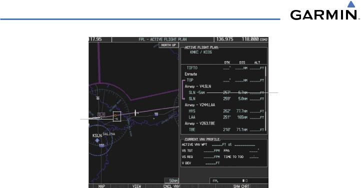
ALONG TRACK OFFSETS
A waypoint having an “along track offset” distance from an existing waypoint can be entered into a flight plan. Along track offset waypoints lie along the path of the existing flight plan, and can be used to make the system reach a specified altitude before or after reaching the specified flight plan waypoint. Offset distances can be entered from 1 to 99 nm in increments of 1 nm. Entering a negative offset distance results in an along track offset waypoint inserted before the selected waypoint, whereas entering a positive offset distance results in an along track offset waypoint inserted after the selected waypoint. Multiple offset waypoints are allowed.
A waypoint must be adjacent to its parent waypoint in the flight plan, so the system limits the along-track distance to less than the length of the leg before or after the selected waypoint. If the selected waypoint is the active waypoint, the distance is limited to less than the distance to go to the active waypoint. Assigning an along track offset to a leg with indeterminate length is not permitted. An along track offset is not allowed at or after the final approach fix of an approach.
An along track offset distance cannot be modified once entered. If the along track offset distance must be changed, the existing along track offset waypoint must be deleted and a new one created with the new offset distance.
190-00498-03 Rev.A |
Garmin G1000 Pilot’s Guide for Cessna Nav III |
5-75 |
FLIGHT MANAGEMENT
Along Track Offset Waypoint and Distance from Flight Plan Waypoint
Along Track Offset Waypoint and Distance
Figure 5-73 Along Track Offset
Entering an along track offset distance:
1)Press the FPL Key to display the Active Flight Plan Page (MFD) or the Active Flight Plan Window (PFD).
2)Press the FMS Knob to activate the cursor (not required on the PFD) and turn the large FMS Knob to highlight the waypoint for the along track offset.
3)Press the ATK OFST Softkey (MFD only); or press the MENU Key, highlight ‘Create ATK Offset Waypoint’, and press the ENT Key.
4)Enter a positive or negative offset distance in the range of +/- 1 to 99 nm.
5)Press the ENT Key to create the offset waypoint.
5-76 |
Garmin G1000 Pilot’s Guide for Cessna Nav III |
190-00498-03 Rev.A |
FLIGHT MANAGEMENT
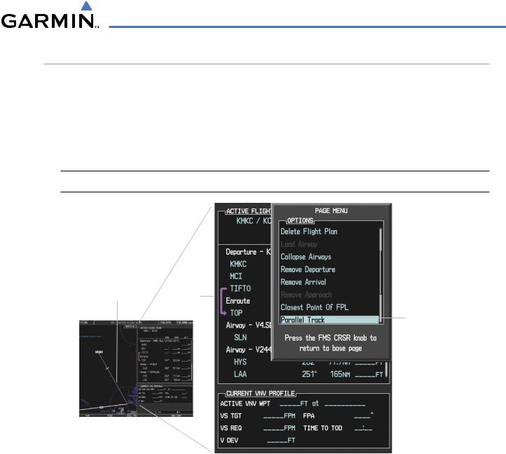
PARALLEL TRACK
The Parallel Track (PTK) feature allows creation of a parallel course offset of 1 to 50 nm left or right of the current flight plan. When Parallel Track is activated, the course line drawn on the map pages shows the parallel course, and waypoint names have a lower case “p” placed after the identifier.
Using direct-to, loading an approach, a holding pattern, or editing and activating the flight plan automatically cancels Parallel Track. Parallel Track is also cancelled if a course change occurs greater than 120° or the parallel tracks overlap as a result of the course change.
 NOTE: Vertical navigation is unavailable while the Parallel Track feature is active.
Active Flight Plan prior to Parallel Track
Selecting Parallel Track
Figure 5-74 Active Flight Plan Window - Selecting Parallel Track
Activating parallel track:
1)Press the FPL Key to display the Active Flight Plan Page (MFD) or the Active Flight Plan Window (PFD)
2)Press the MENU Key, highlight ‘Parallel Track’, and press the ENT Key. The Parallel Track Window is displayed with the direction field highlighted.
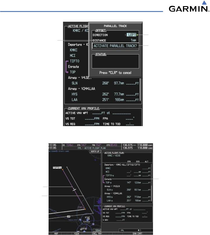
3)Turn the small FMS Knob to select ‘Left’ or ‘Right’ and press the ENT Key. The ‘DISTANCE’ field is highlighted.
4)Turn the small FMS Knob to enter a distance from 1-99 nm and press the ENT Key. ‘ACTIVATE PARALLEL TRACK’ is highlighted.
5)Press the ENT Key to activate parallel track. Press the FMS Knob or the CLR Key to cancel the parallel track activation.
190-00498-03 Rev.A |
Garmin G1000 Pilot’s Guide for Cessna Nav III |
5-77 |
FLIGHT MANAGEMENT
Offset Direction
Offset Distance
Activation Prompt
Figure 5-75 Parallel Track Window
Parallel Track
Original Track
Parallel Track Waypoints
- TIFTO-p - TOP-p - SLN-p - HYS-p - LAA-p
Activating Parallel Track affects the entire active flight segment (e.g., enroute)
Figure 5-76 Parallel Track Active
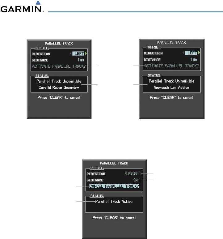
If the parallel track proposed by the offset direction and distance is not allowed by the system, the activation prompt is displayed, but disabled. Parallel Track cannot be activated if a course is set using direct-to or if the active leg is the first leg of the departure procedure. Attempting to activate parallel track with these conditions results in the message ‘Parallel Track Unavailable Invalid Route Geometry’. If an approach leg is active the status indicates that the system is unable to activate the parallel track with the message ‘Parallel Track Unavailable
5-78 |
Garmin G1000 Pilot’s Guide for Cessna Nav III |
190-00498-03 Rev.A |
FLIGHT MANAGEMENT
Approach Leg Active’. If the offset direction and distance results in an unreasonable route geometry the status indicates that the system is unable to activate the parallel track because of invalid geometry.
Subdued Prompt
(Unavailable)
Unavailable Status
Invalid Approach
Geometry Active
Figure 5-77 Parallel Track Unavailable
If the active leg is not a track between two fixes (TF) or a course to a fix (DF) leg, the status indicates that the system is unable to activate the parallel track because parallel track is not available for the active leg type.
Offset Direction &
Distance Subdued
(Unavailable)
Cancel Prompt
Active Status
Figure 5-78 Cancelling Parallel Track
Cancelling parallel track:
1)Press the FPL Key to display the Active Flight Plan Page (MFD) or the Active Flight Plan Window (PFD)
2)Press the MENU Key, highlight ‘Parallel Track’, and press the ENT Key. The Parallel Track Window is displayed with ‘CANCEL PARALLEL TRACK?’ highlighted.
3)Press the ENT Key.
190-00498-03 Rev.A |
Garmin G1000 Pilot’s Guide for Cessna Nav III |
5-79 |