

- •Section 1 System Overview
- •1.1 System Description
- •1.2 Line Replaceable Units (LRU)
- •1.3 G1000 Controls
- •PFD/MFD Controls
- •Audio Panel Controls
- •1.4 Secure Digital (SD) Cards
- •1.5 System Power-up
- •1.6 System Operation
- •Normal Display Operation
- •Reversionary Display Operation
- •AHRS Operation
- •G1000 System Annunciations
- •Softkey Function
- •GPS Receiver Operation
- •1.7 Accessing G1000 Functionality
- •Menus
- •MFD Page Groups
- •MFD System Pages
- •1.8 Display Backlighting
- •Automatic Adjustment
- •Manual Adjustment
- •Section 2 Flight Instruments
- •2.1 Flight Instruments
- •Airspeed Indicator
- •Attitude Indicator
- •Altimeter
- •Vertical Speed Indicator (VSI)
- •Vertical Deviation
- •Horizontal Situation Indicator (HSI)
- •Course Deviation Indicator (CDI)
- •2.2 Supplemental Flight Data
- •Outside Air Temperature
- •Wind Data
- •Vertical Navigation (VNV) Indications
- •2.3 PFD Annunciations and Alerting Functions
- •G1000 System Alerting
- •Marker Beacon Annunciations
- •Traffic Annunciation
- •TAWS Annunciations
- •Altitude Alerting
- •Low Altitude Annunciation
- •Minimum Descent Altitude/Decision Height Alerting
- •2.4 Abnormal Operations
- •Abnormal GPS Conditions
- •Unusual Attitudes
- •Section 3 Engine Indication System (EIS)
- •3.1 Engine Display
- •3.2 Lean Display
- •Normally-aspirated Aircraft
- •Turbocharged Aircraft
- •3.3 System Display
- •Section 4 audio panel and CNS
- •4.1 Overview
- •MFD/PFD Controls and Frequency Display
- •Audio Panel Controls
- •4.2 COM Operation
- •COM Transceiver Selection and Activation
- •COM Transceiver Manual Tuning
- •Quick-Tuning and Activating 121.500 MHz
- •Auto-tuning the COM Frequency
- •Frequency Spacing
- •Automatic Squelch
- •Volume
- •4.3 NAV Operation
- •NAV Radio Selection and Activation
- •NAV Receiver Manual Tuning
- •Auto-tuning a NAV Frequency from the MFD
- •Marker Beacon Receiver
- •DME Tuning (Optional)
- •4.4 GTX 33 Mode S Transponder
- •Transponder Controls
- •Transponder Mode Selection
- •Entering a Transponder Code
- •IDENT Function
- •Flight ID Reporting
- •4.5 Additional Audio Panel Functions
- •Power-Up
- •Mono/Stereo Headsets
- •Speaker
- •Intercom
- •Passenger Address (PA) System
- •Clearance Recorder and Player
- •Entertainment Inputs
- •4.6 Audio Panel Preflight Procedure
- •4.7 Abnormal Operation
- •Stuck Microphone
- •COM Tuning Failure
- •Audio Panel Fail-Safe Operation
- •Reversionary Mode
- •Section 5 Flight Management
- •5.1 Introduction
- •Navigation Status Box
- •5.2 Using Map Displays
- •Map Orientation
- •Map Range
- •Map Panning
- •Measuring Bearing and Distance
- •Topography
- •Map Symbols
- •Airways
- •Track Vector
- •Wind Vector
- •Nav Range Ring
- •Fuel Range Ring
- •5.3 Waypoints
- •Airports
- •Intersections
- •NDBs
- •VORs
- •User Waypoints
- •5.4 Airspaces
- •5.5 Direct-to-Navigation
- •5.6 Flight Planning
- •Flight Plan Creation
- •Adding Waypoints To An Existing Flight Plan
- •Adding Airways to a Flight Plan
- •Adding Procedures To A Stored Flight Plan
- •Flight Plan Storage
- •Flight Plan Editing
- •Along Track Offsets
- •Parallel Track
- •Activating a Flight Plan Leg
- •Inverting a Flight Plan
- •Flight Plan Views
- •Closest Point of FPL
- •5.7 Vertical Navigation
- •Altitude Constraints
- •5.8 Procedures
- •Departures
- •Arrivals
- •Approaches
- •5.9 Trip Planning
- •Trip Planning
- •5.10 RAIM Prediction
- •5.11 Navigating a Flight Plan
- •5.12 Abnormal Operation
- •Section 6 Hazard Avoidance
- •6.1 XM Satellite Weather
- •Activating Services
- •Using XM Satellite Weather Products
- •6.2 WX-500 Stormscope (Optional)
- •Setting Up Stormscope on the Navigation Map
- •Selecting the Stormscope Page
- •6.3 Terrain Proximity
- •Displaying Terrain Proximity Data
- •Terrain Proximity Page
- •6.4 TAWs (Optional)
- •Displaying TAWS Data
- •TAWS Page
- •TAWS Alerts
- •System Status
- •6.5 Traffic Information Service (TIS)
- •Displaying TRAFFIC Data
- •Traffic Map Page
- •TIS Alerts
- •System Status
- •6.6 Traffic Advisory System (TAS) (Optional)
- •TAS Symbology
- •Operation
- •Altitude Display
- •Traffic Map Page Display Range
- •TAS Alerts
- •System Status
- •6.7 ADS-B Traffic (Optional)
- •Section 7 Automatic Flight Control System
- •7.2 Flight Director Operation
- •Activating the Flight Director
- •AFCS Status Box
- •Command Bars
- •Flight Director Modes
- •7.3 Vertical Modes
- •Pitch Hold Mode (PIT)
- •Selected Altitude capture Mode (ALTs)
- •Altitude hold mode (alt)
- •Vertical Speed Mode (VS)
- •Flight Level Change Mode (FLC)
- •Vertical Navigation Modes (VPTH, ALTV)
- •Glidepath Mode (GP) (waas only)
- •Glideslope Mode (GS)
- •Go Around (GA) Mode
- •7.4 Lateral Modes
- •Roll Hold Mode (ROL)
- •Heading Select Mode (HDG)
- •Navigation mode (GPS, VOR, LOC)
- •Approach mode (GPS, VAPP, LOC)
- •Backcourse Mode (BC)
- •7.5 Autopilot Operation
- •Engaging the Autopilot
- •Control Wheel Steering
- •Disengaging the Autopilot
- •7.6 Example Procedures
- •Departure
- •Intercepting a VOR Radial
- •Flying a Flight Plan/GPS Course
- •Descent
- •Approach
- •Go Around/Missed Approach
- •7.7 AFCS Annunciations and Alerts
- •AFCS Status Alerts
- •Overspeed Protection
- •Section 8 Additional Features
- •8.1 SafeTaxi
- •SafeTaxi Cycle Number and Revision
- •8.2 ChartView
- •ChartView Softkeys
- •Terminal Procedures Charts
- •Chart Options
- •Day/Night View
- •ChartView Cycle Number and Expiration Date
- •8.3 FliteCharts
- •FliteCharts Softkeys
- •Terminal Procedures Charts
- •Chart Options
- •Day/Night View
- •FliteCharts Cycle Number and Expiration Date
- •8.4 XM Radio Entertainment (Optional)
- •Activating XM Satellite Radio Services
- •Using XM Radio
- •Automatic Audio Muting
- •8.5 Scheduler
- •8.5 Abnormal Operation
- •Annunciations and Alerts
- •Alert Level Definitions
- •Nav III Aircraft Alerts
- •CO Guardian Messages
- •G1000 System Annunciations
- •Other G1000 Aural Alerts
- •G1000 System Message Advisories
- •AFCS Alerts
- •TAWS ALERTS
- •TAWS System Status Annunciations
- •SD Card Use
- •Jeppesen Databases
- •Garmin Databases
- •Glossary
- •Frequently Asked Questions
- •General TIS Information
- •Introduction
- •TIS vs. TAS/TCAS
- •TIS Limitations
- •Map Symbols
- •Index
HAZARD AVOIDANCE
6.5 TRAFFIC INFORMATION SERVICE (TIS)
WARNING: TheTraffic Information Service (TIS) is intended for advisory use only. TIS is intended to help the pilot locate traffic visually. It is the responsibility of the pilot to see and maneuver to avoid traffic.
NOTE: TIS is available only when the aircraft is within the service volume of a TIS-capable terminal radar site. Aircraft without an operating transponder are invisible to both Traffic Advisory Systems (TAS) and TIS. Aircraft without altitude reporting capability are shown without altitude separation data or climb descent indication.
 NOTE: TIS is disabled if a Traffic Advisory System (TAS) is installed.
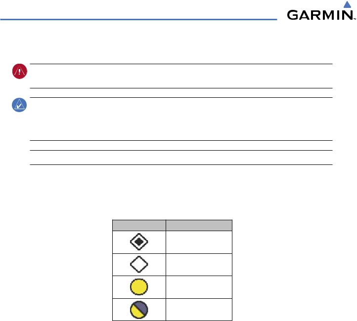
Traffic Information Service (TIS) is designed to help in detection and avoidance of other aircraft. TIS uses the Mode S transponder for the traffic data link. TIS receives traffic information from ground stations, and is updated every 5 seconds. The G1000 displays up to eight traffic targets within a 7.5-nm radius, from 3000 feet below to 3500 feet above the requesting aircraft. Traffic is displayed according to TCAS symbology using four different symbols (Table 6-10).
TIS Symbol |
Description |
Non-Threat Traffic
Proximity Advisory (PA)
Traffic Advisory (TA)
Traffic Advisory Off Scale
Table 6-10 TIS Traffic Symbols
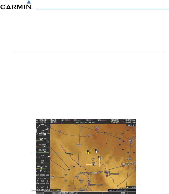
ProximityAdvisories(PAs)aredefinedastrafficwithinthe5.0-nmrange,within±1200feetofaltitudeseparation. They are not Traffic Advisories (TA), which alert the crew to intruding aircraft. When traffic meets the advisory criteria for the TA, a solid yellow circle symbol is generated. A TA which is detected but is outside the range of the map on which traffic is displayed are indicated with a message in the lower left corner of the map.
TIS also provides a vector line showing the direction in which the traffic is moving, to the nearest 45°. Traffic information for which TIS is unable to determine the bearing (non-bearing traffic) is displayed in the center of the Traffic Map Page (Figure 6-68) or in a banner at the lower left corner of maps other than the Traffic Map Page on which traffic can be displayed.
6-48 |
Garmin G1000 Pilot’s Guide for Cessna Nav III |
190-00498-03 Rev.A |
HAZARD AVOIDANCE
The altitude difference between the requesting aircraft and other intruder aircraft is displayed above/below the traffic symbol in hundreds of feet. If the other aircraft is above the requesting aircraft, the altitude separation appears above the traffic symbol; if below, the altitude separation appears below. Altitude trend is displayed as an up/down arrow (for speeds greater than 500 fpm in either direction) to the right of the target symbol. Traffic symbols for aircraft without altitude reporting capability appear without altitude separation or climb/descent information.
DISPLAYING TRAFFIC DATA
Traffic information can be displayed on the following maps (when TIS is operating):
• PFD Inset Map |
• Trip Planning Page |
• Navigation Map Page |
• Nearest Pages |
• Traffic Map Page |
• Active Flight Plan Page |
Displaying traffic information (maps other than the Traffic Map Page):
1)Press the MAP Softkey (for the PFD Inset Map, select the INSET Softkey).
2)Press the TRAFFIC Softkey. Traffic is now displayed on the map.
When traffic is selected on maps other than the Traffic Map Page, an icon is shown to indicate the feature is enabled for display.
Traffic Advisory
Traffic Display Enabled
Traffic Status Banner
Figure 6-64 TIS Traffic on the Navigation Map Page
The Navigation Map Page Setup Menu provides a means in addition to the softkey for enabling/disabling display of traffic. The setup menu also controls the map range settings above which traffic data (symbols and labels) are decluttered from the display. If a map range larger than the map range setting is selected, the data is removed from the map. Maps besides the Traffic Map Page use settings based on those selected for the Navigation Map Page.
190-00498-03 Rev.A |
Garmin G1000 Pilot’s Guide for Cessna Nav III |
6-49 |

HAZARD AVOIDANCE
Customizing traffic display on the Navigation Map Page:
1)Select the Navigation Map Page.
2)Press the MENU Key.
3)With ‘Map Setup’ highlighted, press the ENT Key (Figure 6-65).
4)Turn the small FMS Knob to select the ‘Traffic’ Group and press the ENT Key (Figure 6-66).
5)Turn the large FMS Knob or press the ENT Key to scroll though product selections (Figure 6-67).
•TRAFFIC – Turns the display of traffic data on or off
•TRAFFIC MODE – Selects the traffic mode for display; select from:
-All Traffic - Displays all traffic
-TA/PA - Displays Traffic Alerts and Proximity Advisories
-TA ONLY - Displays Traffic Alerts only
•TRAFFIC SMBL – Selects the maximum range at which traffic symbols are shown
•TRAFFIC LBL – Selects the maximum range at which traffic labels are shown (with the option to turn off)
6)Turn the small FMS Knob to scroll though options for each product (ON/OFF, range settings, etc.).
7)Press the ENT Key to select an option.
8)Press the FMS Knob or CLR Key to return to the Navigation Map Page with the changed settings.
Figure 6-65 Navigation Map Page Menu
Figure 6-66 Navigation Map Page Setup Menu |
Figure 6-67 Navigation Map Page Setup Menu,Traffic Group |
6-50 |
Garmin G1000 Pilot’s Guide for Cessna Nav III |
190-00498-03 Rev.A |
HAZARD AVOIDANCE
TRAFFIC MAP PAGE
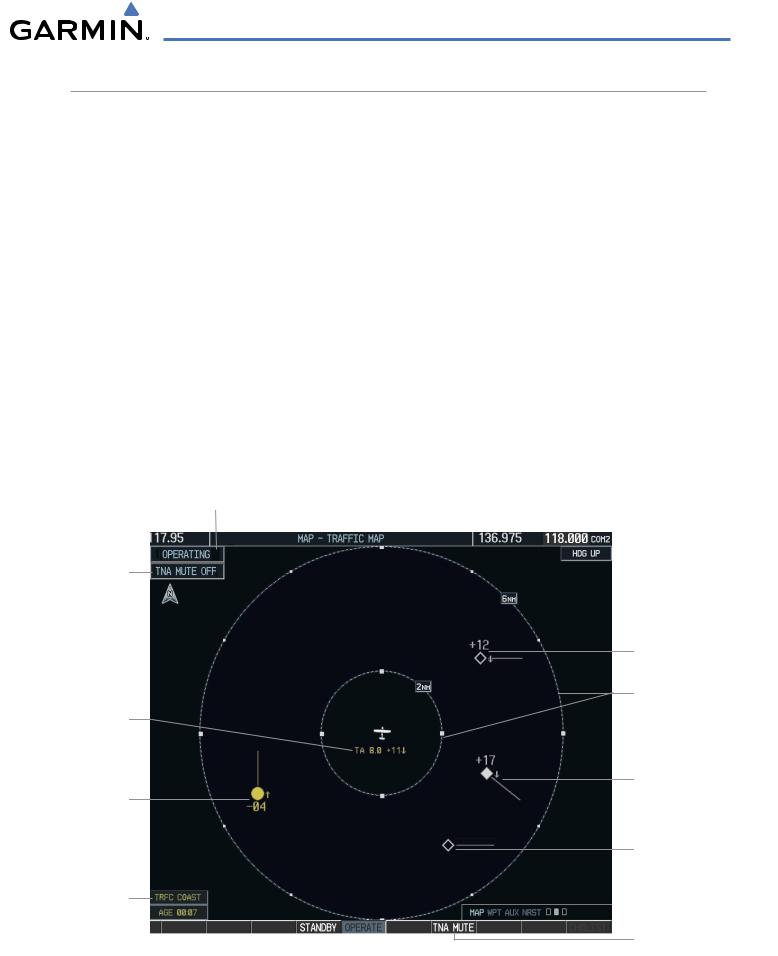
The Traffic Map Page is specialized to show surrounding TIS traffic data in relation to the aircraft’s current position and altitude, without clutter from the basemap. Aircraft orientation on this map is always heading up unless there is no valid heading. Map range is adjustable with the RANGE Knob from 2 to 12 nm, as indicated by the map range rings.
The traffic mode is annunciated in the upper left corner of the Traffic Map Page. When the aircraft is on the ground, TIS automatically enters Standby Mode. Once the aircraft is airborne, TIS switches from Standby to Operating Mode and the G1000 begins to display traffic information. Refer to the System Status discussion for more information.
Displaying traffic on the Traffic Map Page:
1)Turn the large FMS Knob to select the Map Page Group.
2)Turn the small FMS Knob to select the Traffic Map Page.
3)Confirm TIS is in Operating Mode:
Press the OPERATE Softkey to begin displaying traffic.
Or:
a)Press the MENU Key.
b)Select ‘Operate Mode’ (shown if TIS is in Standby Mode) and press the ENT Key.
Traffic Mode Annunciation
“TIS Not Available”
Voice Alert Status
“Non-Bearing” Traffic
(System Unable to
Determine Bearing)
Distance is 8.0 nm,
1100’ Above,
Descending
Traffic Advisory
400’ Below, Climbing
Traffic Status Banner
Figure 6-68 Traffic Map Page
Non-Threat Traffic
Range Marking Rings
Proximity Advisory
1700’ Above, Descending
Non-Threat Traffic
Select to Mute “TIS Not Available” Voice Alert
190-00498-03 Rev.A |
Garmin G1000 Pilot’s Guide for Cessna Nav III |
6-51 |