

FLIGHT MANAGEMENT
5.3 WAYPOINTS
Waypoints are predetermined geographical positions (internal database) or pilot-entered positions, and are used for all phases of flight planning and navigation.
Communication and navigation frequencies can be tuned “automatically” from various Waypoint Information (WPT) pages, Nearest (NRST) pages, and the Nearest Airports Window (on PFD). This auto-tuning feature simplifies frequency entry over manual tuning. Refer to the CNS and Audio Panel section for details on autotuning.
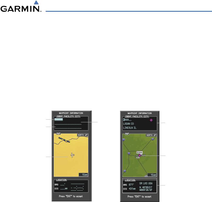
Waypoints can be selected by entering the ICAO identifier, entering the name of the facility, or by entering the city name. See the System Overview section for detailed instructions on entering data in the G1000. As a waypoint identifier, facility name, or location is entered, the G1000’s Spell’N’Find™ feature scrolls through the database, displaying those waypoints matching the characters which have been entered to that point. A direct-to navigation leg to the selected waypoint can be initiated by pressing the Direct-to Key on any of the waypoint pages.
Identifier Entry Field |
Facility |
|
- Waypoint Identifier |
|
|
||
|
|
- Type (symbol) |
|
City Entry Field |
Entry Field |
|
|
|
- Facility Name |
||
|
|
|
|
|
|
|
- City |
Map Area Showing |
Entered Waypoint on |
|
Map |
||
Entered Waypoint |
||
|
Waypoint Location
Figure 5-29 Waypoint Information Window
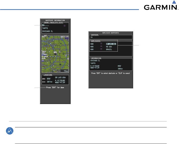
If duplicate entries exist for the entered facility name or location, additional entries may be viewed by continuing to turn the small FMS Knob during the selection process. If duplicate entries exist for an identifier, a Duplicate Waypoints Window is displayed when the ENT Key is pressed.
190-00498-03 Rev.A |
Garmin G1000 Pilot’s Guide for Cessna Nav III |
5-29 |
FLIGHT MANAGEMENT
Identifier with
Duplicates
Duplicate
Waypoints
Duplicate Message
Figure 5-30 Waypoint Information Window - Duplicate Identifier
AIRPORTS
NOTE: ‘North Up’ orientation on the Airport Information Page cannot be changed; the pilot needs to be aware of proper orientation if the Navigation Map orientation is different from theAirport Information Page Map.
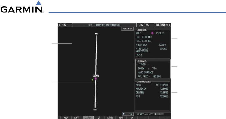
The Airport Information Page is the first page in WPT group and allows the pilot to view airport information, load frequencies (COM, NAV, and lighting), review runways, and review instrument procedures that may be involved in the flight plan. See the Audio Panel and CNS Section for more information on loading frequencies (auto-tuning). After engine startup, the Airport Information Page defaults to the airport where the aircraft is located. After a flight plan has been loaded, it defaults to the destination airport. On a flight plan with multiple airports, it defaults to the airport which is the current active waypoint.
In addition to displaying a map of the currently selected airport and surrounding area, the Airport Information Page displays airport information in three boxes labeled ‘AIRPORT’, ‘RUNWAYS’, and ‘FREQUENCIES’. For airports with multiple runways, information for each runway is available.
5-30 |
Garmin G1000 Pilot’s Guide for Cessna Nav III |
190-00498-03 Rev.A |
FLIGHT MANAGEMENT
|
|
Airport Information |
Navigation Map |
|
- ID/Facility/City |
Showing Selected |
|
- Usage Type/Region |
Airport |
|
- Lat/Long/Elev |
|
|
- Fuel Available |
|
|
- Time Zone (UTC Offset) |
|
|
|
|
Runway Information |
|
|
- Designation |
|
|
- Length/Width/Surface |
Airport/Runway |
|
- Lighting Available |
|
||
|
|
|
Diagram |
|
|
|
|
COM/NAV Freq. Info. |
|
|
- Identification |
|
|
- Frequency |
|
|
- Availability |
|
|
- Additional Information |
|
|
Softkeys
Figure 5-31 Airport Information Page
The following descriptions and abbreviations are used on the Airport Information Page:
•Usage type: Public, Military, or Private
•Runway surface type: Hard, Turf, Sealed, Gravel, Dirt, Soft, Unknown, or Water
•Runway lighting type: No Lights, Part Time, Full Time, Unknown, or PCL Freq (for pilot-controlled lighting)
•COM Availability: TX (transmit only), RX (receive only), PT (part time), i (additional information available)
Selecting an airport for review by identifier, facility name, or location:
1)From the Airport Information Page, press the FMS Knob.
2)Use the FMS Knobs and enter an identifier, facility name, or location.
3)Press the ENT Key.
4)Press the FMS Knob to remove the cursor.
Selecting a runway:
1)With the Airport Information Page displayed, press the FMS Knob to activate the cursor.
2)Turn the large FMS Knob to place the cursor in the ‘RUNWAYS’ Box, on the runway designator.
3)Turn the small FMS Knob to display the desired runway (if more than one) for the selected airport.
4)To remove the flashing cursor, press the FMS Knob.
View a destination airport:
From the Airport Information Page press the MENU Key. Select ‘View Destination Airport’. The Destination Airport is displayed.
190-00498-03 Rev.A |
Garmin G1000 Pilot’s Guide for Cessna Nav III |
5-31 |
FLIGHT MANAGEMENT
The Airport Frequencies Box uses the descriptions and abbreviations listed in the following table:
Communication Frequencies |
Navigation Frequencies |
||
Approach * |
Control |
Pre-Taxi |
ILS |
Arrival * |
CTA * |
Radar |
LOC |
ASOS |
Departure * |
Ramp |
|
ATIS |
Gate |
Terminal * |
|
AWOS |
Ground |
TMA * |
|
Center |
Helicopter |
Tower |
|
Class B * |
Multicom |
TRSA * |
|
Class C * |
Other |
Unicom |
|
Clearance |
|
|
|
* May include Additional Information
Table 5-5 Airport Frequency Abbreviations
A departure, arrival, or approach can be loaded using the softkeys on the Airport Information Page. See the procedures section for details. METARs or TAFs applicable to the selected airport can be selected for display (see
the Hazard Avoidance section for details about weather.
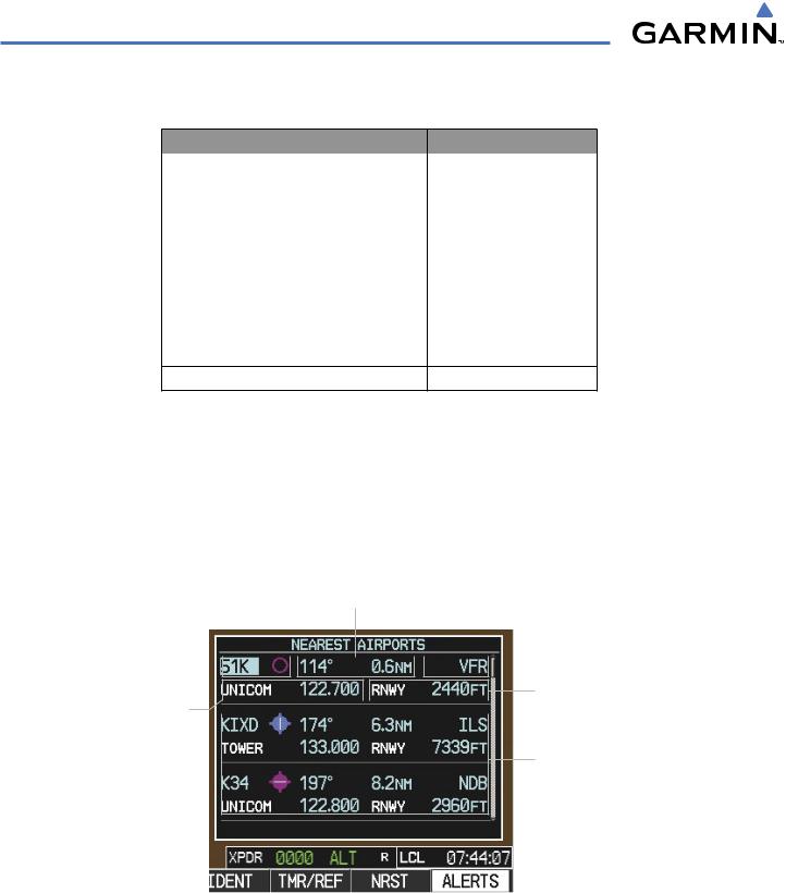
The G1000 provides a NRST Softkey on the PFD, which gives the pilot quick access to nearest airport information (very useful if an immediate need to land is required). The Nearest Airports Window displays a list of the 25 nearest airports (three entries can be displayed at one time). If there are more than three they are displayed in a scrollable list. If there are no nearest airports available, “NONE WITHIN 200NM” is displayed.
Bearing/Distance to Airport
Airport Identifier/


 Approach Available
Type
|
|
|
|
Length of Longest |
COM Freq. Info. |
|
|
|
Runway |
-Identification
-Frequency
Additional Airports (within 200 nm)
NRST Softkey
Figure 5-32 Nearest Airports Window on PFD
Pressing the ENT Key displays the PFD Airport Information Window for the highlighted airport. Pressing the ENT Key again returns to the Nearest Airports Window with the cursor on the next airport in the list.
5-32 |
Garmin G1000 Pilot’s Guide for Cessna Nav III |
190-00498-03 Rev.A |
FLIGHT MANAGEMENT
Continued presses of the ENT Key sequences through the information pages for all airports in the Nearest Airports list.:
Airport Information
-ID/Type/City
-Facility
Airport Information
- Usage/Time/Elev
- Region
Airport Information
- Lat/Long
Figure 5-33 Airport Information Window on PFD
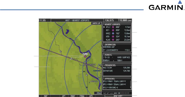
The Nearest Airports Page on the MFD is first in the group of NRST pages because of its potential use in the event of an in-flight emergency. In addition to displaying a map of the currently selected airport and surrounding area, the page displays nearest airport information in five boxes labeled ‘NEAREST AIRPORTS’, ‘INFORMATION’, ‘RUNWAYS’, ‘FREQUENCIES’, and ‘APPROACHES’.
The selected airport is indicated by a white arrow, and a dashed white line is drawn on the navigation map from the aircraft position to the nearest airport. Up to five nearest airports, one runway, up to three frequencies, and up to three approaches are visible at one time. If there are more than can be shown, each list can be scrolled. If there are no items for display in a boxed area, text indicating that fact is displayed. The currently selected airport remains in the list until it is unselected.
190-00498-03 Rev.A |
Garmin G1000 Pilot’s Guide for Cessna Nav III |
5-33 |
FLIGHT MANAGEMENT
Nearest Airport
Navigation Map
Showing Nearest
Airport
Window Selection

Softkeys
Figure 5-34 Nearest Airport Page
Nearest Airports
-ID/Type
-Bearing/Distance
Airport Information
- Facility/City/Elevation
Runway Information
-Designation/Surface
-Length/Width
COM/NAV Freq. Info.
-Identification
-Frequency
Approaches Available
LD APR Softkey (only available if an approach is highlighted)
Viewing information for a nearest airport on the PFD:
1)Press the NRST Softkey to display the Nearest Airports Window.
2)Highlight the airport identifier with the FMS Knob and press the ENT Key to display the Airport Information Window.
3)To return to the Nearest Airports Window press the ENT Key (with the cursor on ‘BACK’) or press the CLR Key. The cursor is now on the next airport in the nearest airports list. (Repeatedly pressing the ENT Key moves through the airport list, alternating between the Nearest Airports Window and the Airport Information Window.)
4)Press the CLR Key to close the PFD Nearest Airports Window.
Viewing information for a nearest airport on the MFD:
1)Turn the large FMS Knob to select the NRST page group.
2)Turn the small FMS Knob to select the Nearest Airports Page (it is the first page of the group, so it may already be selected. If there are no Nearest Airports available,“NONE WITHIN 200 NM” is displayed.
3)Press the APT Softkey; or press the FMS Knob; or press the MENU Key, highlight ‘Select Airport Window’ and press the ENT Key. The cursor is placed in the ‘NEARESTAIRPORTS’ Box. The first airport in the nearest airports list is highlighted.
4)Turn the FMS Knob to highlight the desired airport. (Pressing the ENT Key also moves to the next airport)
5)Press the FMS Knob to remove the flashing cursor.
5-34 |
Garmin G1000 Pilot’s Guide for Cessna Nav III |
190-00498-03 Rev.A |
FLIGHT MANAGEMENT
Viewing runway information for a specific airport:
1)With the Nearest Airports Page displayed, press the RNWY Softkey; or press the MENU Key, highlight ‘Select Runway Window’; and press the ENT Key. The cursor is placed in the ‘RUNWAYS’ Box.
2)Select the desired runway.
3)Press the FMS Knob to remove the flashing cursor.
See the Audio Panel and CNS Section for frequency selection and the Procedures section for approaches.
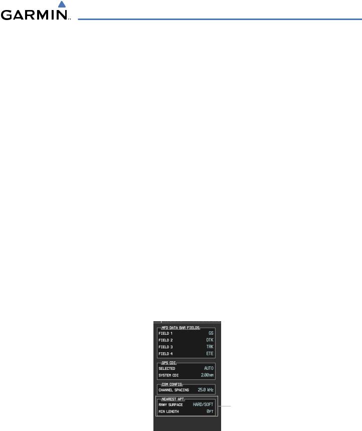
The Nearest Airports Box on the System Setup Page defines the minimum runway length and surface type used when determining the 25 nearest airports to display on the MFD Nearest Airports Page. A minimum runway length and/or surface type can be entered to prevent airports with small runways or runways that are not appropriately surfaced from being displayed. Default settings are 0 feet (or meters) for runway length and “ANY” for runway surface type.
Selecting nearest airport surface matching criteria:
1)Use the FMS Knob to select the System Setup Page.
2)Press the FMS Knob momentarily to activate the flashing cursor.
3)Turn the large FMS Knob to highlight the runway surface field in the Nearest Airports Box.
4)Turn the small FMS Knob to select the desired runway option (ANY, HARD ONLY, HARD/SOFT).
5)Press the ENT Key.
Selecting nearest airport minimum runway length matching criteria:
1)Use the FMS Knob to select the System Setup Page.
2)Press the FMS Knob momentarily to activate the flashing cursor.
3)Turn the large FMS Knob to highlight the minimum length field in the Nearest Airport Box.
4)Use the FMS Knob to enter the minimum runway length (zero to 99,999 feet) and press the ENT Key.
Nearest Airport Criteria
- Type of Runway Surface
- Minimum Runway Length
Figure 5-35 System Setup Page - Nearest Airport Selection Criteria
190-00498-03 Rev.A |
Garmin G1000 Pilot’s Guide for Cessna Nav III |
5-35 |