

- •Section 1 System Overview
- •1.1 System Description
- •1.2 Line Replaceable Units (LRU)
- •1.3 G1000 Controls
- •PFD/MFD Controls
- •Audio Panel Controls
- •1.4 Secure Digital (SD) Cards
- •1.5 System Power-up
- •1.6 System Operation
- •Normal Display Operation
- •Reversionary Display Operation
- •AHRS Operation
- •G1000 System Annunciations
- •Softkey Function
- •GPS Receiver Operation
- •1.7 Accessing G1000 Functionality
- •Menus
- •MFD Page Groups
- •MFD System Pages
- •1.8 Display Backlighting
- •Automatic Adjustment
- •Manual Adjustment
- •Section 2 Flight Instruments
- •2.1 Flight Instruments
- •Airspeed Indicator
- •Attitude Indicator
- •Altimeter
- •Vertical Speed Indicator (VSI)
- •Vertical Deviation
- •Horizontal Situation Indicator (HSI)
- •Course Deviation Indicator (CDI)
- •2.2 Supplemental Flight Data
- •Outside Air Temperature
- •Wind Data
- •Vertical Navigation (VNV) Indications
- •2.3 PFD Annunciations and Alerting Functions
- •G1000 System Alerting
- •Marker Beacon Annunciations
- •Traffic Annunciation
- •TAWS Annunciations
- •Altitude Alerting
- •Low Altitude Annunciation
- •Minimum Descent Altitude/Decision Height Alerting
- •2.4 Abnormal Operations
- •Abnormal GPS Conditions
- •Unusual Attitudes
- •Section 3 Engine Indication System (EIS)
- •3.1 Engine Display
- •3.2 Lean Display
- •Normally-aspirated Aircraft
- •Turbocharged Aircraft
- •3.3 System Display
- •Section 4 audio panel and CNS
- •4.1 Overview
- •MFD/PFD Controls and Frequency Display
- •Audio Panel Controls
- •4.2 COM Operation
- •COM Transceiver Selection and Activation
- •COM Transceiver Manual Tuning
- •Quick-Tuning and Activating 121.500 MHz
- •Auto-tuning the COM Frequency
- •Frequency Spacing
- •Automatic Squelch
- •Volume
- •4.3 NAV Operation
- •NAV Radio Selection and Activation
- •NAV Receiver Manual Tuning
- •Auto-tuning a NAV Frequency from the MFD
- •Marker Beacon Receiver
- •DME Tuning (Optional)
- •4.4 GTX 33 Mode S Transponder
- •Transponder Controls
- •Transponder Mode Selection
- •Entering a Transponder Code
- •IDENT Function
- •Flight ID Reporting
- •4.5 Additional Audio Panel Functions
- •Power-Up
- •Mono/Stereo Headsets
- •Speaker
- •Intercom
- •Passenger Address (PA) System
- •Clearance Recorder and Player
- •Entertainment Inputs
- •4.6 Audio Panel Preflight Procedure
- •4.7 Abnormal Operation
- •Stuck Microphone
- •COM Tuning Failure
- •Audio Panel Fail-Safe Operation
- •Reversionary Mode
- •Section 5 Flight Management
- •5.1 Introduction
- •Navigation Status Box
- •5.2 Using Map Displays
- •Map Orientation
- •Map Range
- •Map Panning
- •Measuring Bearing and Distance
- •Topography
- •Map Symbols
- •Airways
- •Track Vector
- •Wind Vector
- •Nav Range Ring
- •Fuel Range Ring
- •5.3 Waypoints
- •Airports
- •Intersections
- •NDBs
- •VORs
- •User Waypoints
- •5.4 Airspaces
- •5.5 Direct-to-Navigation
- •5.6 Flight Planning
- •Flight Plan Creation
- •Adding Waypoints To An Existing Flight Plan
- •Adding Airways to a Flight Plan
- •Adding Procedures To A Stored Flight Plan
- •Flight Plan Storage
- •Flight Plan Editing
- •Along Track Offsets
- •Parallel Track
- •Activating a Flight Plan Leg
- •Inverting a Flight Plan
- •Flight Plan Views
- •Closest Point of FPL
- •5.7 Vertical Navigation
- •Altitude Constraints
- •5.8 Procedures
- •Departures
- •Arrivals
- •Approaches
- •5.9 Trip Planning
- •Trip Planning
- •5.10 RAIM Prediction
- •5.11 Navigating a Flight Plan
- •5.12 Abnormal Operation
- •Section 6 Hazard Avoidance
- •6.1 XM Satellite Weather
- •Activating Services
- •Using XM Satellite Weather Products
- •6.2 WX-500 Stormscope (Optional)
- •Setting Up Stormscope on the Navigation Map
- •Selecting the Stormscope Page
- •6.3 Terrain Proximity
- •Displaying Terrain Proximity Data
- •Terrain Proximity Page
- •6.4 TAWs (Optional)
- •Displaying TAWS Data
- •TAWS Page
- •TAWS Alerts
- •System Status
- •6.5 Traffic Information Service (TIS)
- •Displaying TRAFFIC Data
- •Traffic Map Page
- •TIS Alerts
- •System Status
- •6.6 Traffic Advisory System (TAS) (Optional)
- •TAS Symbology
- •Operation
- •Altitude Display
- •Traffic Map Page Display Range
- •TAS Alerts
- •System Status
- •6.7 ADS-B Traffic (Optional)
- •Section 7 Automatic Flight Control System
- •7.2 Flight Director Operation
- •Activating the Flight Director
- •AFCS Status Box
- •Command Bars
- •Flight Director Modes
- •7.3 Vertical Modes
- •Pitch Hold Mode (PIT)
- •Selected Altitude capture Mode (ALTs)
- •Altitude hold mode (alt)
- •Vertical Speed Mode (VS)
- •Flight Level Change Mode (FLC)
- •Vertical Navigation Modes (VPTH, ALTV)
- •Glidepath Mode (GP) (waas only)
- •Glideslope Mode (GS)
- •Go Around (GA) Mode
- •7.4 Lateral Modes
- •Roll Hold Mode (ROL)
- •Heading Select Mode (HDG)
- •Navigation mode (GPS, VOR, LOC)
- •Approach mode (GPS, VAPP, LOC)
- •Backcourse Mode (BC)
- •7.5 Autopilot Operation
- •Engaging the Autopilot
- •Control Wheel Steering
- •Disengaging the Autopilot
- •7.6 Example Procedures
- •Departure
- •Intercepting a VOR Radial
- •Flying a Flight Plan/GPS Course
- •Descent
- •Approach
- •Go Around/Missed Approach
- •7.7 AFCS Annunciations and Alerts
- •AFCS Status Alerts
- •Overspeed Protection
- •Section 8 Additional Features
- •8.1 SafeTaxi
- •SafeTaxi Cycle Number and Revision
- •8.2 ChartView
- •ChartView Softkeys
- •Terminal Procedures Charts
- •Chart Options
- •Day/Night View
- •ChartView Cycle Number and Expiration Date
- •8.3 FliteCharts
- •FliteCharts Softkeys
- •Terminal Procedures Charts
- •Chart Options
- •Day/Night View
- •FliteCharts Cycle Number and Expiration Date
- •8.4 XM Radio Entertainment (Optional)
- •Activating XM Satellite Radio Services
- •Using XM Radio
- •Automatic Audio Muting
- •8.5 Scheduler
- •8.5 Abnormal Operation
- •Annunciations and Alerts
- •Alert Level Definitions
- •Nav III Aircraft Alerts
- •CO Guardian Messages
- •G1000 System Annunciations
- •Other G1000 Aural Alerts
- •G1000 System Message Advisories
- •AFCS Alerts
- •TAWS ALERTS
- •TAWS System Status Annunciations
- •SD Card Use
- •Jeppesen Databases
- •Garmin Databases
- •Glossary
- •Frequently Asked Questions
- •General TIS Information
- •Introduction
- •TIS vs. TAS/TCAS
- •TIS Limitations
- •Map Symbols
- •Index
HAZARD AVOIDANCE
TAWS ALERTS
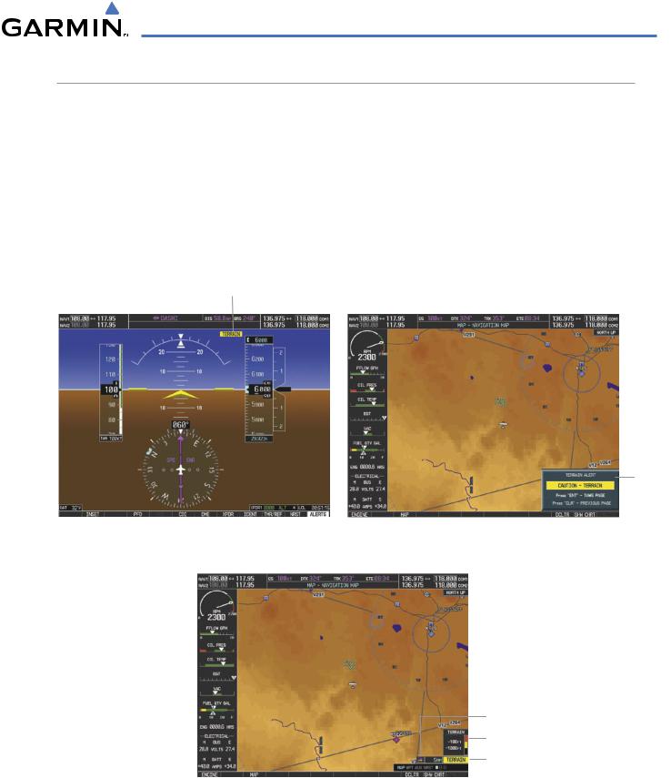
Alerts are issued when flight conditions meet parameters that are set within TAWS software algorithms. TAWS alerts typically employ a CAUTION or a WARNING alert severity level, or both. When an alert is issued, visual annunciations are displayed and aural alerts are simultaneously issued. Table 6-6 shows TAWS alert types with corresponding annunciations and aural messages.
When an alert is issued, annunciations appear on the PFD and MFD. The TAWS Alert Annunciation is shown to the upper left of the Altimeter on the PFD and below the Terrain Legend on the MFD. If the TAWS Page is not displayed at the time, a pop-up alert appears on the MFD. To acknowledge the pop-up alert:
•Press the CLR Key (returns to the currently viewed page), or
•Press the ENT Key (accesses the TAWS Page)
Alert Annunciation
Pop-up
Alert
Figure 6-57 TAWS Alert Annunciations
Terrain Display Enabled
Terrain Legend
Alert Annunciation
Figure 6-58 Navigation Map Page
(After TAWS Pop-up Alert Acknowledgment)
190-00498-03 Rev.A |
Garmin G1000 Pilot’s Guide for Cessna Nav III |
6-41 |

HAZARD AVOIDANCE
Alert Type |
PFD/MFDAlert |
MFD Pop-Up Alert |
Aural Message |
|
Annunciation |
||||
|
|
|
||
Excessive Descent Rate Warning |
|
|
“Pull Up” |
|
(EDR) |
|
|
||
|
|
|
||
Reduced Required Terrain |
|
* |
“Terrain Ahead, Pull Up;Terrain Ahead, Pull Up”* |
|
|
or |
or |
||
Clearance Warning (RTC) |
|
|||
|
|
“Terrain,Terrain; Pull Up, Pull Up” |
||
|
|
|
||
|
|
|
|
|
Imminent Terrain Impact |
|
* |
Terrain Ahead, Pull Up;Terrain Ahead, Pull Up’* |
|
|
or |
or |
||
Warning (ITI) |
|
|||
|
|
“Terrain,Terrain; Pull Up, Pull Up” |
||
|
|
|
||
|
|
|
|
|
Reduced Required Obstacle |
|
* |
“ObstacleAhead, Pull Up; ObstacleAhead, Pull Up”* |
|
|
or |
or |
||
Clearance Warning (ROC) |
|
|||
|
|
“Obstacle, Obstacle; Pull Up, Pull Up” |
||
|
|
|
||
|
|
|
|
|
Imminent Obstacle Impact |
|
* |
“ObstacleAhead, Pull Up; ObstacleAhead, Pull Up” |
|
|
or |
or |
||
Warning (IOI) |
|
|||
|
|
“Obstacle, Obstacle; Pull Up, Pull Up” |
||
|
|
|
||
|
|
|
|
|
Reduced Required Terrain |
|
* |
“Terrain Ahead;Terrain Ahead”* |
|
|
or |
or |
||
Clearance Caution (RTC) |
|
|||
|
|
“Caution,Terrain; Caution,Terrain” |
||
|
|
|
||
|
|
|
|
|
Imminent Terrain Impact Caution |
|
* |
“Terrain Ahead;Terrain Ahead”* |
|
|
or |
or |
||
(ITI) |
|
|||
|
|
“Caution,Terrain; Caution,Terrain” |
||
|
|
|
||
|
|
|
|
|
Reduced Required Obstacle |
|
* |
“Obstacle Ahead; Obstacle Ahead”* |
|
|
or |
or |
||
Clearance Caution (ROC) |
|
|||
|
|
“Caution, Obstacle; Caution, Obstacle” |
||
|
|
|
||
|
|
|
|
|
Imminent Obstacle Impact |
|
* |
“Obstacle Ahead; Obstacle Ahead”* |
|
|
or |
or |
||
Caution (IOI) |
|
|||
|
|
“Caution, Obstacle; Caution, Obstacle” |
||
|
|
|
||
|
|
|
|
|
Premature Descent Alert |
|
|
“Too Low,Terrain” |
|
Caution (PDA) |
|
|
||
|
|
|
||
Altitude Callout “500” |
None |
None |
“Five-Hundred” |
|
Excessive Descent Rate Caution |
|
|
“Sink Rate” |
|
(EDR) |
|
|
||
|
|
|
||
Negative Climb Rate Caution |
|
* |
“Don’t Sink”* |
|
|
or |
or |
||
(NCR) |
|
|||
|
|
“Too Low,Terrain” |
||
|
|
|
||
|
|
|
|
*Alerts with multiple messages are configurable at installation and are installation-dependent. Alerts for the default configuration are indicated with asterisks.
Table 6-6 TAWS Alerts Summary
6-42 |
Garmin G1000 Pilot’s Guide for Cessna Nav III |
190-00498-03 Rev.A |
HAZARD AVOIDANCE
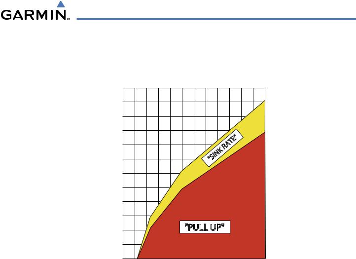
EXCESSIVE DESCENT RATE ALERT
The purpose of the Excessive Descent Rate (EDR) alert is to provide suitable notification when the aircraft is determined to be closing (descending) upon terrain at an excessive speed. Figure 6-59 shows the parameters for the alert as defined by TSO-C151b.
|
6000 |
|
|
|
|
|
|
5500 |
|
|
|
|
|
|
5000 |
|
|
|
|
|
(Feet) |
4500 |
|
|
|
|
|
4000 |
|
|
ATE" |
|
|
|
|
|
|
|
|
|
|
Terrain |
|
|
|
R |
|
|
3500 |
|
|
"SINK |
|
|
|
|
|
|
|
|
||
3000 |
|
|
|
|
|
|
Above |
|
|
|
|
|
|
2500 |
|
|
|
|
|
|
|
|
|
|
|
|
|
Height |
2000 |
|
|
|
|
|
1500 |
|
|
|
|
|
|
|
|
|
|
|
|
|
|
1000 |
|
"PULL UP" |
|
|
|
|
500 |
|
|
|
|
|
|
0 |
4000 |
6000 |
8000 |
10000 |
12000 |
|
2000 |
|||||
Descent Rate (FPM)
Figure 6-59 Excessive Descent Rate Alert Criteria
190-00498-03 Rev.A |
Garmin G1000 Pilot’s Guide for Cessna Nav III |
6-43 |

HAZARD AVOIDANCE
FORWARD LOOKING TERRAIN AVOIDANCE
Reduced Required Terrain Clearance (RTC) and Reduced Required Obstacle Clearance (ROC) alerts are issued when the aircraft flight path is above terrain, yet is projected to come within the minimum clearance values in Table 6-7. When an RTC alert is issued, a potential impact point is displayed on the TAWS Page.
Imminent Terrain Impact (ITI) and Imminent Obstacle Impact (IOI) alerts are issued when the aircraft is below the elevation of a terrain or obstacle cell in the aircraft’s projected path. ITI and IOI alerts are accompanied by a potential impact point displayed on the TAWS Page. The alert is annunciated when the projected vertical flight path is calculated to come within minimum clearance altitudes in Table 6-7.
Flight Phase |
Minimum Clearance Altitude (ft) |
||
Level Flight |
Descending |
||
|
|||
Enroute |
700 |
500 |
|
Terminal |
350 |
300 |
|
Approach |
150 |
100 |
|
Departure |
100 |
100 |
|
Table 6-7 FLTA Alert Minimum Terrain and Obstacle Clearance Values
During final approach, Forward Looking Terrain Avoidance (FLTA) alerts are automatically inhibited when the aircraft is below 200 feet AGL while within 0.5 nm of the approach runway or below 125 feet AGL while within 1.0 nm of the runway threshold.
6-44 |
Garmin G1000 Pilot’s Guide for Cessna Nav III |
190-00498-03 Rev.A |
HAZARD AVOIDANCE
PREMATURE DESCENT ALERTING
A Premature Descent Alert (PDA) is issued when the system detects that the aircraft is significantly below the normal approach path to a runway (Figure 6-60).
PDA alerting begins when the aircraft is within 15 nm of the destination airport and ends when the aircraft is either 0.5 nm from the runway threshold OR is at an altitude of 125 feet AGL while within 1.0 nm of the threshold. During the final descent, algorithms set a threshold for alerting based on speed, distance, and other parameters.
Height Above Terrain (Feet)
700
600
500
400
300
200 |
|
|
|
|
|
|
|
PDA Alerting Area |
|
|
|
||||
|
|
|
|
|
|
|
|
|
|
|
|
|
|
|
|
100 |
|
|
|
|
|
|
|
|
|
|
|
|
|
|
|
Runway |
1 |
2 |
3 |
4 |
5 |
6 |
7 |
8 |
9 |
10 |
11 |
12 |
13 |
14 |
15 |
Threshold |
|
|
|
Distance From Destination Airport (nm) |
|
|
|
|
|||||||
|
|
|
|
|
|
|
|
||||||||
Figure 6-60 PDA Alerting Threshold
PDA and FLTA aural and visual alerts can be manually inhibited. Discretion should be used when inhibiting TAWS and the system should be enable when appropriate. When TAWS is inhibited, the alert annunciation ‘TAWS INHB’ is shown on the PFD and MFD (Figure 6-61).
Figure 6-61 TAWS Alerting Disabled
(TAWS Inhibited) Annunciation
Inhibiting/enabling TAWS alerting:
1)Select the TAWS Page.
2)Press the MENU Key.
3)Select ‘Inhibit TAWS’ or ‘Enable TAWS’ (choice dependent on current state) and press the ENT Key.
If TAWS alerts are inhibited when the Final Approach Fix is the active waypoint in a GPS WAAS approach, a ‘LOW ALT’ annunciation may appear on the PFD next to the Altimeter if the current aircraft altitude is at least 164 feet below the prescribed altitude at the Final Approach Fix. See the Flight Instruments Section for details.
190-00498-03 Rev.A |
Garmin G1000 Pilot’s Guide for Cessna Nav III |
6-45 |
HAZARD AVOIDANCE
FIVE-HUNDRED AURAL ALERT
The purpose of the aural alert message “Five-hundred”is to provide an advisory alert that the aircraft is 500 feet above terrain. When the aircraft descends within 500 feet of terrain, the aural message “Five-hundred” is generated. There are no display annunciations or pop-up alerts that accompany the aural message.
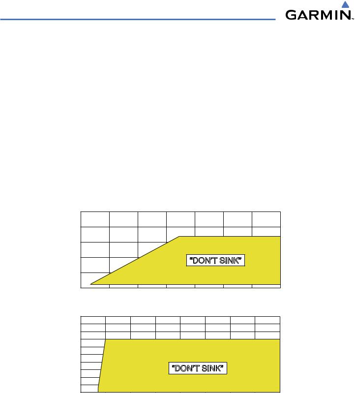
NEGATIVE CLIMB RATE AFTER TAKEOFF ALERT (NCR)
The Negative Climb Rate (NCR) After Takeoff alert (also referred to as “Altitude Loss After Takeoff”) provides alerts when the system determines the aircraft is losing altitude (closing upon terrain) after takeoff. The aural message “Don’t Sink” is given for NCR alerts, accompanied by an annunciation and a pop-up terrain alert on the display. NCR alerting is only active when departing from an airport and when the following conditions are met:
•Height above the terrain is less than 700 feet
•Distance from the departure airport is 2 nm or less
•Heading change from the departure heading is less than 110 degrees Figure 6-62 shows the NCR alerting parameters as defined by TSO-C151b.
(Feet) |
1000 |
|
|
|
|
|
|
|
|
800 |
|
|
|
|
|
|
|
||
Terrain |
|
|
|
|
|
|
|
||
600 |
|
|
|
|
|
|
|
||
|
|
|
|
|
|
|
|
||
Above |
400 |
|
|
|
“DON’T SINK” |
|
|
||
|
|
|
|
|
|
||||
200 |
|
|
|
|
|
|
|
||
Height |
|
|
|
|
|
|
|
||
0 |
20 |
40 |
60 |
80 |
100 |
120 |
140 |
||
|
|||||||||
Altitude Loss (Feet)
(Feet) |
1000 |
|
|
|
|
|
|
|
|
|
900 |
|
|
|
|
|
|
|
|
||
800 |
|
|
|
|
|
|
|
|
||
Terrain |
|
|
|
|
|
|
|
|
||
700 |
|
|
|
|
|
|
|
|
||
600 |
|
|
|
|
|
|
|
|
||
500 |
|
|
|
|
|
|
|
|
||
Above |
|
|
|
|
|
|
|
|
||
400 |
|
|
|
“DON’T SINK” |
|
|
|
|||
300 |
|
|
|
|
|
|
||||
200 |
|
|
|
|
|
|
|
|
||
Height |
|
|
|
|
|
|
|
|
||
100 |
|
|
|
|
|
|
|
|
||
0 |
500 |
1000 |
1500 |
2000 |
2500 |
3000 |
3500 |
4000 |
||
|
||||||||||
Sink Rate (Feet Per Minute)
Figure 6-62 Negative Climb Rate (NCR) Alert Criteria
6-46 |
Garmin G1000 Pilot’s Guide for Cessna Nav III |
190-00498-03 Rev.A |