

- •Section 1 System Overview
- •1.1 System Description
- •1.2 Line Replaceable Units (LRU)
- •1.3 G1000 Controls
- •PFD/MFD Controls
- •Audio Panel Controls
- •1.4 Secure Digital (SD) Cards
- •1.5 System Power-up
- •1.6 System Operation
- •Normal Display Operation
- •Reversionary Display Operation
- •AHRS Operation
- •G1000 System Annunciations
- •Softkey Function
- •GPS Receiver Operation
- •1.7 Accessing G1000 Functionality
- •Menus
- •MFD Page Groups
- •MFD System Pages
- •1.8 Display Backlighting
- •Automatic Adjustment
- •Manual Adjustment
- •Section 2 Flight Instruments
- •2.1 Flight Instruments
- •Airspeed Indicator
- •Attitude Indicator
- •Altimeter
- •Vertical Speed Indicator (VSI)
- •Vertical Deviation
- •Horizontal Situation Indicator (HSI)
- •Course Deviation Indicator (CDI)
- •2.2 Supplemental Flight Data
- •Outside Air Temperature
- •Wind Data
- •Vertical Navigation (VNV) Indications
- •2.3 PFD Annunciations and Alerting Functions
- •G1000 System Alerting
- •Marker Beacon Annunciations
- •Traffic Annunciation
- •TAWS Annunciations
- •Altitude Alerting
- •Low Altitude Annunciation
- •Minimum Descent Altitude/Decision Height Alerting
- •2.4 Abnormal Operations
- •Abnormal GPS Conditions
- •Unusual Attitudes
- •Section 3 Engine Indication System (EIS)
- •3.1 Engine Display
- •3.2 Lean Display
- •Normally-aspirated Aircraft
- •Turbocharged Aircraft
- •3.3 System Display
- •Section 4 audio panel and CNS
- •4.1 Overview
- •MFD/PFD Controls and Frequency Display
- •Audio Panel Controls
- •4.2 COM Operation
- •COM Transceiver Selection and Activation
- •COM Transceiver Manual Tuning
- •Quick-Tuning and Activating 121.500 MHz
- •Auto-tuning the COM Frequency
- •Frequency Spacing
- •Automatic Squelch
- •Volume
- •4.3 NAV Operation
- •NAV Radio Selection and Activation
- •NAV Receiver Manual Tuning
- •Auto-tuning a NAV Frequency from the MFD
- •Marker Beacon Receiver
- •DME Tuning (Optional)
- •4.4 GTX 33 Mode S Transponder
- •Transponder Controls
- •Transponder Mode Selection
- •Entering a Transponder Code
- •IDENT Function
- •Flight ID Reporting
- •4.5 Additional Audio Panel Functions
- •Power-Up
- •Mono/Stereo Headsets
- •Speaker
- •Intercom
- •Passenger Address (PA) System
- •Clearance Recorder and Player
- •Entertainment Inputs
- •4.6 Audio Panel Preflight Procedure
- •4.7 Abnormal Operation
- •Stuck Microphone
- •COM Tuning Failure
- •Audio Panel Fail-Safe Operation
- •Reversionary Mode
- •Section 5 Flight Management
- •5.1 Introduction
- •Navigation Status Box
- •5.2 Using Map Displays
- •Map Orientation
- •Map Range
- •Map Panning
- •Measuring Bearing and Distance
- •Topography
- •Map Symbols
- •Airways
- •Track Vector
- •Wind Vector
- •Nav Range Ring
- •Fuel Range Ring
- •5.3 Waypoints
- •Airports
- •Intersections
- •NDBs
- •VORs
- •User Waypoints
- •5.4 Airspaces
- •5.5 Direct-to-Navigation
- •5.6 Flight Planning
- •Flight Plan Creation
- •Adding Waypoints To An Existing Flight Plan
- •Adding Airways to a Flight Plan
- •Adding Procedures To A Stored Flight Plan
- •Flight Plan Storage
- •Flight Plan Editing
- •Along Track Offsets
- •Parallel Track
- •Activating a Flight Plan Leg
- •Inverting a Flight Plan
- •Flight Plan Views
- •Closest Point of FPL
- •5.7 Vertical Navigation
- •Altitude Constraints
- •5.8 Procedures
- •Departures
- •Arrivals
- •Approaches
- •5.9 Trip Planning
- •Trip Planning
- •5.10 RAIM Prediction
- •5.11 Navigating a Flight Plan
- •5.12 Abnormal Operation
- •Section 6 Hazard Avoidance
- •6.1 XM Satellite Weather
- •Activating Services
- •Using XM Satellite Weather Products
- •6.2 WX-500 Stormscope (Optional)
- •Setting Up Stormscope on the Navigation Map
- •Selecting the Stormscope Page
- •6.3 Terrain Proximity
- •Displaying Terrain Proximity Data
- •Terrain Proximity Page
- •6.4 TAWs (Optional)
- •Displaying TAWS Data
- •TAWS Page
- •TAWS Alerts
- •System Status
- •6.5 Traffic Information Service (TIS)
- •Displaying TRAFFIC Data
- •Traffic Map Page
- •TIS Alerts
- •System Status
- •6.6 Traffic Advisory System (TAS) (Optional)
- •TAS Symbology
- •Operation
- •Altitude Display
- •Traffic Map Page Display Range
- •TAS Alerts
- •System Status
- •6.7 ADS-B Traffic (Optional)
- •Section 7 Automatic Flight Control System
- •7.2 Flight Director Operation
- •Activating the Flight Director
- •AFCS Status Box
- •Command Bars
- •Flight Director Modes
- •7.3 Vertical Modes
- •Pitch Hold Mode (PIT)
- •Selected Altitude capture Mode (ALTs)
- •Altitude hold mode (alt)
- •Vertical Speed Mode (VS)
- •Flight Level Change Mode (FLC)
- •Vertical Navigation Modes (VPTH, ALTV)
- •Glidepath Mode (GP) (waas only)
- •Glideslope Mode (GS)
- •Go Around (GA) Mode
- •7.4 Lateral Modes
- •Roll Hold Mode (ROL)
- •Heading Select Mode (HDG)
- •Navigation mode (GPS, VOR, LOC)
- •Approach mode (GPS, VAPP, LOC)
- •Backcourse Mode (BC)
- •7.5 Autopilot Operation
- •Engaging the Autopilot
- •Control Wheel Steering
- •Disengaging the Autopilot
- •7.6 Example Procedures
- •Departure
- •Intercepting a VOR Radial
- •Flying a Flight Plan/GPS Course
- •Descent
- •Approach
- •Go Around/Missed Approach
- •7.7 AFCS Annunciations and Alerts
- •AFCS Status Alerts
- •Overspeed Protection
- •Section 8 Additional Features
- •8.1 SafeTaxi
- •SafeTaxi Cycle Number and Revision
- •8.2 ChartView
- •ChartView Softkeys
- •Terminal Procedures Charts
- •Chart Options
- •Day/Night View
- •ChartView Cycle Number and Expiration Date
- •8.3 FliteCharts
- •FliteCharts Softkeys
- •Terminal Procedures Charts
- •Chart Options
- •Day/Night View
- •FliteCharts Cycle Number and Expiration Date
- •8.4 XM Radio Entertainment (Optional)
- •Activating XM Satellite Radio Services
- •Using XM Radio
- •Automatic Audio Muting
- •8.5 Scheduler
- •8.5 Abnormal Operation
- •Annunciations and Alerts
- •Alert Level Definitions
- •Nav III Aircraft Alerts
- •CO Guardian Messages
- •G1000 System Annunciations
- •Other G1000 Aural Alerts
- •G1000 System Message Advisories
- •AFCS Alerts
- •TAWS ALERTS
- •TAWS System Status Annunciations
- •SD Card Use
- •Jeppesen Databases
- •Garmin Databases
- •Glossary
- •Frequently Asked Questions
- •General TIS Information
- •Introduction
- •TIS vs. TAS/TCAS
- •TIS Limitations
- •Map Symbols
- •Index

AUTOMATIC FLIGHT CONTROL SYSTEM
APPROACH
Flying an ILS approach:
1)Transition from GPS Navigation Mode to Heading Select Mode.
a)Select the Runway 35L ILS approach for KCOS and select ‘VECTORS’ for the transition. Load and activate the approach into the flight plan.
b)Use the HDG Knob to set the Selected Heading after getting vectors from ATC.
c)Press the HDG Key. The autopilot turns the aircraft to the desired heading.
d)Use Heading Select Mode to comply with ATC vectors as requested.
2)Arm LOC Approach and Glideslope modes.
a)Ensure the appropriate localizer frequency is tuned.
b)Press the APR Key when cleared for approach to arm Approach and Glideslope modes. ‘LOC’ and ‘GS’ appear in white as armed mode annunciations.
c)The navigation source automatically switches to LOC. After this switch occurs,the localizer signal can be captured and the flight director determine when to begin the turn to intercept the final approach course. The flight director now provides guidance to the missed approach point.
3)There are two options available at this point, as the autopilot flies the ILS approach:
• Push the AP DISC Switch at the decision |
• Use the GA Switch to execute a missed |
height and land the aircraft. |
approach. |
KCOS |
|
3
G |
LOC |
|
S |
|
|
M |
A |
|
ode |
||
PR/ |
||
|
PETEY
2
HDG
Mode
PYNON  1
1
Mode VNA GPS
Figure 7-37 ILS Approach to KCOS
190-00498-03 Rev.A |
Garmin G1000 Pilot’s Guide for Cessna Nav III |
7-41 |
AUTOMATIC FLIGHT CONTROL SYSTEM
 NOTE: Support for WAAS precision approaches is available only in installations with GIA 63W IAUs when WAAS is available.
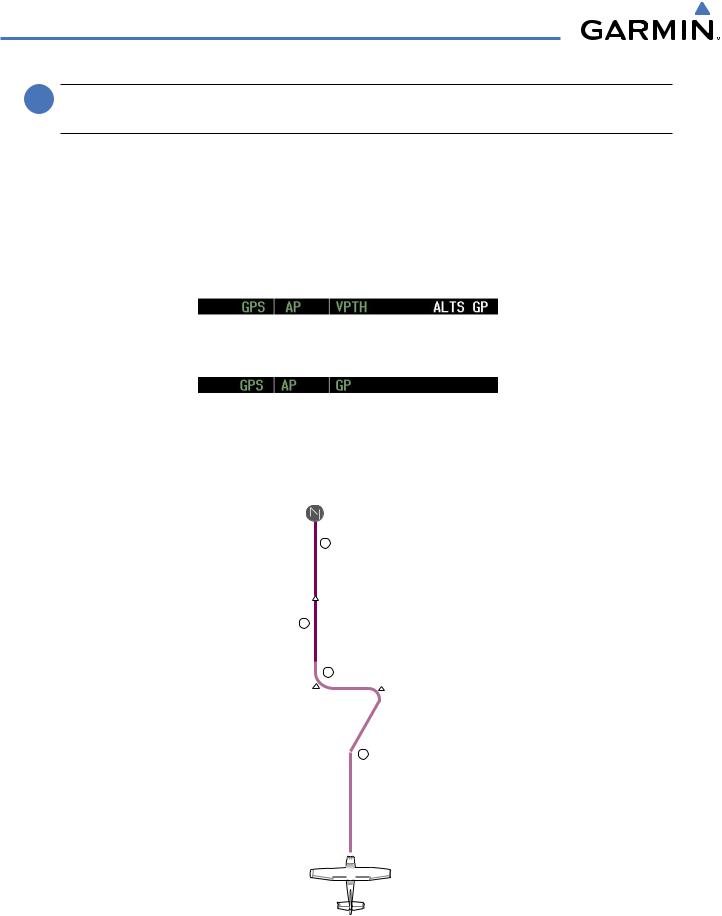
Flying a RNAV GPS approach with vertical guidance:
1)Arm flight director modes for a RNAV GPS approach with vertical guidance:
a)Make sure the navigation source is set to GPS (use CDI Softkey to change navigation source).
b)Select the Runway 35R LPV approach for KCOS. Load and activate the approach into the flight plan.
2)Press the APR Key once clearance for approach has been received. GPS Approach Mode is activated and Glidepath Mode is armed.
3)Once the glidepath is captured, Glidepath Mode becomes active. The flight director now provides guidance to the missed approach point.
4)There are two options available at this point, as the autopilot flies the approach:
• Push the AP DISC Switch at the Decision |
• Use the GA Switch to execute a missed |
height and land the aircraft. |
approach. |
KCOS |
|
CEGI
3
4
G |
GPS |
P |
|
M |
APR/ |
ode |
2
FALU |
HABUK |
|
PYNON 1
1
Mode VNA GPS
Figure 7-38 LPV Approach to KCOS
7-42 |
Garmin G1000 Pilot’s Guide for Cessna Nav III |
190-00498-03 Rev.A |
AUTOMATIC FLIGHT CONTROL SYSTEM
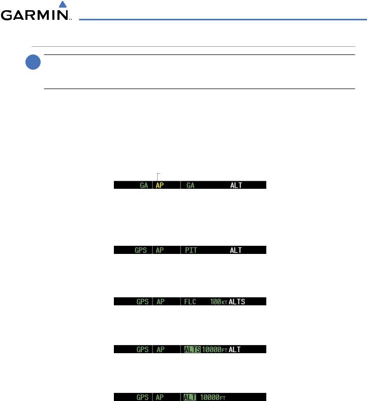
GO AROUND/MISSED APPROACH
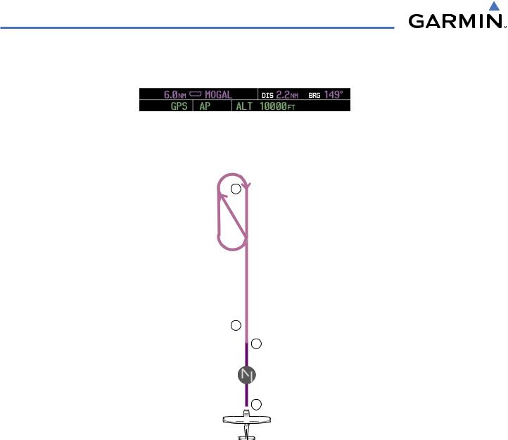
 NOTE: As a result of calculations performed by the system while flying the holding pattern, the display may re-size automatically and the aircraft may not precisely track the holding pattern as depicted on the PFD and MFD.
Flying a missed approach:
1)Push the GA Switch at the Decision height and apply go around power to execute a missed approach. The flight director Command Bars establish a nose-up climb to follow. If flying an ILS or LOC approach the CDI also switches to GPS as the navigation source.
Note that when the GA Switch is pushed, the missed approach is activated and the autopilot disconnects, indicated by the ‘AP’ annunciation flashing yellow for 5 seconds and the autopilot disconnect aural alert.
Flashes 5 sec
2)Start the climb to the prescribed altitude in the published Missed Approach Procedure (in this case, 10,000 ft).
a)Press the AP Key to re-engage the autopilot.
b)Press the NAV Key to have the autopilot fly to the hold.
3)Use the ALT Knob to set a Selected Altitude to hold.
To hold the current airspeed during the climb, press the FLC Key.
As the aircraft nears the Selected Altitude, the flight director transitions to Selected Altitude Capture Mode, indicated by the green ‘ALTS’ annunciation flashing for up to 10 seconds.
The green ‘ALT’ annunciation flashes for up to 10 seconds upon reaching 50 feet from the SelectedAltitude; the autopilot transitions to Altitude Hold Mode and levels the aircraft.
190-00498-03 Rev.A |
Garmin G1000 Pilot’s Guide for Cessna Nav III |
7-43 |
AUTOMATIC FLIGHT CONTROL SYSTEM
4)The autopilot flies the holding pattern after the missed approach is activated. Annunciations are displayed in the Navigation Status Box, above the AFCS Status Box.
 MOGAL
MOGAL
NAV GPS
Mode 3
2
KCOS GA
Mode
1
Figure 7-39 Go Around/Missed Approach
7-44 |
Garmin G1000 Pilot’s Guide for Cessna Nav III |
190-00498-03 Rev.A |