

- •Section 1 System Overview
- •1.1 System Description
- •1.2 Line Replaceable Units (LRU)
- •1.3 G1000 Controls
- •PFD/MFD Controls
- •Audio Panel Controls
- •1.4 Secure Digital (SD) Cards
- •1.5 System Power-up
- •1.6 System Operation
- •Normal Display Operation
- •Reversionary Display Operation
- •AHRS Operation
- •G1000 System Annunciations
- •Softkey Function
- •GPS Receiver Operation
- •1.7 Accessing G1000 Functionality
- •Menus
- •MFD Page Groups
- •MFD System Pages
- •1.8 Display Backlighting
- •Automatic Adjustment
- •Manual Adjustment
- •Section 2 Flight Instruments
- •2.1 Flight Instruments
- •Airspeed Indicator
- •Attitude Indicator
- •Altimeter
- •Vertical Speed Indicator (VSI)
- •Vertical Deviation
- •Horizontal Situation Indicator (HSI)
- •Course Deviation Indicator (CDI)
- •2.2 Supplemental Flight Data
- •Outside Air Temperature
- •Wind Data
- •Vertical Navigation (VNV) Indications
- •2.3 PFD Annunciations and Alerting Functions
- •G1000 System Alerting
- •Marker Beacon Annunciations
- •Traffic Annunciation
- •TAWS Annunciations
- •Altitude Alerting
- •Low Altitude Annunciation
- •Minimum Descent Altitude/Decision Height Alerting
- •2.4 Abnormal Operations
- •Abnormal GPS Conditions
- •Unusual Attitudes
- •Section 3 Engine Indication System (EIS)
- •3.1 Engine Display
- •3.2 Lean Display
- •Normally-aspirated Aircraft
- •Turbocharged Aircraft
- •3.3 System Display
- •Section 4 audio panel and CNS
- •4.1 Overview
- •MFD/PFD Controls and Frequency Display
- •Audio Panel Controls
- •4.2 COM Operation
- •COM Transceiver Selection and Activation
- •COM Transceiver Manual Tuning
- •Quick-Tuning and Activating 121.500 MHz
- •Auto-tuning the COM Frequency
- •Frequency Spacing
- •Automatic Squelch
- •Volume
- •4.3 NAV Operation
- •NAV Radio Selection and Activation
- •NAV Receiver Manual Tuning
- •Auto-tuning a NAV Frequency from the MFD
- •Marker Beacon Receiver
- •DME Tuning (Optional)
- •4.4 GTX 33 Mode S Transponder
- •Transponder Controls
- •Transponder Mode Selection
- •Entering a Transponder Code
- •IDENT Function
- •Flight ID Reporting
- •4.5 Additional Audio Panel Functions
- •Power-Up
- •Mono/Stereo Headsets
- •Speaker
- •Intercom
- •Passenger Address (PA) System
- •Clearance Recorder and Player
- •Entertainment Inputs
- •4.6 Audio Panel Preflight Procedure
- •4.7 Abnormal Operation
- •Stuck Microphone
- •COM Tuning Failure
- •Audio Panel Fail-Safe Operation
- •Reversionary Mode
- •Section 5 Flight Management
- •5.1 Introduction
- •Navigation Status Box
- •5.2 Using Map Displays
- •Map Orientation
- •Map Range
- •Map Panning
- •Measuring Bearing and Distance
- •Topography
- •Map Symbols
- •Airways
- •Track Vector
- •Wind Vector
- •Nav Range Ring
- •Fuel Range Ring
- •5.3 Waypoints
- •Airports
- •Intersections
- •NDBs
- •VORs
- •User Waypoints
- •5.4 Airspaces
- •5.5 Direct-to-Navigation
- •5.6 Flight Planning
- •Flight Plan Creation
- •Adding Waypoints To An Existing Flight Plan
- •Adding Airways to a Flight Plan
- •Adding Procedures To A Stored Flight Plan
- •Flight Plan Storage
- •Flight Plan Editing
- •Along Track Offsets
- •Parallel Track
- •Activating a Flight Plan Leg
- •Inverting a Flight Plan
- •Flight Plan Views
- •Closest Point of FPL
- •5.7 Vertical Navigation
- •Altitude Constraints
- •5.8 Procedures
- •Departures
- •Arrivals
- •Approaches
- •5.9 Trip Planning
- •Trip Planning
- •5.10 RAIM Prediction
- •5.11 Navigating a Flight Plan
- •5.12 Abnormal Operation
- •Section 6 Hazard Avoidance
- •6.1 XM Satellite Weather
- •Activating Services
- •Using XM Satellite Weather Products
- •6.2 WX-500 Stormscope (Optional)
- •Setting Up Stormscope on the Navigation Map
- •Selecting the Stormscope Page
- •6.3 Terrain Proximity
- •Displaying Terrain Proximity Data
- •Terrain Proximity Page
- •6.4 TAWs (Optional)
- •Displaying TAWS Data
- •TAWS Page
- •TAWS Alerts
- •System Status
- •6.5 Traffic Information Service (TIS)
- •Displaying TRAFFIC Data
- •Traffic Map Page
- •TIS Alerts
- •System Status
- •6.6 Traffic Advisory System (TAS) (Optional)
- •TAS Symbology
- •Operation
- •Altitude Display
- •Traffic Map Page Display Range
- •TAS Alerts
- •System Status
- •6.7 ADS-B Traffic (Optional)
- •Section 7 Automatic Flight Control System
- •7.2 Flight Director Operation
- •Activating the Flight Director
- •AFCS Status Box
- •Command Bars
- •Flight Director Modes
- •7.3 Vertical Modes
- •Pitch Hold Mode (PIT)
- •Selected Altitude capture Mode (ALTs)
- •Altitude hold mode (alt)
- •Vertical Speed Mode (VS)
- •Flight Level Change Mode (FLC)
- •Vertical Navigation Modes (VPTH, ALTV)
- •Glidepath Mode (GP) (waas only)
- •Glideslope Mode (GS)
- •Go Around (GA) Mode
- •7.4 Lateral Modes
- •Roll Hold Mode (ROL)
- •Heading Select Mode (HDG)
- •Navigation mode (GPS, VOR, LOC)
- •Approach mode (GPS, VAPP, LOC)
- •Backcourse Mode (BC)
- •7.5 Autopilot Operation
- •Engaging the Autopilot
- •Control Wheel Steering
- •Disengaging the Autopilot
- •7.6 Example Procedures
- •Departure
- •Intercepting a VOR Radial
- •Flying a Flight Plan/GPS Course
- •Descent
- •Approach
- •Go Around/Missed Approach
- •7.7 AFCS Annunciations and Alerts
- •AFCS Status Alerts
- •Overspeed Protection
- •Section 8 Additional Features
- •8.1 SafeTaxi
- •SafeTaxi Cycle Number and Revision
- •8.2 ChartView
- •ChartView Softkeys
- •Terminal Procedures Charts
- •Chart Options
- •Day/Night View
- •ChartView Cycle Number and Expiration Date
- •8.3 FliteCharts
- •FliteCharts Softkeys
- •Terminal Procedures Charts
- •Chart Options
- •Day/Night View
- •FliteCharts Cycle Number and Expiration Date
- •8.4 XM Radio Entertainment (Optional)
- •Activating XM Satellite Radio Services
- •Using XM Radio
- •Automatic Audio Muting
- •8.5 Scheduler
- •8.5 Abnormal Operation
- •Annunciations and Alerts
- •Alert Level Definitions
- •Nav III Aircraft Alerts
- •CO Guardian Messages
- •G1000 System Annunciations
- •Other G1000 Aural Alerts
- •G1000 System Message Advisories
- •AFCS Alerts
- •TAWS ALERTS
- •TAWS System Status Annunciations
- •SD Card Use
- •Jeppesen Databases
- •Garmin Databases
- •Glossary
- •Frequently Asked Questions
- •General TIS Information
- •Introduction
- •TIS vs. TAS/TCAS
- •TIS Limitations
- •Map Symbols
- •Index

AUTOMATIC FLIGHT CONTROL SYSTEM
7.5 AUTOPILOT OPERATION
 NOTE: Refer to the POH for specific instructions regarding emergency procedures.
The autopilot operates flight control surface servos to provide automatic flight control. Pitch and roll commands are provided to the servos, based on the active flight director modes. The autopilot uses pitch and roll rates to stabilize the aircraft attitude during upsets and flight director maneuvers. Flight director commands are rateand attitude-limited, combined with pitch and roll damper control, and sent to the pitch and roll servo motors.
Pitch autotrim provides trim commands to the pitch trim servo to relieve any sustained effort required by the pitch servo. The pitch servo measures the output effort (torque) and provides this signal to the pitch trim servo. The pitch trim servo commands the motor to reduce the average pitch servo effort.
When the autopilot is not engaged, the pitch trim servo may be used to provide manual electric trim (MET). This allows the aircraft to be trimmed using a control wheel switch rather than the trim wheel. Manual trim commands are generated with the MET Switch. Trim speeds are scheduled with airspeed to provide more consistent response.
Servo motor control limits the maximum servo speed and torque. The servo mounts are equipped with slipclutches set to certain values. This allows the servos to be overridden in case of an emergency.
ENGAGING THE AUTOPILOT
 NOTE: Autopilot engagement/disengagement is not equivalent to servo engagement/disengagement. Use the CWS Button to disengage the pitch and roll servos while the autopilot remains active.
WhentheAPKeyispressed,theautopilotandflightdirector(ifnotalreadyengaged)areactivated. Engagement is indicated by a green ‘AP’ annunciation in the center of the AFCS Status Box. The flight director engages in Pitch and Roll Hold modes when initially activated.
Autopilot
Engaged
Figure 7-26 Autopilot and Yaw Damper Engaged
7-30 |
Garmin G1000 Pilot’s Guide for Cessna Nav III |
190-00498-03 Rev.A |
AUTOMATIC FLIGHT CONTROL SYSTEM
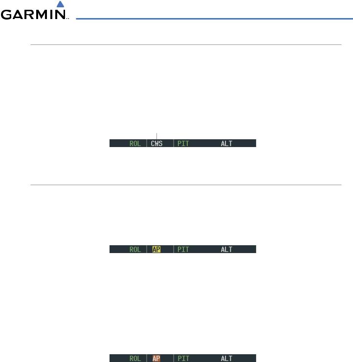
CONTROL WHEEL STEERING
During autopilot operation, the aircraft may be hand-flown without disengaging the autopilot. Pressing and holding the CWS Button disengages the pitch and roll servos from the flight control surfaces and allows the aircraft to be hand-flown. At the same time, the flight director is synchronized to the aircraft attitude during the maneuver. The ‘AP’ annunciation is temporarily replaced by ‘CWS’ in white for the duration of CWS maneuvers.
In most scenarios, releasing the CWS Button reengages the autopilot with a new reference. Refer to the flight director modes section for CWS behavior in each mode.
Control Wheel Steering
Figure 7-27 CWS Annunciation
DISENGAGING THE AUTOPILOT
The autopilot is manually disengaged by pushing the AP DISC Switch, GA Switch or the AP Key on the MFD. Manual disengagement is indicated by a five-second flashing yellow ‘AP’ annunciation and a twosecond autopilot disconnect aural alert. After manual disengagement, the autopilot disconnect aural alert may be cancelled by pushing the AP DISC or MET Switch (AP DISC Switch also cancels the flashing ‘AP’ annunciation).
Figure 7-28 Manual Autopilot Disengagement
Automatic autopilot disengagement is indicated by a flashing red ‘AP’ annunciation and by the autopilot disconnect aural alert, which continue until acknowledged by pushing the AP DISC or MET Switch. Automatic disengagement occurs due to:
• System failure |
• Invalid sensor data |
•Inability to compute default flight director modes (FD also disengages automatically)
Figure 7-29 Automatic Autopilot Disengagement
190-00498-03 Rev.A |
Garmin G1000 Pilot’s Guide for Cessna Nav III |
7-31 |