


FLIGHT INSTRUMENTS
A magenta Altitude Trend Vector extends up or down the left of the altitude tape, the end resting at the approximate altitude to be reached in 6 seconds at the current vertical speed. The trend vector is not shown if altitude remains constant or if data needed for calculation is not available due to a system failure.
The barometric pressure setting is displayed below the Altimeter in inches of mercury (in Hg) or hectopascals (hPa) when metric units are selected. Adjusting the altimeter barometric setting creates discontinuities in VNV vertical deviation, moving the descent path. For large adjustments, it may take several minutes for the aircraft to re-establish on the descent path. If the change is made while nearing a waypoint with a VNV Target Altitude, the aircraft may not re-establish on the descent path in time to meet the vertical constraint.
Selecting the Altimeter barometric pressure setting:
Turn the BARO (outer) Knob to select the desired setting.
Selecting standard barometric pressure (29.92 in Hg):
1)Press the PFD Softkey.
2)Press the STD BARO Softkey.
Changing altimeter barometric pressure setting units:
1)Press the PFD Softkey to display the second-level softkeys.
2)Press the ALT UNIT Softkey.
3)Press the IN Softkey to display the barometric pressure setting in inches of mercury (in Hg).
Or, press the HPA Softkey to display the barometric pressure setting in hectopascals (hPa; see Figure 2-10).
4)Press the BACK Softkey twice to return to the top-level softkeys.
VERTICAL SPEED INDICATOR (VSI)
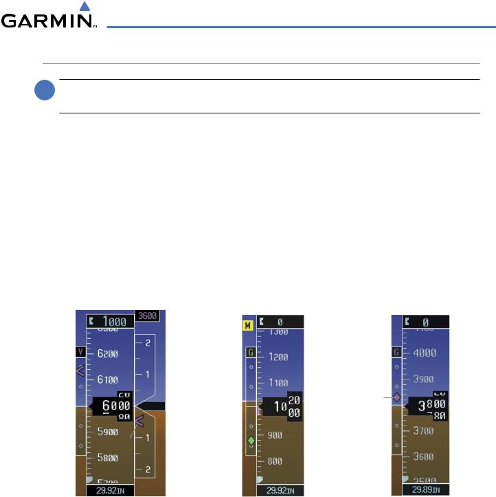
The Vertical Speed Indicator (VSI, Figure 2-11) displays the aircraft vertical speed using a non-moving tape labeled at 1000 and 2000 fpm with minor tick marks every 500 fpm. The current vertical speed is displayed in the pointer along the tape. Digits appear in the pointer when the climb or descent rate is greater than 100 fpm. If the rate of ascent/descent exceeds 2000 fpm, the pointer appears at the corresponding edge of the tape and the rate appears inside the pointer.
A magenta chevron bug is displayed as the Required Vertical Speed Indication (RVSI; see Figure 2-11) for reaching a VNV Target Altitude once the “TOD [Top of Descent] within 1 minute” alert has been generated. See the Flight Management section for details on VNV features, and refer to Section 2.2, Supplemental Flight Data, for more information about VNV indications on the PFD.
2-8 |
Garmin G1000 Pilot’s Guide for Cessna Nav III |
190-00498-03 Rev.A |
FLIGHT INSTRUMENTS
VERTICAL DEVIATION
 NOTE: The Glidepath Indicator is only shown for aircraft with GIA 63W Integrated Avionics Units when WAAS is available.
The Vertical Deviation Indicator (VDI; Figure 2-11) uses a magenta chevron to indicate the baro-VNV vertical deviation when Vertical Navigation (VNV) is being used; the VDI appears in conjunction with the “TOD within 1 minute” alert. Full-scale deflection (two dots) is 1000 feet. The VDI is removed from the display if vertical deviation becomes invalid. See the Flight Management section for details on VNV features, and refer to Section 2.2, Supplemental Flight Data, for more information about VNV indications on the PFD.
The Glideslope Indicator (Figure 2-12) appears to the left of the Altimeter whenever an ILS frequency is tuned in the active NAV field. A green diamond acts as the Glideslope Indicator, like a glideslope needle on a conventional indicator. If a localizer frequency is tuned and there is no glideslope, “NO GS” is annunciated.
The glidepath is analogous to the glideslope for GPS approaches supporting WAAS vertical guidance (LNAV+V, LNAV/VNAV, LPV) and is generated by the system to reduce pilot workload during approach. When an approach of this type is loaded into the flight plan and GPS is the selected navigation source, the Glidepath Indicator (Figure 2-13) appears as a magenta diamond. If the approach type downgrades past the Final Approach Fix (FAF), “NO GP” is annunciated.
|
|
|
|
|
|
|
VNV |
|
|
|
Marker |
|
|
|
|
|
|
|
|
|
|||
|
|
|
|
|
|
|
Target |
|
|
|
|
|
|
|
|
|
|
|
|
|
|
Beacon |
|
|
|
|
|
|
Altitude |
|
|
|
|||
|
|
|
|
|
|
|
Annunciation |
||||
|
|
|
|
|
|
|
|
|
|
||
|
|
|
|
|
|
|
Vertical |
|
|
|
|
Vertical |
|
|
|
|
|
|
Speed |
|
|
|
|
|
|
|
|
|
|
|
|
|
|
||
|
|
|
|
Indicator |
|
|
|
|
|||
Deviation |
|
|
|
|
|
|
|
|
|||
|
|
|
|
|
|
|
|
||||
Indicator |
|
|
|
|
|
|
|
|
|
|
|
|
|
|
|
|
Vertical |
|
|
|
Glidepath |
||
|
|
|
|
|
|
|
|
Indicator |
|||
|
|
|
|
|
|
|
Speed |
|
|
|
|
|
|
|
|
|
|
|
|
|
|
||
|
|
|
|
|
Pointer |
|
|
|
|
||
Required |
|
|
|
|
|
|
Glideslope |
|
|
|
|
Vertical |
|
|
|
|
|
|
|
|
|
|
|
|
|
|
|
|
|
||||||
Speed |
|
|
|
|
|
|
Indicator |
|
|
|
|
Figure 2-11 Vertical Speed and |
Figure 2-12 Glideslope Indicator |
Figure 2-13 Glidepath Indicator |
Deviation Indicators (VSI and VDI) |
|
|
190-00498-03 Rev.A |
Garmin G1000 Pilot’s Guide for Cessna Nav III |
2-9 |
FLIGHT INSTRUMENTS
HORIZONTAL SITUATION INDICATOR (HSI)
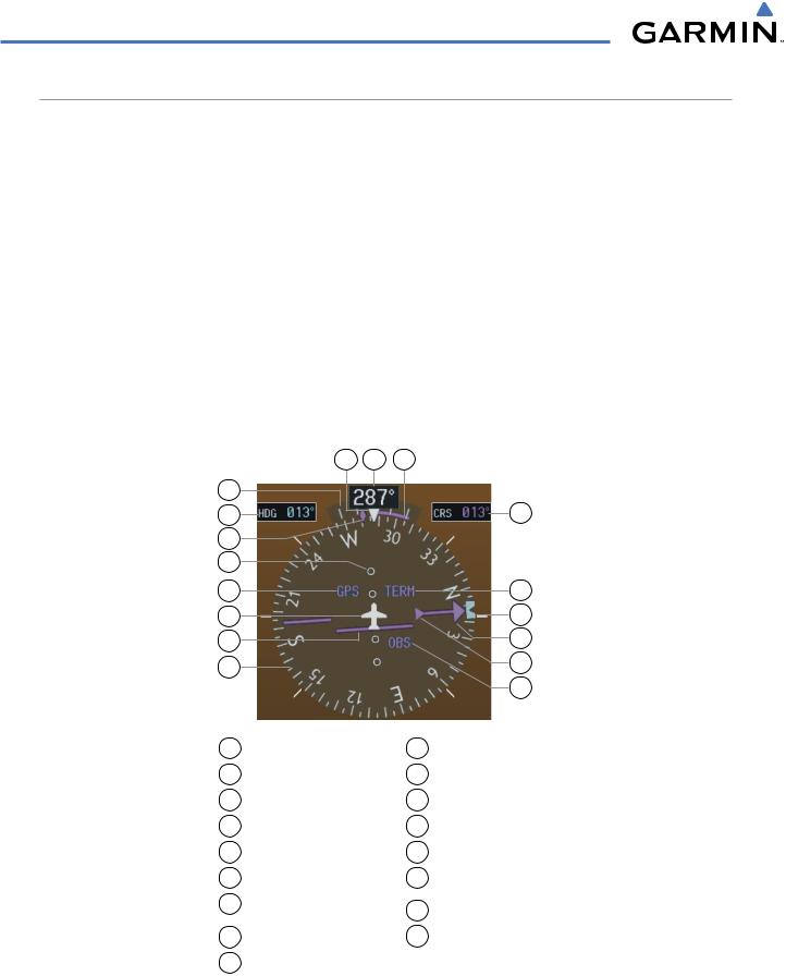
The Horizontal Situation Indicator (HSI) displays a rotating compass card in a heading-up orientation. Letters indicate the cardinal points and numeric labels occur every 30˚. Major tick marks are at 10˚ intervals and minor tick marks at 5˚ intervals. A digital reading of the current heading appears on top of the HSI, and the current track is represented on the HSI by a magenta diamond bug. The HSI also presents turn rate, course deviation, bearing, and navigation source information and is available in two formats (360˚ compass rose and 140˚ arc).
Changing the HSI display format:
1)Press the PFD Softkey
2)Press the HSI FRMT Softkey.
3)Press the 360 HSI or ARC HSI Softkey.
The 360˚ HSI (Figure 2-14) contains a Course Deviation Indicator (CDI), with a Course Pointer, To/From Indicator, and a sliding deviation bar and scale. The course pointer is a single line arrow (GPS, VOR1, and LOC1) or a double line arrow (VOR2 and LOC2) which points in the direction of the set course. The To/From arrow rotates with the course pointer and is displayed when the active NAVAID is received.
17 |
16 |
15 |
1 |
|
|
2 |
|
14 |
3 |
|
|
4 |
|
|
5 |
|
13 |
6 |
|
12 |
7 |
|
11 |
8 |
|
10 |
|
|
|
|
|
9 |
1 |
Turn Rate Indicator |
10 |
To/From Indicator |
2 |
Selected Heading |
11 |
Course Pointer |
3 |
Current Track Bug |
12 |
Heading Bug |
4 |
Lateral Deviation Scale |
13 |
Flight Phase |
5 |
Navigation Source |
14 |
Selected Course |
6 |
Aircraft Symbol |
15 |
Turn Rate/Heading |
7 |
Course Deviation Indicator |
|
Trend Vector |
16 |
Current Heading |
||
|
(CDI) |
|
|
8 |
Rotating Compass Rose |
17 |
Lubber Line |
9OBS Mode Active
Figure 2-14 Horizontal Situation Indicator (HSI)
2-10 |
Garmin G1000 Pilot’s Guide for Cessna Nav III |
190-00498-03 Rev.A |
FLIGHT INSTRUMENTS
The Arc HSI (Figure 2-15) is a 140˚ expanded section of the compass rose. The Arc HSI contains a Course Pointer, To/From Indicator, a sliding deviation indicator (the To/From and deviation indicators are combined), and a deviation scale. Upon station passage, the To/From Indicator flips and points to the tail of the aircraft, just like a conventional To/From flag. Depending on the navigation source, the CDI on the Arc HSI can appear in two different ways: an arrowhead (GPS, VOR, OBS) or a diamond (LOC).
|
Course Pointer |
Flight Phase Annunciation |
||
Navigation |
Course |
|||
Deviation |
||||
Source |
||||
and To/From |
||||
|
|
|
||
Lateral |
Indicator |
|||
|
||||
Deviation |
|
|||
Scale |
|
|
Figure 2-15 Arc HSI |
|
|
|
|
||
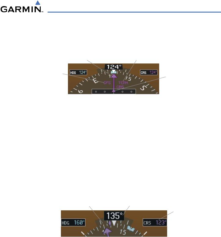
The Selected Heading is shown to the upper left of the HSI and is displayed in light blue. The light blue heading bug on the compass rose corresponds to the Selected Heading.
Adjusting the Selected Heading:
Turn the HDG Knob to set the Selected Heading.
Press the HDG Knob to synchronize the bug to the current heading.
The Selected Course is shown to the upper right of the HSI. The color of the Selected Course corresponds to the selected navigation source: magenta for GPS or green for NAV (VOR, LOC).
Adjusting the Selected Course:
Turn the CRS Knob to set the Selected Course.
Press the CRS Knob to re-center the CDI and return the course pointer to the bearing of the active waypoint or navigation station (see OBS Mode for adjusting a GPS course).
|
|
Current Track Bug |
Current Heading |
|||
|
|
|
|
|
|
Selected |
|
|
|
|
|
|
Course |
Selected |
|
|
|
|||
Heading |
|
|
|
|
|
Selected |
|
|
|
|
|
|
Heading |
|
|
|
|
|
|
|
|
|
|
|
|
|
Bug |
Figure 2-16 Heading and Course Indications
190-00498-03 Rev.A |
Garmin G1000 Pilot’s Guide for Cessna Nav III |
2-11 |
FLIGHT INSTRUMENTS
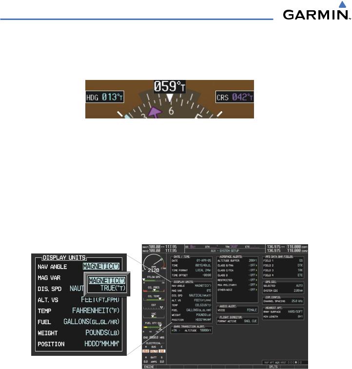
Navigation angles (track, heading, course, bearing) are corrected to the computed magnetic variation (‘Mag Var”) or referenced to true north (denoted ‘T’), set on the AUX - System Setup Page. When an approach referenced to true north has been loaded into the flight plan, the system generates a message to change the navigation angle setting to ‘True’ at the appropriate time.
Figure 2-17 Heading and Course Indications (True)
Changing the navigation angle setting:
1)Use the FMS Knob to select the AUX - System Setup Page on the MFD.
2)Press the FMS Knob to activate the cursor.
3)Turn the large FMS Knob to highlight ‘Nav Angle’ in the ‘Display Units’ box (Figure 2-18).
4)Turn the small FMS Knob to highlight the desired setting and press the ENT Key.
•TRUE - References angles to true north (denoted with ‘T’)
•MAGNETIC - Angles corrected to the computed magnetic variation (‘Mag Var’)
Figure 2-18 System Setup Page,
Navigation Angle Settings
2-12 |
Garmin G1000 Pilot’s Guide for Cessna Nav III |
190-00498-03 Rev.A |
FLIGHT INSTRUMENTS
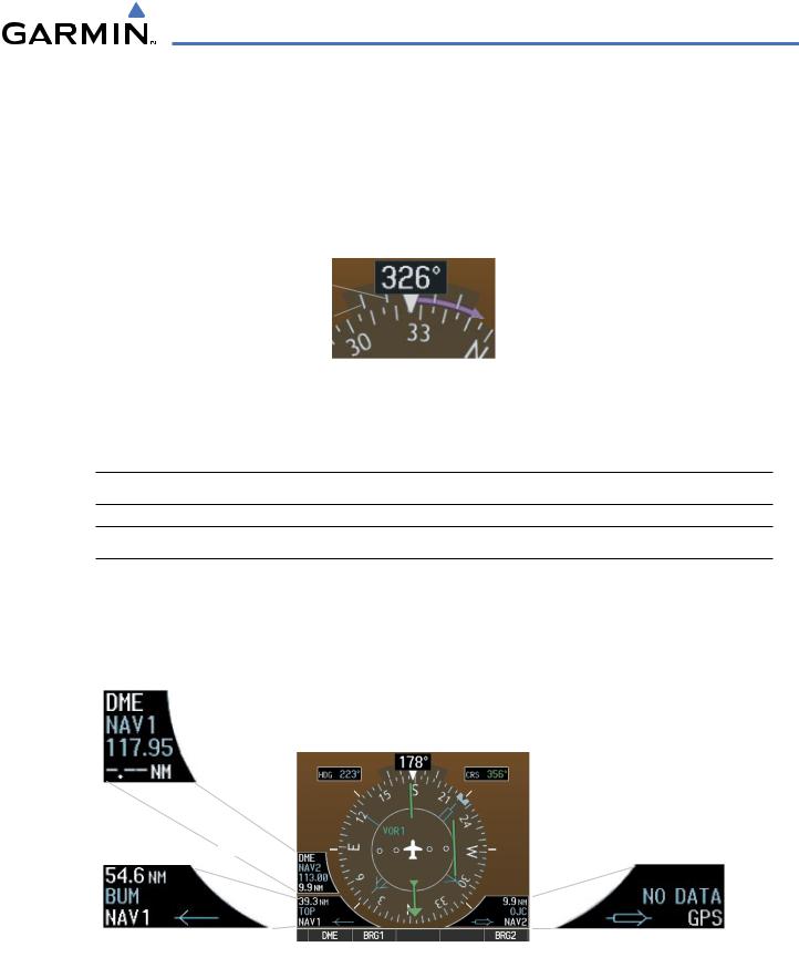
TURN RATE INDICATOR
The Turn Rate Indicator is located directly above the rotating compass card. Tick marks to the left and right of the lubber line denote half-standard and standard turn rates. A magenta Turn Rate Trend Vector shows the current turn rate. The end of the trend vector gives the heading predicted in 6 seconds, based on the present turn rate. A standard-rate turn is shown on the indicator by the trend vector stopping at the standard turn rate tick mark, corresponding to a predicted heading of 18˚ from the current heading. At rates greater than 4 deg/sec, an arrowhead appears at the end of the magenta trend vector and the prediction is no longer valid.
Half-Standard |
|
|
|
|
Turn Rate |
|
|
Arrow Shown |
|
|
|
|||
Standard |
|
|
||
|
|
for Turn Rate |
||
Turn Rate |
|
|
||
|
|
> 4 deg/sec |
||
|
|
|
|
|
Figure 2-19 Turn Rate Indicator and Trend Vector
BEARING POINTERS AND INFORMATION WINDOWS
 NOTE: ADF radio installation is optional.
 NOTE: When the Arc HSI is displayed, the Bearing Information windows and pointers are disabled.
Two bearing pointers and associated information can be displayed on the HSI for NAV, GPS, and ADF sources. The pointers are light blue and are single- (BRG1) or double-lined (BRG2); an icon is shown in the respective information window to indicate the pointer type. The bearing pointers never override the CDI and are visually separated from the CDI by a white ring (shown when bearing pointers are selected but not necessarily visible due to data unavailability).
|
|
|
|
|
|
|
Tuning Mode |
Bearing 1 |
Bearing 2 |
||||
|
|
|
|
|
|
|
|||||||
|
|
|
|
|
|
Frequency |
Pointer |
Pointer |
|||||
|
|
|
|
|
|
|
|
|
|
|
|||
|
|
|
|
|
|
|
|
|
|
|
|||
|
|
|
|
|
|
Distance |
|
|
|
|
|
||
|
|
|
|
|
|
|
|
|
|
|
|||
DME Information Window |
|
|
|
|
|
||||||||
|
|
|
|
|
|
|
|
|
|
|
|
No |
|
|
|
|
|
|
|
|
|
|
|
|
|
||
Distance to |
|
Station |
|
|
|
Waypoint |
|||||||
Bearing Source |
|
Identifier |
|
|
|
Selected |
|||||||
|
|
|
|
|
|
|
|
|
|
|
|
|
|
|
|
|
|
|
|
|
|
|
|
|
|
|
|
|
|
|
|
|
|
|
|
|
|
|
|
|
|
|
|
|
|
|
|
|
|
|
|
|
|
|
|
|
|
Bearing |
Pointer |
Pointer |
Bearing |
||||
Source |
Icon |
Icon |
Source |
||||
Bearing 1 Information Window |
Bearing 2 Information Window |
||||||
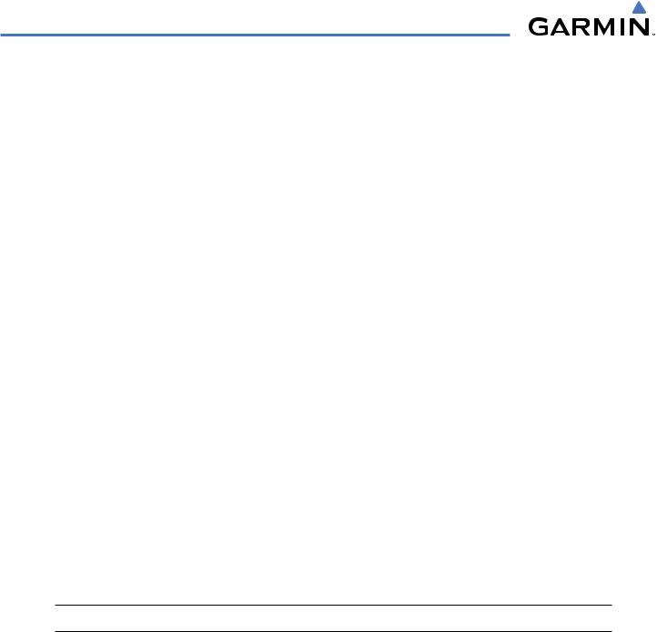
Figure 2-20 HSI with Bearing and DME Information
190-00498-03 Rev.A |
Garmin G1000 Pilot’s Guide for Cessna Nav III |
2-13 |
FLIGHT INSTRUMENTS
When a bearing pointer is displayed, its associated information window is also displayed. The Bearing Information windows (Figure 2-20) are displayed to the lower sides of the HSI and show:
•Bearing source (NAV, GPS, ADF)
•Pointer icon (BRG1 = single line, BRG2 = double line)
•Frequency (NAV, ADF)
•Station/waypoint identifier (NAV, GPS)
•GPS-derived great circle distance to bearing source
If the NAV radio is the bearing source and is tuned to an ILS frequency (refer to the Audio Panel and CNS Section for information on tuning the radios), the bearing pointer is removed from the HSI and the frequency is replaced with “ILS”. When NAV1 or NAV2 is the selected bearing source, the frequency is replaced by the station identifier when the station is within range. If GPS is the bearing source, the active waypoint identifier is displayed in lieu of a frequency.
The bearing pointer is removed from the HSI and “NO DATA” is displayed in the information window if:
•The NAV radio is not receiving the tuned VOR station
•GPS is the bearing source and an active waypoint is not selected
Selecting bearing display and changing sources:
1)Press the PFD Softkey.
2)Press a BRG Softkey to display the desired bearing pointer and information window with a NAV source.
3)Press the BRG Softkey again to change the bearing source to GPS.
4)Press the BRG Softkey a third time to change the bearing source to ADF (note: ADF radio installation is optional).
5)To remove the bearing pointer and information window, press the BRG Softkey again.
DME INFORMATION
 NOTE: DME radio installation is optional.
The DME Information Window is displayed above the BRG1 Information Window and shows the DME label, tuning mode (NAV1, NAV2, or HOLD), frequency, and distance. When a signal is invalid, the distance is replaced by “–.– – NM”. Refer to the Audio Panel and CNS Section for information on tuning the radios.
Displaying the DME Information Window:
1)Press the PFD Softkey.
2)Press the DME Softkey to display the DME Information Window above the BRG1 Information Window.
3)To remove the DME Information Window, press the DME Softkey again.
2-14 |
Garmin G1000 Pilot’s Guide for Cessna Nav III |
190-00498-03 Rev.A |