

FLIGHT MANAGEMENT
AIRWAYS
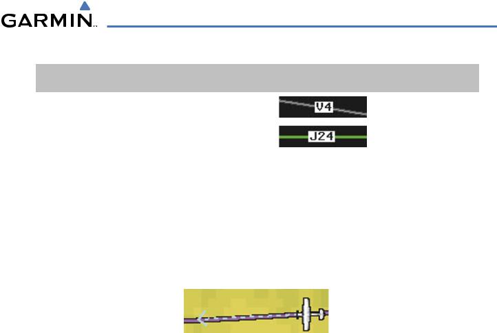
This airways discussion is based upon the North American airway structure. The airway structure in places other than North America vary by location, etc. and are not discussed in this book. Low Altitude Airways (or Victor Airways) primarily serve smaller piston-engine, propeller-driven airplanes on shorter routes and at lower altitudes. Airways are eight nautical miles wide and start 1,200 feet above ground level (AGL) and extend up to 18,000 feet mean sea level (MSL). Low Altitude Airways are designated with a “V” before the airway number (hence the name “Victor Airways”) since they run primarily between VORs.
High Altitude Airways (or Jet Routes) primarily serve airliners, jets, turboprops, and turbocharged piston aircraft operating above 18,000 feet MSL. Jet Routes start at 18,000 feet MSL and extend upward to 45,000 feet MSL (altitudes above 18,000 feet are called “flight levels” and are described as FL450 for 45,000 feet MSL). Jet Routes are designated with a “J” before the route number.
Low Altitude Airways are drawn in gray (the same shade used for roads). High Altitude Airways are drawn in green. When both types of airways are displayed, high altitude airways are drawn on top of Low Altitude Airways.
When airways are selected for display on the map, the airway waypoints (VORs, NDBs and Intersections) are also displayed.
Low Altitude
Airway
(Victor Airway)
High Altitude
Airway
(Jet Route)
Figure 5-22 Airways on MFD Navigation Page
190-00498-03 Rev.A |
Garmin G1000 Pilot’s Guide for Cessna Nav III |
5-23 |
FLIGHT MANAGEMENT
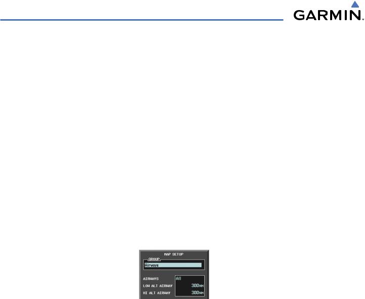
Airways may be displayed on the map at the pilot’s discretion using either a combination of AIRWAY Softkey presses, or menu selections using the MENU Key from the Navigation Map Page. The Airway range can also be programmed to only display Airways on the MFD when the map range is at or below a specific number.
Displaying/removing airways:
1)Press the MAP Softkey.
2)Press the AIRWAYS Softkey. Both High and Low Altitude Airways are displayed.
3)Press the AIRWY ON Softkey to display the Low Altitude Airways only.
4)Press the AIRWY LO Softkey to display the High Altitude Airways only.
5)Press the AIRWY HI Softkey to remove the High Altitude Airways. No airways are displayed.
Or:
1)Press the MENU Key with the Navigation Map Page displayed. The cursor flashes on the ‘Map Setup’ option.
2)Press the ENT Key. The Map Setup Menu is displayed.
3)Turn the small FMS Knob to select the ‘Airways’ group, and press the ENT Key.
4)Turn the large FMS Knob to highlight the ‘AIRWAYS’ field.
5)Turn the FMS Knob to select ‘Off’,‘All’,‘LO Only’, or ‘HI Only’, and press the ENT Key.
6)Press the FMS Knob to return to the Navigation Map Page.
Airway Display Selection |
|
|
|
Low Altitude Airway Range |
|
|
|||
Off, All, LO ALT Only, HI ALT Only |
|
|||
|
||||
|
|
|||
|
|
|
|
High Altitude Airway Range |
|
|
|
|
|
Figure 5-23 Navigation Map Setup Menu - AIRWAYS Setup |
||||
The airway range is the maximum map range on which airways are displayed.
Selecting an airway range (LOW ALT AIRWAY or HI ALT AIRWAY):
1)Press the MENU Key with the Navigation Map Page displayed. The cursor flashes on the ‘Map Setup’ option.
2)Press the ENT Key. The Map Setup Menu is displayed.
3)Select the ‘Airway’ group.
4)Press the ENT Key.
5)Highlight the ‘LOW ALT AIRWAY’ or ‘HI ALT AIRWAY’ range field.
6)To change the range setting, turn the small FMS Knob to display the range list.
7)Select the desired range using the small FMS Knob.
8)Press the ENT Key.
9)Press the FMS Knob to return to the Navigation Map Page.
5-24 |
Garmin G1000 Pilot’s Guide for Cessna Nav III |
190-00498-03 Rev.A |
FLIGHT MANAGEMENT
The following range items are configurable on the airways menu:
Airway Type |
|
Symbol |
Default |
Maximum |
|
|
|
|
|
Range (nm) |
Range (nm) |
Low Altitude Airway (LOW ALT AIRWAY) |
|
|
200 |
500 |
|
|
|
|
|
|
|
High Altitude Airway (HI ALT AIRWAY) |
|
|
300 |
500 |
|
|
|
|
|
|
|
|
|
Table 5-4 Airway Range Information |
|
|
|
|
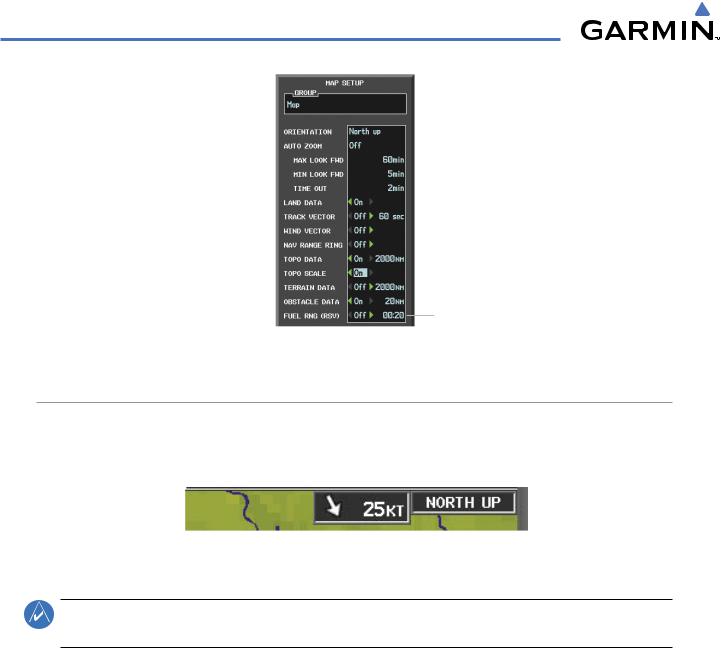
TRACK VECTOR |
|
|
|
|
The Navigation Map can display a track vector that is useful in minimizing track angle error. The track vector is a dashed light blue line segment with an arrowhead attached to the end, extended to a predicted location along the current aircraft track. The track vector look-ahead time is selectable (30 sec, 60 sec (default), 2 min, 5 min, 10 min, 20 min) and determines the length of the track vector. The arrowhead is continuously pointing to the predicted aircraft location.
 Track Vector
Figure 5-24 Navigation Map -Track Vector
Displaying/removing the track vector:
1)Press the MENU Key with the Navigation Map Page displayed. The cursor flashes on the ‘Map Setup’ option.
2)Press the ENT Key. The Map Setup Menu is displayed.
3)Select the ‘Map’ group.
4)Press the ENT Key.
5)Highlight the ‘TRACK VECTOR’ field.
6)Select ‘On’ or ‘Off’. Press the ENT Key to accept the selected option. The flashing cursor highlights the look ahead time field. Use the FMS Knob to select the desired time. Press the ENT Key.
7)Press the FMS Knob to return to the Navigation Map Page.
190-00498-03 Rev.A |
Garmin G1000 Pilot’s Guide for Cessna Nav III |
5-25 |
FLIGHT MANAGEMENT
Wind Vector On/Off |
|
|
|
Track Vector |
|
|
|
||
|
|
|
- On/Off |
|
|
|
|||
|
|
|
|
- Look Ahead Time |
Nav Range Ring On/Off |
|
|||
|
|
|||
Fuel Range
- On/Off
- Fuel Reserve Time
Figure 5-25 Navigation Map Setup Menu -TRACK VECTOR,WIND VECTOR, NAV RANGE RING, FUEL RANGE RING Setup
WIND VECTOR
The map displays a wind vector arrow in the upper right-hand portion of the screen. Wind vector information is displayed as a white arrow pointing in the direction in which the wind is moving for wind speeds greater than or equal to 1 kt.
Wind Direction |
|
|
|
Wind Speed |
|
|
|
Figure 5-26 Navigation Map - Wind Vector
NOTE: The wind vector is not displayed until the aircraft is moving. It is not displayed on the Waypoint Information pages.
Displaying/removing the wind vector:
1)Press the MENU Key with the Navigation Map Page displayed. The cursor flashes on the ‘Map Setup’ option.
2)Press the ENT Key. The Map Setup Menu is displayed.
3)Select the ‘Map’ group.
4)Press the ENT Key.
5)Highlight the ‘WIND VECTOR’ field.
6)Select ‘On’ or ‘Off’.
7)Press the FMS Knob to return to the Navigation Map Page.
5-26 |
Garmin G1000 Pilot’s Guide for Cessna Nav III |
190-00498-03 Rev.A |