

- •Section 1 System Overview
- •1.1 System Description
- •1.2 Line Replaceable Units (LRU)
- •1.3 G1000 Controls
- •PFD/MFD Controls
- •Audio Panel Controls
- •1.4 Secure Digital (SD) Cards
- •1.5 System Power-up
- •1.6 System Operation
- •Normal Display Operation
- •Reversionary Display Operation
- •AHRS Operation
- •G1000 System Annunciations
- •Softkey Function
- •GPS Receiver Operation
- •1.7 Accessing G1000 Functionality
- •Menus
- •MFD Page Groups
- •MFD System Pages
- •1.8 Display Backlighting
- •Automatic Adjustment
- •Manual Adjustment
- •Section 2 Flight Instruments
- •2.1 Flight Instruments
- •Airspeed Indicator
- •Attitude Indicator
- •Altimeter
- •Vertical Speed Indicator (VSI)
- •Vertical Deviation
- •Horizontal Situation Indicator (HSI)
- •Course Deviation Indicator (CDI)
- •2.2 Supplemental Flight Data
- •Outside Air Temperature
- •Wind Data
- •Vertical Navigation (VNV) Indications
- •2.3 PFD Annunciations and Alerting Functions
- •G1000 System Alerting
- •Marker Beacon Annunciations
- •Traffic Annunciation
- •TAWS Annunciations
- •Altitude Alerting
- •Low Altitude Annunciation
- •Minimum Descent Altitude/Decision Height Alerting
- •2.4 Abnormal Operations
- •Abnormal GPS Conditions
- •Unusual Attitudes
- •Section 3 Engine Indication System (EIS)
- •3.1 Engine Display
- •3.2 Lean Display
- •Normally-aspirated Aircraft
- •Turbocharged Aircraft
- •3.3 System Display
- •Section 4 audio panel and CNS
- •4.1 Overview
- •MFD/PFD Controls and Frequency Display
- •Audio Panel Controls
- •4.2 COM Operation
- •COM Transceiver Selection and Activation
- •COM Transceiver Manual Tuning
- •Quick-Tuning and Activating 121.500 MHz
- •Auto-tuning the COM Frequency
- •Frequency Spacing
- •Automatic Squelch
- •Volume
- •4.3 NAV Operation
- •NAV Radio Selection and Activation
- •NAV Receiver Manual Tuning
- •Auto-tuning a NAV Frequency from the MFD
- •Marker Beacon Receiver
- •DME Tuning (Optional)
- •4.4 GTX 33 Mode S Transponder
- •Transponder Controls
- •Transponder Mode Selection
- •Entering a Transponder Code
- •IDENT Function
- •Flight ID Reporting
- •4.5 Additional Audio Panel Functions
- •Power-Up
- •Mono/Stereo Headsets
- •Speaker
- •Intercom
- •Passenger Address (PA) System
- •Clearance Recorder and Player
- •Entertainment Inputs
- •4.6 Audio Panel Preflight Procedure
- •4.7 Abnormal Operation
- •Stuck Microphone
- •COM Tuning Failure
- •Audio Panel Fail-Safe Operation
- •Reversionary Mode
- •Section 5 Flight Management
- •5.1 Introduction
- •Navigation Status Box
- •5.2 Using Map Displays
- •Map Orientation
- •Map Range
- •Map Panning
- •Measuring Bearing and Distance
- •Topography
- •Map Symbols
- •Airways
- •Track Vector
- •Wind Vector
- •Nav Range Ring
- •Fuel Range Ring
- •5.3 Waypoints
- •Airports
- •Intersections
- •NDBs
- •VORs
- •User Waypoints
- •5.4 Airspaces
- •5.5 Direct-to-Navigation
- •5.6 Flight Planning
- •Flight Plan Creation
- •Adding Waypoints To An Existing Flight Plan
- •Adding Airways to a Flight Plan
- •Adding Procedures To A Stored Flight Plan
- •Flight Plan Storage
- •Flight Plan Editing
- •Along Track Offsets
- •Parallel Track
- •Activating a Flight Plan Leg
- •Inverting a Flight Plan
- •Flight Plan Views
- •Closest Point of FPL
- •5.7 Vertical Navigation
- •Altitude Constraints
- •5.8 Procedures
- •Departures
- •Arrivals
- •Approaches
- •5.9 Trip Planning
- •Trip Planning
- •5.10 RAIM Prediction
- •5.11 Navigating a Flight Plan
- •5.12 Abnormal Operation
- •Section 6 Hazard Avoidance
- •6.1 XM Satellite Weather
- •Activating Services
- •Using XM Satellite Weather Products
- •6.2 WX-500 Stormscope (Optional)
- •Setting Up Stormscope on the Navigation Map
- •Selecting the Stormscope Page
- •6.3 Terrain Proximity
- •Displaying Terrain Proximity Data
- •Terrain Proximity Page
- •6.4 TAWs (Optional)
- •Displaying TAWS Data
- •TAWS Page
- •TAWS Alerts
- •System Status
- •6.5 Traffic Information Service (TIS)
- •Displaying TRAFFIC Data
- •Traffic Map Page
- •TIS Alerts
- •System Status
- •6.6 Traffic Advisory System (TAS) (Optional)
- •TAS Symbology
- •Operation
- •Altitude Display
- •Traffic Map Page Display Range
- •TAS Alerts
- •System Status
- •6.7 ADS-B Traffic (Optional)
- •Section 7 Automatic Flight Control System
- •7.2 Flight Director Operation
- •Activating the Flight Director
- •AFCS Status Box
- •Command Bars
- •Flight Director Modes
- •7.3 Vertical Modes
- •Pitch Hold Mode (PIT)
- •Selected Altitude capture Mode (ALTs)
- •Altitude hold mode (alt)
- •Vertical Speed Mode (VS)
- •Flight Level Change Mode (FLC)
- •Vertical Navigation Modes (VPTH, ALTV)
- •Glidepath Mode (GP) (waas only)
- •Glideslope Mode (GS)
- •Go Around (GA) Mode
- •7.4 Lateral Modes
- •Roll Hold Mode (ROL)
- •Heading Select Mode (HDG)
- •Navigation mode (GPS, VOR, LOC)
- •Approach mode (GPS, VAPP, LOC)
- •Backcourse Mode (BC)
- •7.5 Autopilot Operation
- •Engaging the Autopilot
- •Control Wheel Steering
- •Disengaging the Autopilot
- •7.6 Example Procedures
- •Departure
- •Intercepting a VOR Radial
- •Flying a Flight Plan/GPS Course
- •Descent
- •Approach
- •Go Around/Missed Approach
- •7.7 AFCS Annunciations and Alerts
- •AFCS Status Alerts
- •Overspeed Protection
- •Section 8 Additional Features
- •8.1 SafeTaxi
- •SafeTaxi Cycle Number and Revision
- •8.2 ChartView
- •ChartView Softkeys
- •Terminal Procedures Charts
- •Chart Options
- •Day/Night View
- •ChartView Cycle Number and Expiration Date
- •8.3 FliteCharts
- •FliteCharts Softkeys
- •Terminal Procedures Charts
- •Chart Options
- •Day/Night View
- •FliteCharts Cycle Number and Expiration Date
- •8.4 XM Radio Entertainment (Optional)
- •Activating XM Satellite Radio Services
- •Using XM Radio
- •Automatic Audio Muting
- •8.5 Scheduler
- •8.5 Abnormal Operation
- •Annunciations and Alerts
- •Alert Level Definitions
- •Nav III Aircraft Alerts
- •CO Guardian Messages
- •G1000 System Annunciations
- •Other G1000 Aural Alerts
- •G1000 System Message Advisories
- •AFCS Alerts
- •TAWS ALERTS
- •TAWS System Status Annunciations
- •SD Card Use
- •Jeppesen Databases
- •Garmin Databases
- •Glossary
- •Frequently Asked Questions
- •General TIS Information
- •Introduction
- •TIS vs. TAS/TCAS
- •TIS Limitations
- •Map Symbols
- •Index
FLIGHT MANAGEMENT
RESTRICTIONS ON ADDING AIRWAYS
Someairwayshavedirectionalrestrictionsonallorpartoftheroute. Airway“A2”inEuropehasadirectional restriction over the whole route such that it can be flown only in the direction MTD-ABB-BNE-DEVAL.
Airway “UR975” in North Africa has more complicated directional restrictions within the list of airway waypoints AMANO, VAKOR, LIBRO NELDA, DIRKA, GZO, KOSET, and SARKI:
•Starting from AMANO, the airway can be flown only to LIBRO.
•Starting from SARKI, the airway can be flown only to LIBRO.
•Between NELDA and GZO, the airway can be flown in either direction.
In the US, airways that are “one-way” for specified hours of operation are not uncommon. These airways are always bidirectional in the G1000 database.
The system only allows correct airway sequences to be inserted. If the pilot subsequently inverts the flight plan, the system inverts the airway waypoint sequence and removes the airway header.
ADDING PROCEDURES TO A STORED FLIGHT PLAN
The G1000 allows the pilot to insert pre-defined instrument procedures from the navigation database into a flight plan. The procedures are designed to facilitate routing of traffic leaving an airport (departure), arriving at an airport (arrival), and landing at an airport (approach). See the procedures section for more details.
Flight Plan Name
Flight Plan
Waypoint List
Softkeys
LoadDeparture-
Load Arrival -
Load Approach -
Activate Flight Plan
Figure 5-62 Stored Flight Plan Page
190-00498-03 Rev.A |
Garmin G1000 Pilot’s Guide for Cessna Nav III |
5-63 |
FLIGHT MANAGEMENT
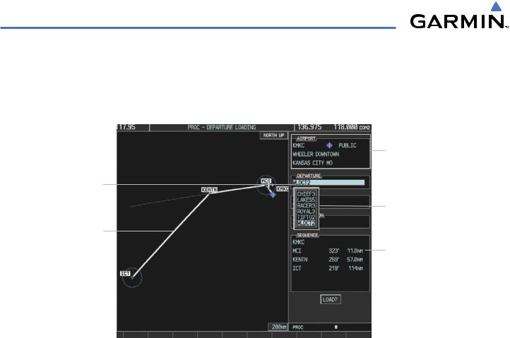
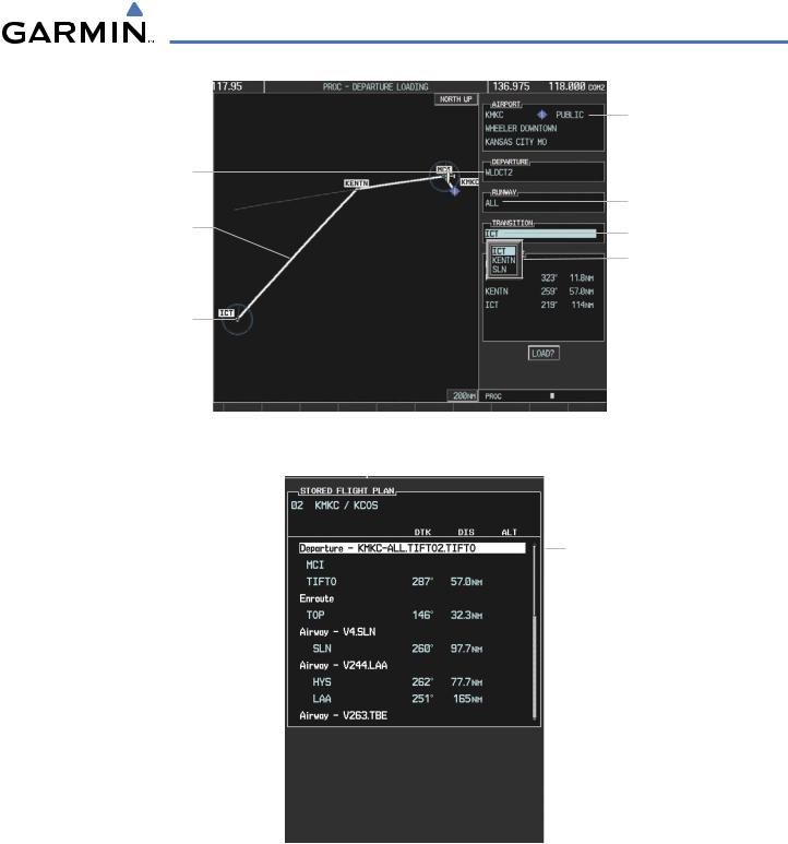
DEPARTURE (DP)
A Departure Procedure (DP) is loaded at the departure airport in the flight plan. Only one departure can be loaded at a time in a flight plan. The route is defined by selection of a departure, the transition waypoints, and a runway.
Departure Airport
Selected
Departure
Departures Available at
KMKC
Preview of
Selected
Departure Departure Waypoint
Sequence
Figure 5-63 Departure Loading Page - Selecting the Departure
Loading a departure procedure into a stored flight plan:
1)Select a stored flight plan from the Flight Plan Catalog Page.
2)Press the EDIT Softkey; or press the MENU Key, select ‘EDIT FLIGHT PLAN’, and press the ENT Key. The Stored Flight Plan Page is displayed.
3)Press the LD DP Softkey; or press the MENU Key, select “Load Departure”, and press the ENT Key. The Departure Loading Page is displayed.
4)Select a departure. Press the ENT Key.
5)Select a transition for the selected departure. Press the ENT Key.
6)Select a runway served by the selected departure, if required. Press the ENT Key.
7)Press the ENT Key to load the selected departure procedure.
5-64 |
Garmin G1000 Pilot’s Guide for Cessna Nav III |
190-00498-03 Rev.A |
FLIGHT MANAGEMENT
Selected
Departure
Preview of
Selected
Departure
Selected
Departure End
Point
Departure Airport
Selected Runway
Selected Transition
Departure Transition
Points Available
Figure 5-64 Departure Loading Page - Selecting Transition
Inserted Departure Header
- Departure Identifier: [departure airport]-[departure runway]. [departure transition]. [departure end point]
(e.g., KMKC-ALL.TIFTO2.TIFTO)
Figure 5-65 Stored Flight Plan Page - Departure Inserted
190-00498-03 Rev.A |
Garmin G1000 Pilot’s Guide for Cessna Nav III |
5-65 |
FLIGHT MANAGEMENT
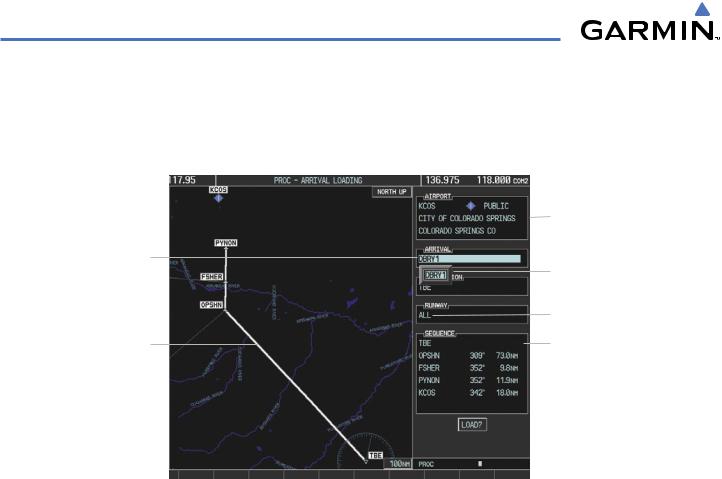
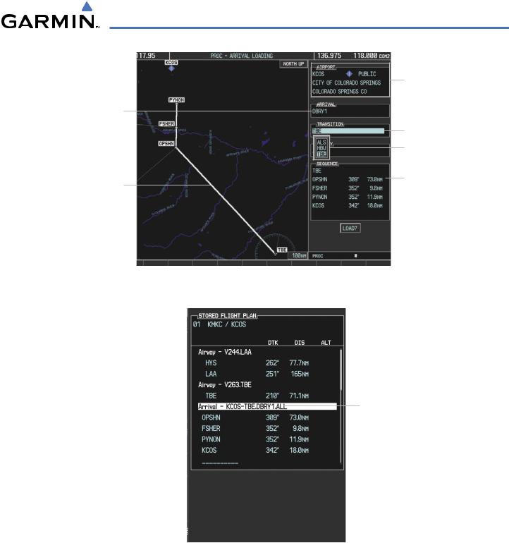
ARRIVAL (STAR)
A Standard Terminal Arrival (STAR) is loaded at the destination airport in the flight plan. Only one arrival can be loaded at a time in a flight plan. The route is defined by selection of an arrival, the transition waypoints, and a runway.
|
|
|
|
Destination Airport |
|
|
|
|
|
Selected Arrival |
|
|
Arrivals Available at |
|
|
|
|
|
|
|
|
|
|
KCOS |
|
|
|
||
|
|
|
|
Selected Runway |
Preview of |
|
|
Arrival Waypoint |
|
Selected Arrival |
|
|
Sequence |
|
Figure 5-66 Arrival Loading Page - Selecting the Arrival
Loading an arrival procedure into a stored flight plan:
1)Select a stored flight plan from the Flight Plan Catalog Page.
2)Press the EDIT Softkey; or press the MENU Key, select ‘EDIT FLIGHT PLAN’, and press the ENT Key. The Stored Flight Plan Page is displayed.
3)Press the LD STAR Softkey; or press the MENU Key, select “Load Arrival”, and press the ENT Key. The Arrival Loading Page is displayed.
4)Select an arrival. Press the ENT Key.
5)Select a transition for the selected arrival. Press the ENT Key.
6)Select a runway served by the selected arrival, if required. Press the ENT Key.
7)Press the ENT Key to load the selected arrival procedure.
5-66 |
Garmin G1000 Pilot’s Guide for Cessna Nav III |
190-00498-03 Rev.A |
FLIGHT MANAGEMENT
Destination Airport
Selected Arrival
Selected Transition
Transitions Available with DBRY1
Arrival Waypoint
Preview of Sequence
Selected Arrival
Figure 5-67 Arrival Loading Page - Selecting the Transition
Inserted Arrival Header
- Arrival Identifier:
[arrival airport]-[arrival transition].
[arrival].[arrival runway]
(e.g., KCOS-ALS.DBRY1.ALL)
Figure 5-68 Stored Flight Plan Page - Arrival Inserted
190-00498-03 Rev.A |
Garmin G1000 Pilot’s Guide for Cessna Nav III |
5-67 |
FLIGHT MANAGEMENT
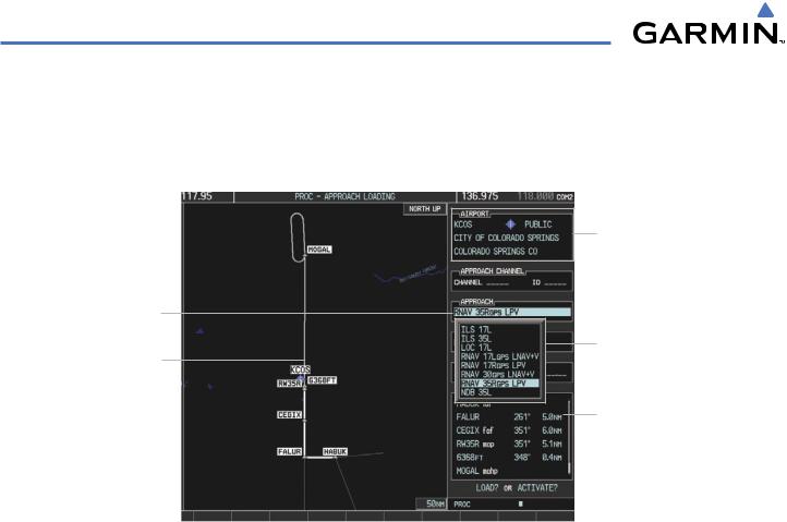
APPROACH (APPR)
An Approach Procedure (APPR) can be loaded at any airport that has an approach available. Only one approach can be loaded at a time in a flight plan. The route for a selected approach is defined by designating transition waypoints.
Destination Airport
Selected
Approach
Approaches Available
Preview of at KCOS
Selected
Approach
Approach Waypoint
Sequence
Figure 5-69 Approach Loading Page - Selecting the Approach
Loading an approach procedure into a stored flight plan:
1)Select a stored flight plan from the Flight Plan Catalog Page.
2)Press the EDIT Softkey; or press the MENU Key, select ‘EDIT FLIGHT PLAN’, and press the ENT Key. The Stored Flight Plan Page is displayed.
3)Press the LD APR Softkey; or press the MENU Key, select “Load Approach”, and press the ENT Key. The Approach Loading Page is displayed.
4)Select an approach. Press the ENT Key.
5)Select a transition for the selected arrival. Press the ENT Key.
6)Press the ENT Key to load the selected approval procedure.
5-68 |
Garmin G1000 Pilot’s Guide for Cessna Nav III |
190-00498-03 Rev.A |