

- •Section 1 System Overview
- •1.1 System Description
- •1.2 Line Replaceable Units (LRU)
- •1.3 G1000 Controls
- •PFD/MFD Controls
- •Audio Panel Controls
- •1.4 Secure Digital (SD) Cards
- •1.5 System Power-up
- •1.6 System Operation
- •Normal Display Operation
- •Reversionary Display Operation
- •AHRS Operation
- •G1000 System Annunciations
- •Softkey Function
- •GPS Receiver Operation
- •1.7 Accessing G1000 Functionality
- •Menus
- •MFD Page Groups
- •MFD System Pages
- •1.8 Display Backlighting
- •Automatic Adjustment
- •Manual Adjustment
- •Section 2 Flight Instruments
- •2.1 Flight Instruments
- •Airspeed Indicator
- •Attitude Indicator
- •Altimeter
- •Vertical Speed Indicator (VSI)
- •Vertical Deviation
- •Horizontal Situation Indicator (HSI)
- •Course Deviation Indicator (CDI)
- •2.2 Supplemental Flight Data
- •Outside Air Temperature
- •Wind Data
- •Vertical Navigation (VNV) Indications
- •2.3 PFD Annunciations and Alerting Functions
- •G1000 System Alerting
- •Marker Beacon Annunciations
- •Traffic Annunciation
- •TAWS Annunciations
- •Altitude Alerting
- •Low Altitude Annunciation
- •Minimum Descent Altitude/Decision Height Alerting
- •2.4 Abnormal Operations
- •Abnormal GPS Conditions
- •Unusual Attitudes
- •Section 3 Engine Indication System (EIS)
- •3.1 Engine Display
- •3.2 Lean Display
- •Normally-aspirated Aircraft
- •Turbocharged Aircraft
- •3.3 System Display
- •Section 4 audio panel and CNS
- •4.1 Overview
- •MFD/PFD Controls and Frequency Display
- •Audio Panel Controls
- •4.2 COM Operation
- •COM Transceiver Selection and Activation
- •COM Transceiver Manual Tuning
- •Quick-Tuning and Activating 121.500 MHz
- •Auto-tuning the COM Frequency
- •Frequency Spacing
- •Automatic Squelch
- •Volume
- •4.3 NAV Operation
- •NAV Radio Selection and Activation
- •NAV Receiver Manual Tuning
- •Auto-tuning a NAV Frequency from the MFD
- •Marker Beacon Receiver
- •DME Tuning (Optional)
- •4.4 GTX 33 Mode S Transponder
- •Transponder Controls
- •Transponder Mode Selection
- •Entering a Transponder Code
- •IDENT Function
- •Flight ID Reporting
- •4.5 Additional Audio Panel Functions
- •Power-Up
- •Mono/Stereo Headsets
- •Speaker
- •Intercom
- •Passenger Address (PA) System
- •Clearance Recorder and Player
- •Entertainment Inputs
- •4.6 Audio Panel Preflight Procedure
- •4.7 Abnormal Operation
- •Stuck Microphone
- •COM Tuning Failure
- •Audio Panel Fail-Safe Operation
- •Reversionary Mode
- •Section 5 Flight Management
- •5.1 Introduction
- •Navigation Status Box
- •5.2 Using Map Displays
- •Map Orientation
- •Map Range
- •Map Panning
- •Measuring Bearing and Distance
- •Topography
- •Map Symbols
- •Airways
- •Track Vector
- •Wind Vector
- •Nav Range Ring
- •Fuel Range Ring
- •5.3 Waypoints
- •Airports
- •Intersections
- •NDBs
- •VORs
- •User Waypoints
- •5.4 Airspaces
- •5.5 Direct-to-Navigation
- •5.6 Flight Planning
- •Flight Plan Creation
- •Adding Waypoints To An Existing Flight Plan
- •Adding Airways to a Flight Plan
- •Adding Procedures To A Stored Flight Plan
- •Flight Plan Storage
- •Flight Plan Editing
- •Along Track Offsets
- •Parallel Track
- •Activating a Flight Plan Leg
- •Inverting a Flight Plan
- •Flight Plan Views
- •Closest Point of FPL
- •5.7 Vertical Navigation
- •Altitude Constraints
- •5.8 Procedures
- •Departures
- •Arrivals
- •Approaches
- •5.9 Trip Planning
- •Trip Planning
- •5.10 RAIM Prediction
- •5.11 Navigating a Flight Plan
- •5.12 Abnormal Operation
- •Section 6 Hazard Avoidance
- •6.1 XM Satellite Weather
- •Activating Services
- •Using XM Satellite Weather Products
- •6.2 WX-500 Stormscope (Optional)
- •Setting Up Stormscope on the Navigation Map
- •Selecting the Stormscope Page
- •6.3 Terrain Proximity
- •Displaying Terrain Proximity Data
- •Terrain Proximity Page
- •6.4 TAWs (Optional)
- •Displaying TAWS Data
- •TAWS Page
- •TAWS Alerts
- •System Status
- •6.5 Traffic Information Service (TIS)
- •Displaying TRAFFIC Data
- •Traffic Map Page
- •TIS Alerts
- •System Status
- •6.6 Traffic Advisory System (TAS) (Optional)
- •TAS Symbology
- •Operation
- •Altitude Display
- •Traffic Map Page Display Range
- •TAS Alerts
- •System Status
- •6.7 ADS-B Traffic (Optional)
- •Section 7 Automatic Flight Control System
- •7.2 Flight Director Operation
- •Activating the Flight Director
- •AFCS Status Box
- •Command Bars
- •Flight Director Modes
- •7.3 Vertical Modes
- •Pitch Hold Mode (PIT)
- •Selected Altitude capture Mode (ALTs)
- •Altitude hold mode (alt)
- •Vertical Speed Mode (VS)
- •Flight Level Change Mode (FLC)
- •Vertical Navigation Modes (VPTH, ALTV)
- •Glidepath Mode (GP) (waas only)
- •Glideslope Mode (GS)
- •Go Around (GA) Mode
- •7.4 Lateral Modes
- •Roll Hold Mode (ROL)
- •Heading Select Mode (HDG)
- •Navigation mode (GPS, VOR, LOC)
- •Approach mode (GPS, VAPP, LOC)
- •Backcourse Mode (BC)
- •7.5 Autopilot Operation
- •Engaging the Autopilot
- •Control Wheel Steering
- •Disengaging the Autopilot
- •7.6 Example Procedures
- •Departure
- •Intercepting a VOR Radial
- •Flying a Flight Plan/GPS Course
- •Descent
- •Approach
- •Go Around/Missed Approach
- •7.7 AFCS Annunciations and Alerts
- •AFCS Status Alerts
- •Overspeed Protection
- •Section 8 Additional Features
- •8.1 SafeTaxi
- •SafeTaxi Cycle Number and Revision
- •8.2 ChartView
- •ChartView Softkeys
- •Terminal Procedures Charts
- •Chart Options
- •Day/Night View
- •ChartView Cycle Number and Expiration Date
- •8.3 FliteCharts
- •FliteCharts Softkeys
- •Terminal Procedures Charts
- •Chart Options
- •Day/Night View
- •FliteCharts Cycle Number and Expiration Date
- •8.4 XM Radio Entertainment (Optional)
- •Activating XM Satellite Radio Services
- •Using XM Radio
- •Automatic Audio Muting
- •8.5 Scheduler
- •8.5 Abnormal Operation
- •Annunciations and Alerts
- •Alert Level Definitions
- •Nav III Aircraft Alerts
- •CO Guardian Messages
- •G1000 System Annunciations
- •Other G1000 Aural Alerts
- •G1000 System Message Advisories
- •AFCS Alerts
- •TAWS ALERTS
- •TAWS System Status Annunciations
- •SD Card Use
- •Jeppesen Databases
- •Garmin Databases
- •Glossary
- •Frequently Asked Questions
- •General TIS Information
- •Introduction
- •TIS vs. TAS/TCAS
- •TIS Limitations
- •Map Symbols
- •Index
FLIGHT MANAGEMENT
5.10 RAIM PREDICTION
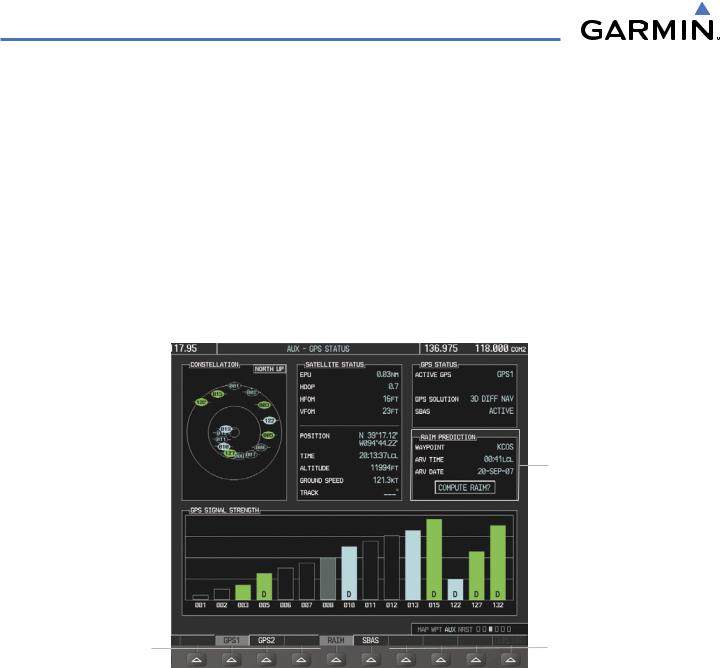
RAIM (Receiver Autonomous Integrity Monitoring) is a GPS receiver function that performs a consistency check on all tracked satellites. RAIM ensures that the available satellite geometry allows the receiver to calculate a position within a specified RAIM protection limit (4.0 nm for oceanic, 2.0 nm for enroute, 1.0 nm for terminal, and 0.3 nm for non-precision approaches). During oceanic, enroute, and terminal phases of flight, RAIM is available nearly 100% of the time. The RAIM prediction function also indicates whether RAIM is available at a specified date and time. RAIM computations predict satellite coverage within ±15 min of the specified arrival date and time. Because of the tighter protection limit on approaches, there may be times when RAIM is not available. RAIM prediction must be initiated manually if there is concern over WAAS coverage at the destination or some other reason that compromises navigation precision. If RAIM is not predicted to be available for the final approach course, the approach does not become active. If RAIM is not available when crossing the FAF, the missed approach procedure must be flown.
RAIM PREDICTION Box
- Prediction Waypoint
- Arrival Time
- Arrival Date
- RAIM Status
RAIM Softkey |
|
|
|
SBAS Softkey |
(displays RAIM PREDICTION) |
|
|
|
(displays SBAS Selection) |
Figure 5-97 |
RAIM Prediction |
|||
Predicting RAIM availability at a selected waypoint:
1)Select the AUX-GPS Status Page.
2)Press the FMS Knob. The RAIM Prediction ‘WAYPOINT’ field is highlighted.
3)Turn the small FMS Knob to display the Waypoint Information Window. (Turning it clockwise displays a blank Waypoint Information Window, turning it counter-clockwise displays the Waypoint Information Window with a waypoint selection submenu allowing selection of active flight plan, nearest, recent, or airway waypoints).
4)Enter the identifier, facility, or city name of the departure waypoint; or select a waypoint from the submenu of waypoints and press the ENT Key to accept the waypoint entry.
5)Turn the FMS Knobs to enter an arrival time and press the ENT Key.
5-106 |
Garmin G1000 Pilot’s Guide for Cessna Nav III |
190-00498-03 Rev.A |
FLIGHT MANAGEMENT
6)Turn the FMS Knobs to enter an arrival date and press the ENT Key.
7)Press the ENT Key with ‘COMPUTE RAIM?’ highlighted to begin the computation.
Predicting RAIM availability at the aircraft present position:
1)Select the AUX-GPS Status Page.
2)Press the FMS Knob. The RAIM Prediction ‘WAYPOINT’ field is highlighted.
3)Press the MENU Key, highlight ‘Set WPT to Present Position’, and press the ENT Key.
4)Press the ENT Key to accept the waypoint entry.
5)Turn the FMS Knobs to enter an arrival time and press the ENT Key.
6)Turn the FMS Knobs to enter an arrival date and press the ENT Key.
7)Press the ENT Key with ‘COMPUTE RAIM?’ highlighted to begin the computation.
Status of the RAIM computation for the selected waypoint, time, and date is displayed at the bottom of the RAIM PREDICTION Box as follows:
•‘COMPUTE RAIM?’ - RAIM has not been computed.
•‘COMPUTING AVAILABILITY’ - RAIM calculation is in progress.
•‘RAIM AVAILABLE’ - RAIM is predicted to be available.
•‘RAIM NOT AVAILABLE’ - RAIM is predicted to be unavailable.
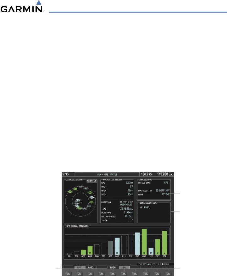
The Satellite Based Augmentation System (SBAS) provides increased navigation accuracy when available. SBAS can be enabled or disabled manually on the GPS Status Page.
SBAS Status
SBAS SELECTION Box
- WAAS Enable/Disable
RAIM Softkey |
|
|
|
SBAS Softkey |
|
|
|
||
(displays RAIM PREDICTION) |
|
|
|
(displays SBAS Selection) |
|
|
|
|
|
Figure 5-98 |
SBAS Display - Active |
|||
190-00498-03 Rev.A |
Garmin G1000 Pilot’s Guide for Cessna Nav III |
5-107 |
FLIGHT MANAGEMENT
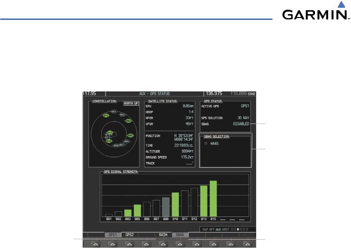
Enabling/Disabling SBAS:
1)Select the AUX-GPS Status Page.
2)Press the FMS Knob. The SBAS SELECTION ‘WAAS’ field is highlighted.
3)Press the ENT Key to disable SBAS. Press the ENT Key again to enable SBAS.
SBAS Status
SBAS SELECTION Box
- WAAS Enable/Disable
RAIM Softkey |
|
|
SBAS Softkey |
(displays RAIM PREDICTION) |
|
|
(displays SBAS Selection) |
Figure 5-99 |
SBAS Display - Disabled |
||
5-108 |
Garmin G1000 Pilot’s Guide for Cessna Nav III |
190-00498-03 Rev.A |
FLIGHT MANAGEMENT
5.11 NAVIGATING A FLIGHT PLAN
The following discussion is an example of navigating a flight plan with an LPV approach using the WAAS capable GPS system while the G1000 provides vertical guidance through descents. A flight plan with an LNAV approach would be navigated in much the same way, but would not include vertical guidance when the final approach course is active.
 NOTE: Thefollowingexampleflightplanisforinstructionalpurposesonly. Alldatabaseinformationdepicted
should be considered not current.
The example is a flight plan from KMKC to KCOS filed using the TIFTO2 departure, various Victor Airways, and the DBRY1 arrival with the transition at TBE. The flight plan includes an enroute altitude of 12,000 feet, an LPV (WAAS) approach selected for runway 35R, and a missed approach executed at the Missed Approach Point (MAP). A few enroute changes are demonstrated.
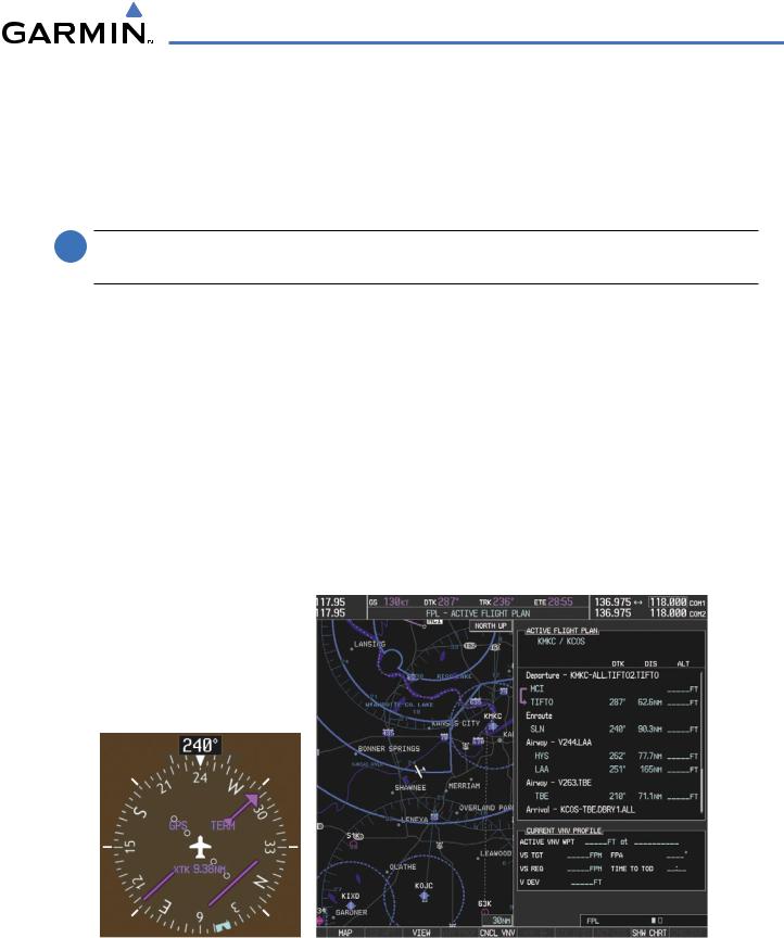
1)Prior to departure, the TIFTO2 departure, the airways, and the DBRY1 arrival at KCOS are loaded. See the Procedures section for loading departures and arrivals. Note the magenta arrow in Figure 5-101 indicating the active departure leg.
After takeoff,ATC assigns a heading of 240º.
2)Figure 5-100 shows the aircraft on the assigned heading of 240º. ‘TERM’ (Terminal) is the current CDI flight phase displayed on the HSI indicating 1.0 nm CDI scaling.
Figure 5-100 Assigned Heading of 240º
190-00498-03 Rev.A |
Garmin G1000 Pilot’s Guide for Cessna Nav III |
5-109 |
FLIGHT MANAGEMENT
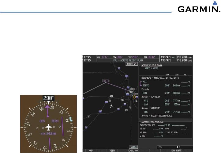
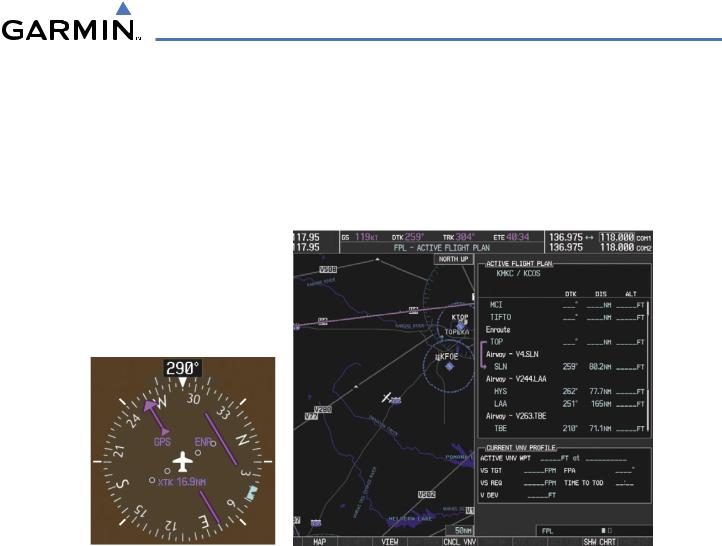
3)ATC now assigns routing to joinV4. A heading of 290º is assigned to interceptV4. The aircraft turns to heading 290° as seen in Figure 5-101.
Figure 5-101 Assigned Heading of 290º
4)Enter V4 into the flight plan.
a)Press the FMS Knob to activate the cursor.
5-110 |
Garmin G1000 Pilot’s Guide for Cessna Nav III |
190-00498-03 Rev.A |
FLIGHT MANAGEMENT
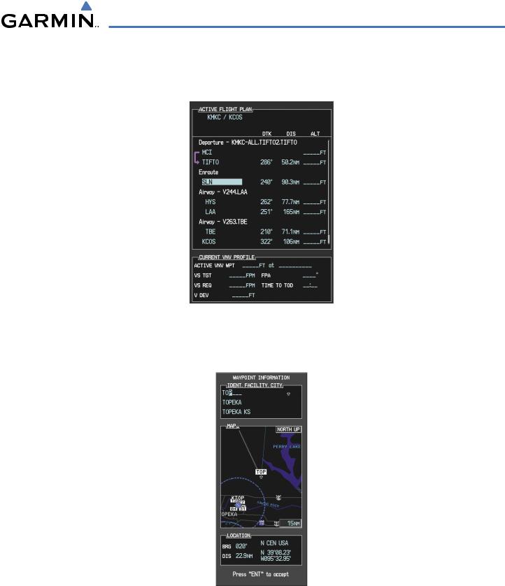
b)The desired entry point for V4 (TOP) must be entered. Turn the large FMS Knob to highlight the desired flight plan insertion point (SLN) as shown in Figure 5-103. When the V4 entry point (TOP) is inserted, it is placed immediately above the highlighted waypoint (SLN).
Figure 5-102 Begin Adding V4 to the Flight Plan
c)Turn the small FMS Knob to display the Waypoint Information Window. Enter the desired entry point for V4, Topeka VOR (TOP), as shown in Figure 5-103.
Figure 5-103 Entering V4 Entry Point
190-00498-03 Rev.A |
Garmin G1000 Pilot’s Guide for Cessna Nav III |
5-111 |
FLIGHT MANAGEMENT
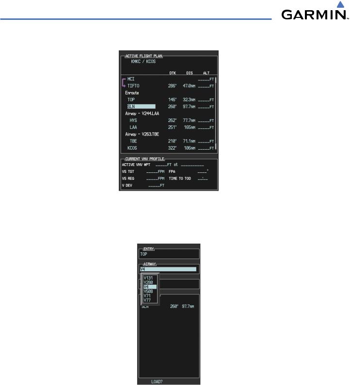
d) Press the ENT Key. TOP is inserted into the flight plan as in Figure 5-105.
Figure 5-104 TOP Inserted into the Flight Plan
e)With SLN still highlighted as in Figure 5-104, turn the small FMS Knob clockwise. The Waypoint Information Page is displayed and the LD AIRWY Softkey is now available.
f)Press the LD AIRWY Softkey to display the list of available airways for TOP as seen in Figure 5-106.
Figure 5-105 List of Available Airways for TOP
g) Turn either FMS Knob to highlight V4 in the list as seen in Figure 5-105.
5-112 |
Garmin G1000 Pilot’s Guide for Cessna Nav III |
190-00498-03 Rev.A |
FLIGHT MANAGEMENT
h) Press the ENT Key. The list of available exits for V4 is now displayed as in Figure 5-106.
Figure 5-106 List of Available Exits for V4
i)If necessary, turn either FMS Knob to select the desired exit. In this case Salina VOR (SLN) is selected as in Figure 5-106.
j)Press the ENT Key. The selected airway and exit are displayed, and the prompt “LOAD?” highlighted as in Figure 5-107.
Figure 5-107 Ready to Load V4
k) Press the ENT Key.
190-00498-03 Rev.A |
Garmin G1000 Pilot’s Guide for Cessna Nav III |
5-113 |
FLIGHT MANAGEMENT
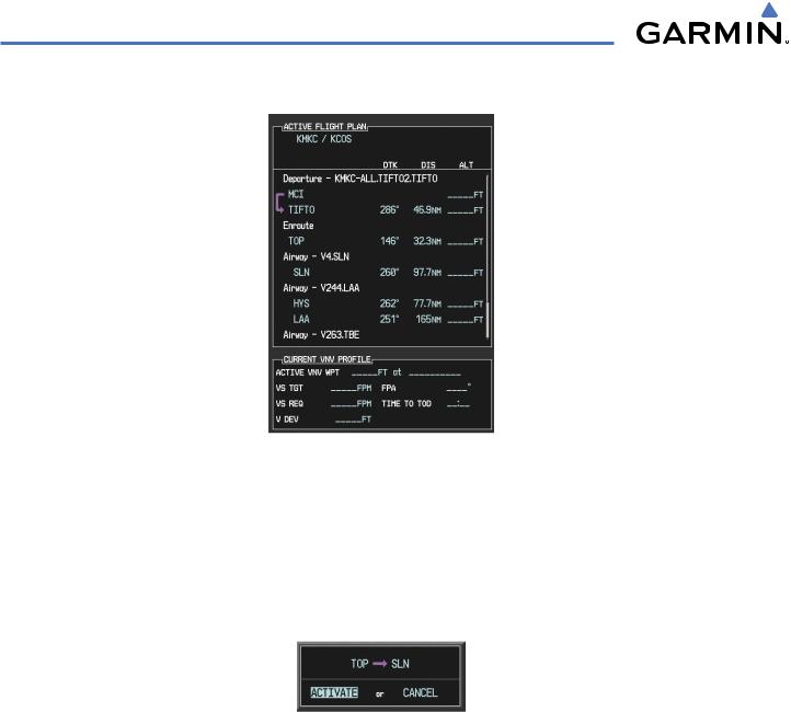
l) V4 is now loaded into the flight plan as shown in Figure 5-108.
Figure 5-108 V4 is Loaded in the Flight Plan
5)Making V4 the active leg of the flight plan.
a)Press the FMS Knob to activate the cursor.
b)Turn the large FMS Knob to highlight SLN. The TO waypoint of the leg is selected in order to activate the leg.
c)Press the ACT LEG Softkey. The confirmation window is now displayed as in Figure 5-109. Note the TOP to SLN leg is actually part of V4.
Figure 5-109 Comfirm Active Leg
5-114 |
Garmin G1000 Pilot’s Guide for Cessna Nav III |
190-00498-03 Rev.A |
FLIGHT MANAGEMENT
d)Verify the displayed leg is the desired leg and press the ENT Key. Note in Figure 5-110, the magenta arrow in the flight plan window and magenta line on the map indicating V4 is now the active flight plan leg. Note the phase of flight remained in Terminal (TERM) mode up to this point because a departure leg was active. Since a leg after the departure is now active, the current CDI flight phase is ENR (Enroute) and CDI scaling has changed to 2.0 nm.
Figure 5-110 V4 Now Active Leg
6)The aircraft continues on heading 290º. When crosstrack distance is less than 2.0 nm,the XTK disappears from the HSI and the CDI is positioned on the last dot indicating a 2.0 nm distance from the centerline of the next course.
190-00498-03 Rev.A |
Garmin G1000 Pilot’s Guide for Cessna Nav III |
5-115 |

FLIGHT MANAGEMENT
7) As the CDI approaches center, the aircraft turns onto the active leg as seen in Figure 5-111.
Figure 5-111 Turn on to Active Leg
8)At SLN,Victor Airway 244 (V244) is intercepted. Turn prompts are displayed in the PFD Navigation Status Box as seen in Figure 5-112.
Figure 5-112 Turn to Intercept V244
5-116 |
Garmin G1000 Pilot’s Guide for Cessna Nav III |
190-00498-03 Rev.A |
FLIGHT MANAGEMENT
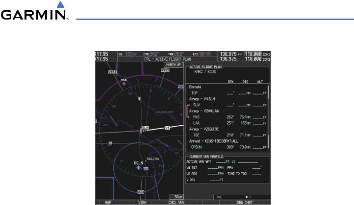
9) As seen in Figure 5-113,V244 is now the active flight plan leg.
Figure 5-113 V244 Now Active Leg
190-00498-03 Rev.A |
Garmin G1000 Pilot’s Guide for Cessna Nav III |
5-117 |
FLIGHT MANAGEMENT
10) At Lamar VOR (LAA) V263 is intercepted. See Figure 5-114.
Figure 5-114 HYS to LAA Leg Active
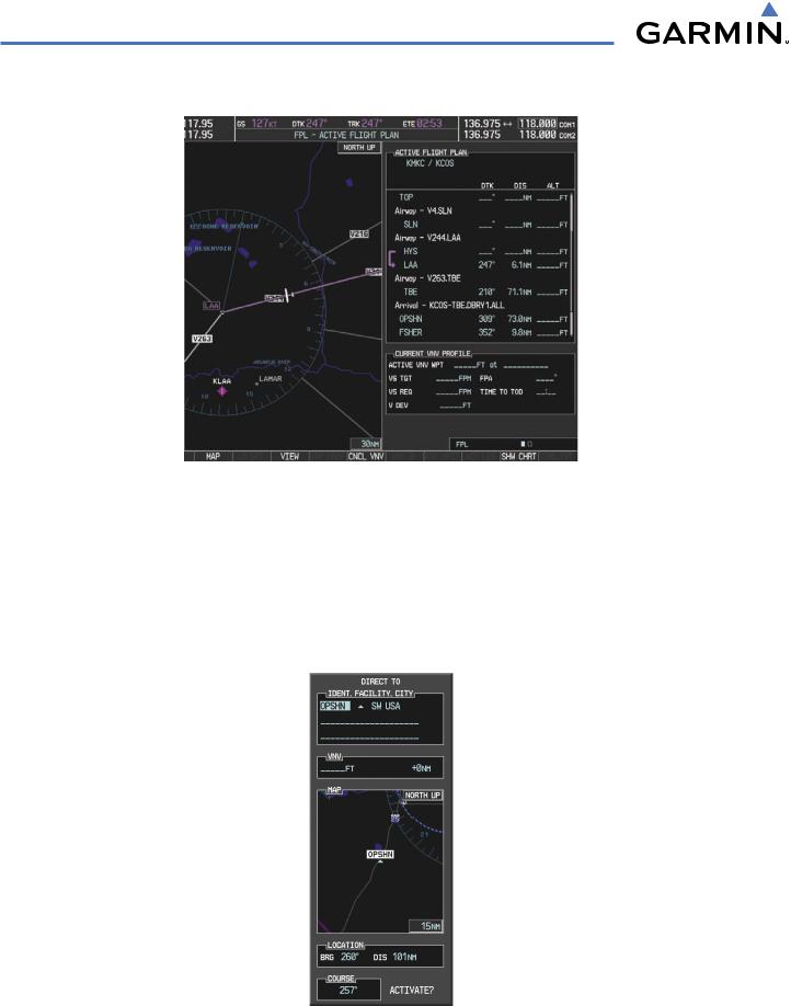
11)ATC grants clearance to proceed direct to the OPSHN intersection to begin the arrival procedure. ATC advises to expect an altitude of 10,000 feet at OPSHN.
a)Press the FMS Knob to activate the cursor.
b)Turn the large FMS Knob to select OPSHN in the flight plan list.
c)Press the Direct-to ( ) Key. The Direct-to Window is now displayed as shown in Figure 5-115.
Figure 5-115 Direct To OPSHN
5-118 |
Garmin G1000 Pilot’s Guide for Cessna Nav III |
190-00498-03 Rev.A |

FLIGHT MANAGEMENT
d) Turn the large FMS Knob to place the cursor in the VNV altitude field as shown in Figure 5-116.
Figure 5-116 Enter VNV Altitude
e)An altitude of 10,000 feet is entered as requested by ATC.
f)Press the ENT Key. The cursor is now displayed in the VNV offset field as shown in Figure 5-117.
Figure 5-117 Enter VNV Offset Distance
g)Enter the offset, or distance from the waypoint at which to reach the selected altitude. In this case, three miles prior to OPSHN is entered. In other words, the G1000 gives vertical guidance so the aircraft arrives at an altitude of 10,000 feet three miles prior to OPSHN.
190-00498-03 Rev.A |
Garmin G1000 Pilot’s Guide for Cessna Nav III |
5-119 |
FLIGHT MANAGEMENT
h)Press the ENT Key twice to activate the direct-to. Note,in Figure 5-118,the magenta arrow indicating the directto OPSHN after the offset waypoint for OPSHN. The preceding offset waypoint indicates the offset distance and altitude that were previously entered. The remaining waypoints in the loaded arrival procedure have no database specified altitudes,therefore,dashes are displayed. Keep the CDI centered and maintain a track along the magenta line to OPSHN.
Note the Direct-to waypoint is within the loaded arrival procedure, therefore, phase of flight scaling for theCDI changes to Terminal Mode and is annunciated by displaying ‘TERM’ on the HSI.
 NOTE: If the loaded arrival procedure has waypoints with altitude constraints retrieved from the database to be used as is, the altitude must be manually accepted by placing the cursor over the desired altitude, then pressing the ENT Key. The altitude is now displayed as light blue meaning it is used by the system to determine vertical speed and deviation guidance.
Figure 5-118 Direct-to Active
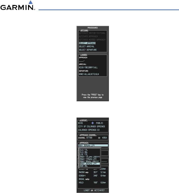
12)The aircraft is proceeding to OPSHN. The expected approach is the RNAV LPV approach to runway 35R, so it is selected.
a)Press the PROC Key to display the Procedures Window.
5-120 |
Garmin G1000 Pilot’s Guide for Cessna Nav III |
190-00498-03 Rev.A |
FLIGHT MANAGEMENT
b) ‘SELECT APPROACH’ should be highlighted as shown in Figure 5-119.
Figure 5-119 Proceudures Window
c) Press the ENT Key. A list of available approaches for the destination airport is displayed as in Figure 5-120.
Figure 5-120 List of Available Approaches
d) Turn either FMS Knob to select the LPV approach for 35R as shown in Figure 5-120.
190-00498-03 Rev.A |
Garmin G1000 Pilot’s Guide for Cessna Nav III |
5-121 |
FLIGHT MANAGEMENT
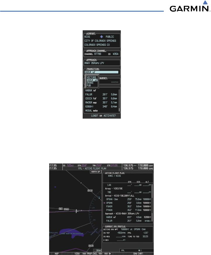
e) Press the ENT Key. A list of available transitions for the selected approach is displayed as in Figure 5-121.
Figure 5-121 List of Available Transitions
f)Turn either FMS Knob to select the desired transition. In this case, the Initial Approach Fix (IAF) at HABUK is used.
g)Press the ENT Key.
h)With ‘LOAD?’ highlighted, again press the ENT Key. The selected approach is added to the flight plan as seen in Figure 5-122.
Figure 5-122 Loaded Approach
5-122 |
Garmin G1000 Pilot’s Guide for Cessna Nav III |
190-00498-03 Rev.A |
FLIGHT MANAGEMENT
13)Note the altitude constraints associated with each of the approach waypoints as seen in Figure 5-123. These altitudes are loaded from the database and are displayed as light blue text, indicating these values are “designated” for use in computing vertical deviation guidance.
Note: To no longer use the displayed altitude for calculating vertical deviation guidance, perform the following:
a) Press the FMS Knob to activate the cursor.
b) Turn the small FMS Knob to highlight the desired altitude. c) Press the CLR Key.
d) Press the FMS Knob to deactivate the cursor.
After making the altitude “non-designated”, it is displayed as white text.
Altitude constraint values associated with the Final Approach Fix (FAF) and waypoints beyond the FAF cannot be designated for vertical guidance. These altitude values are always displayed as white text, as in Figure 5- 123. Vertical guidance from the FAF and on to the Missed Approach Point (MAP) is given using the WAAS GPS altitude source, therefore, the displayed altitude values are for reference only.
Figure 5-123 Vertical Guidance is Active to the FAF
190-00498-03 Rev.A |
Garmin G1000 Pilot’s Guide for Cessna Nav III |
5-123 |
FLIGHT MANAGEMENT
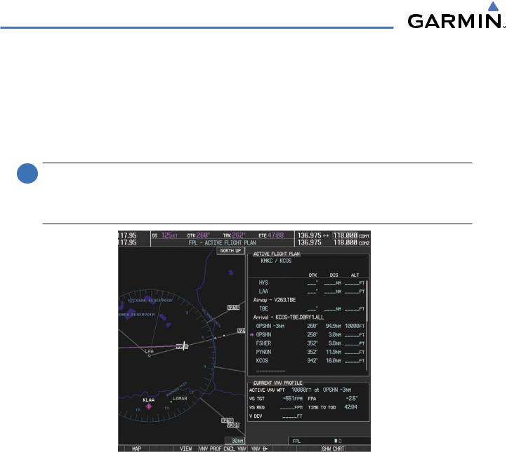
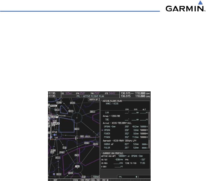
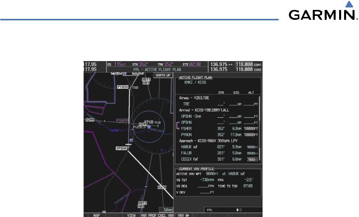
14)As the aircraft approaches OPSHN, it may be desirable to adjust the speed, or steepness of the upcoming descent. The default Flight Path Angle (FPA) is -3.0 degrees and a required vertical speed is computed to maintain the -3.0 FPA. To change the vertical flight path, perform the following steps.
a)Press the VNV PROF Softkey to place the cursor in the target vertical speed field (VS TGT) as shown in Figure 5-124.
b)At this point, the descent vertical speed can be selected, or the FPA can be selected. Turn the large FMS Knob to select the desired selection field, then turn the small FMS Knob to enter the desired value.
Note the information now displayed in the‘CURRENTVNV PROFILE’ box. Also,note the offset waypoint (orange box) and gray circle are now displayed on the map. The gray circle marks the Top of Descent (TOD). In this example, vertical guidance is provided at the TOD that results in a -3.0 degree FPA descent to an altitude of 10,000 feet upon reaching the offset waypoint.
Figure 5-124 Adjusting the Descent
c) Press the ENT Key.
5-124 |
Garmin G1000 Pilot’s Guide for Cessna Nav III |
190-00498-03 Rev.A |

FLIGHT MANAGEMENT
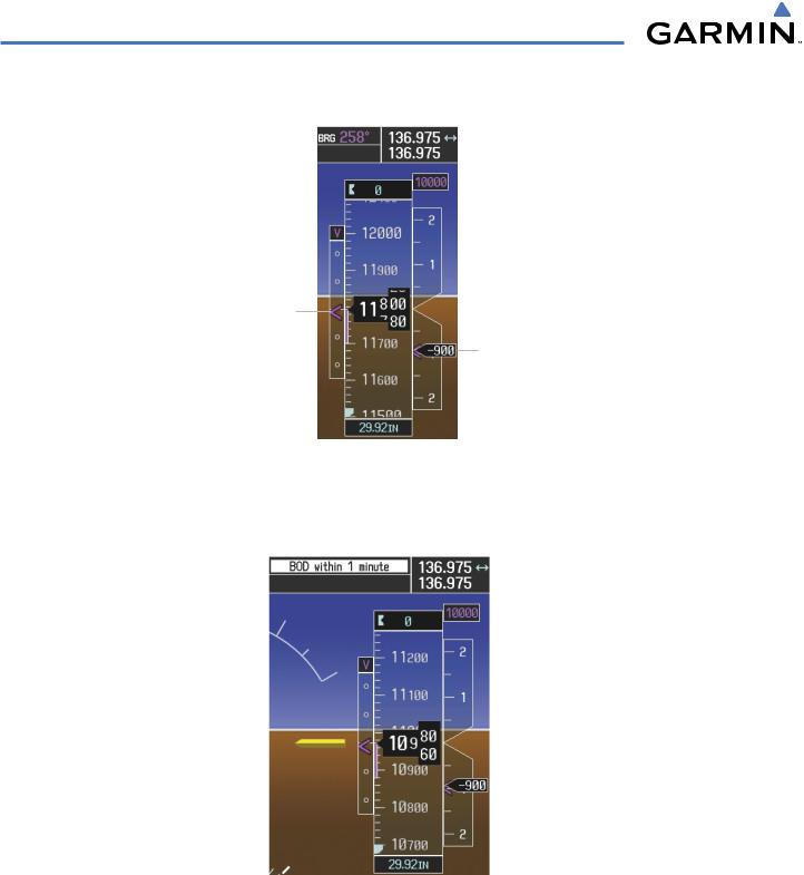
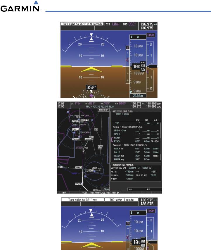
15)As seen in Figure 5-125, the aircraft is approachingTOD. Note the target vertical speed required to reached the selected altitude. TheVertical Deviation Indicator (VDI) and the RequiredVertical Speed Indicator (RVSI) are now displayed on the PFD as shown in Figure 5-126.
Figure 5-125 Approaching Top of Descent (TOD)
Target Altitude
Vertical Deviation
Indicator (VDI)
Required Vertical Speed Indicator (RVSI)
Figure 5-126 VDI & RVSI Upon Reaching Top of Descent (TOD)
190-00498-03 Rev.A |
Garmin G1000 Pilot’s Guide for Cessna Nav III |
5-125 |
FLIGHT MANAGEMENT
16)Upon reachingTOD, a descent vertical speed is established which places theVSI pointer in line with the RVSI as shown in Figure 5-127.
Keep Vertical Deviation Pointer Centered
Align Actual Vertical Speed with
Required Vertical Speed
Figure 5-127 VDI & RVSI Showing Correctly Established Descent
17)When the aircraft is one minute from the bottom of descent (BOD) it is annunciated as shown in Figure 5-128. Upon reaching the offset waypoint for OPSHN, the aircraft is at 10,000 feet.
Figure 5-128 Approaching Bottom of Descent (BOD) at OPSHN Offset Waypoint
5-126 |
Garmin G1000 Pilot’s Guide for Cessna Nav III |
190-00498-03 Rev.A |

FLIGHT MANAGEMENT
18)The aircraft is approaching OPSHN. The upcoming turn and next heading are annunciated at the top left of the PFD as seen in Figure 5-129. Initiate the turn and maneuver the aircraft on a track through the turn radius to intercept the magenta line for the OPSHN to FSHER leg and center the CDI.
Figure 5-129 Turn to intercept OPSHN to FSHER Leg
190-00498-03 Rev.A |
Garmin G1000 Pilot’s Guide for Cessna Nav III |
5-127 |
FLIGHT MANAGEMENT
19)After passing OPSHN, the next leg of the arrival turns magenta as shown in Figure 5-130. The magenta arrow in the flight plan list now indicates the OPSHN to FSHER leg of the arrival procedure is now active.
Figure 5-130 Tracking the OPSHN to FSHER Leg
20)The flight continues through the arrival procedure to PYNON (see Figure 5-131). At a point 31 nm from the destination airport, the phase of flight scaling for the CDI changes to Terminal Mode and is annunciated by displaying ‘TERM’ on the HSI.
A descent to HABUK is in the next leg. Note the TOD point on the map. Annunciations for the upcoming turn and descent, as well as the VDI and RVSI, appear on the PFD as the flight progresses.
5-128 |
Garmin G1000 Pilot’s Guide for Cessna Nav III |
190-00498-03 Rev.A |
FLIGHT MANAGEMENT
Figure 5-131 Approaching PYNON
190-00498-03 Rev.A |
Garmin G1000 Pilot’s Guide for Cessna Nav III |
5-129 |
FLIGHT MANAGEMENT
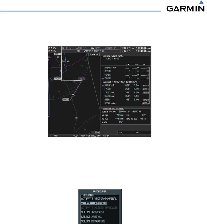
21)Upon passing PYNON the approach procedure automatically becomes active. The approach may be activated at any point to proceed directly to the IAF. In this example, the aircraft has progressed through the final waypoint of the arrival and the flight plan has automatically sequenced to the IAF as the active leg, activating the approach procedure (see Figure 5-132).
Figure 5-132 Approach is Now Active
Note: To manually activate the approach procedure, perform the following steps:
a)Press the PROC Key.
b)Turn the large FMS Knob to highlight ‘ACTIVATE APPROACH’ as shown in Figure 5-133.
c)Press the ENT Key to activate the approach.
Figure 5-133 Manually Activate Approach
5-130 |
Garmin G1000 Pilot’s Guide for Cessna Nav III |
190-00498-03 Rev.A |
FLIGHT MANAGEMENT
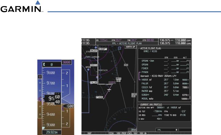
22)The IAF is the next waypoint. At the TOD, establish a descent vertical speed as previously discussed in Step 16. The aircraft altitude is 9,000 feet upon reaching HABUK.
Figure 5-134 Descending Turn to the Initial Approach Fix (IAF)
190-00498-03 Rev.A |
Garmin G1000 Pilot’s Guide for Cessna Nav III |
5-131 |
FLIGHT MANAGEMENT
23)After crossing FALUR the next waypoint is the FAF. The flight phase changes to LPV on the HSI indicating the current phase of flight is inApproach Mode and the approach type is LPV. CDI scaling changes accordingly and is used much like a localizer when flying an ILS approach. The RVSI is no longer displayed and the VDI changes to the Glidepath Indicator (as shown in Figure 5-135) when the final approach course becomes active.
Figure 5-135 Descending to the FAF
The descent continues through the FAF (CEGIX) using the Glidepath Indicator, as one would use a glideslope indicator,to obtain an altitude“AT”7,800 feet at the FAF. Note the altitude restriction lines over and under (At) the altitude in the ‘ALT’ field in Figure 5-135.
5-132 |
Garmin G1000 Pilot’s Guide for Cessna Nav III |
190-00498-03 Rev.A |
FLIGHT MANAGEMENT
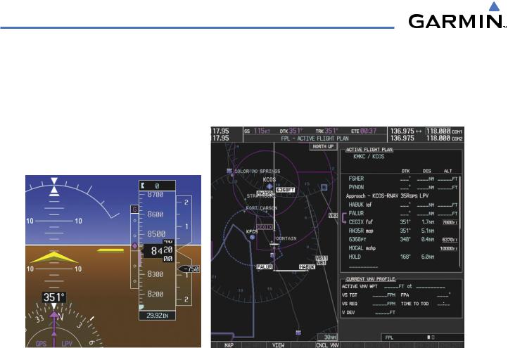
24)After crossing CEGIX, the aircraft continues following the glidepath to maintain the descent to “AT or ABOVE” 6,370 feet at the MissedApproach Point (MAP) (RW35R) as seen in Figure 5-136.
Figure 5-136 Descending to the Missed Approach Point
In this missed approach procedure, the fix immediately following the MAP (in this case ‘6368FT’) is not part of the published procedure. It is simply a fix that defines a leg which guides the aircraft along the runway centerline until the required altitude to make the first turn on the missed approach is exceeded. In this case, if the aircraft altitude is below the specified altitude (6,368 feet) after crossing the MAP, a direct-to is established to this fix until an altitude of 6,368 feet reached. After reaching 6,368 feet, a direct-to is established to the published fix (in this case MOGAL). If the aircraft altitude is above the specified altitude after crossing the MAP, a direct-to is established to the published fix (MOGAL) to begin the missed approach procedure. The altitude constraint value defaults to 400 feet AGL when the fix is not part of the published procedure.
In some missed approach procedures this altitude fix may be part of the published procedure. For example, the procedure dictates a climb to 5,500 feet,then turn left and proceed to the MissedApproach Hold Point (MAHP). In this case,the altitude fix would be labeled‘5500FT’. Again,if the aircraft altitude is lower than this prescribed altitude, a direct-to is established to this fix when the missed approach procedure is activated.
190-00498-03 Rev.A |
Garmin G1000 Pilot’s Guide for Cessna Nav III |
5-133 |
FLIGHT MANAGEMENT
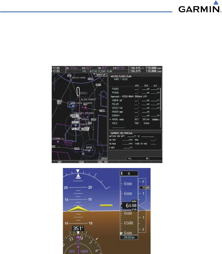
25)Upon reaching the MAP, it is decided to execute a missed approach. Automatic waypoint sequencing is suspended past the MAP. Press the SUSP Softkey on the PFD to resume automatic waypoint sequencing through the missed approach procedure.
A direct-to is initiated to MOGAL, which is the Missed Approach Hold Point (MAHP) as seen in Figure 5-137. The aircraft is climbing to 10,000 feet. The CDI flight phase now changes from LPV to MAPR as seen on the HSI.
Figure 5-137 Missed Approach Active
5-134 |
Garmin G1000 Pilot’s Guide for Cessna Nav III |
190-00498-03 Rev.A |
FLIGHT MANAGEMENT
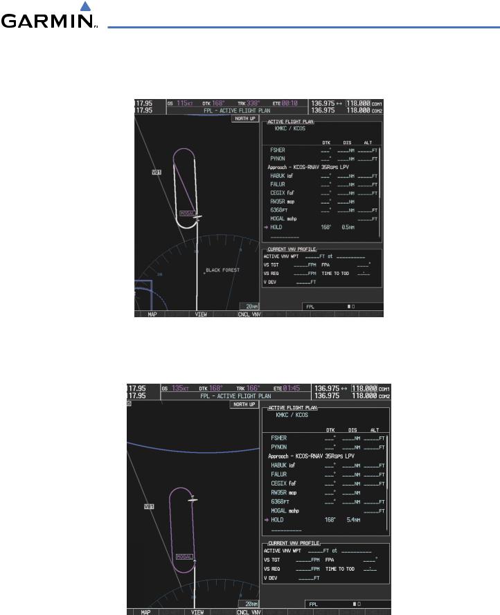
26)The aircraft continues climbing to “AT or ABOVE” 10,000 feet at MOGAL. A holding pattern is established at the MAHP (MOGAL) as shown in Figure 5-138.
Figure 5-138 Establishing the Holding Pattern
27) The aircraft maintains 10,000 feet while following the magenta line through the hold as in Figure 5-139.
Figure 5-139 Hold Established
190-00498-03 Rev.A |
Garmin G1000 Pilot’s Guide for Cessna Nav III |
5-135 |