

FLIGHT INSTRUMENTS
2.4 ABNORMAL OPERATIONS
ABNORMAL GPS CONDITIONS
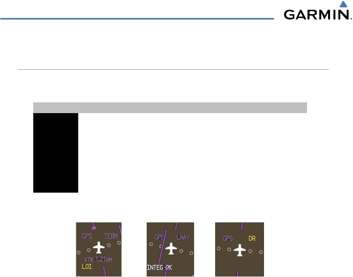
The annunciations listed in Table 2-3 can appear on the HSI when abnormal GPS conditions occur; see Figure 2-41 for examples. Refer to the Flight Management Section for more information on Dead Reckoning Mode.
Annunciation |
Location |
Description |
|
LOI |
Lower left of |
Loss of Integrity Monitoring–GPS integrity is insufficient for the current |
|
aircraft symbol |
phase of flight |
||
|
|||
WARN |
Lower left of |
Warning–RAIM function detects excessive GPS position errors |
|
|
aircraft symbol |
|
|
INTEG OK |
Lower left of |
Integrity OK–GPS integrity has been restored to within normal limits |
|
aircraft symbol |
(annunciation displayed for 5 seconds) |
||
|
|||
DR |
Upper right of |
DeadReckoning–SystemisusingprojectedpositionratherthanGPSposition |
|
aircraft symbol |
to compute navigation data and sequence active flight plan waypoints |
||
|
Table 2-3 Abnormal GPS Conditions Annunciated on HSI
Figure 2-41 Example HSI Annunciations
Dead Reckoning Mode causes the CDI to be removed from the display (when GPS is the selected navigation source) and the following items on the PFD to be shown in yellow:
•Current Track Bug
•Wind Data (calculated based on GPS information)
•Distances in the Bearing Information windows
•GPS bearing pointers
These items should be verified when operating in Dead Reckoning Mode.
2-30 |
Garmin G1000 Pilot’s Guide for Cessna Nav III |
190-00498-03 Rev.A |
FLIGHT INSTRUMENTS
UNUSUAL ATTITUDES
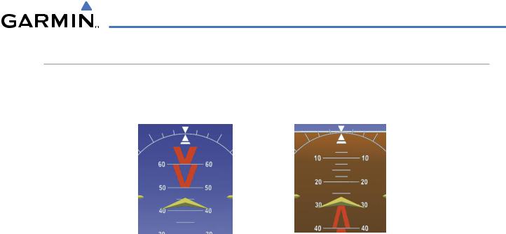
When the aircraft enters an unusual pitch attitude, red extreme pitch warning chevrons pointing toward the horizon are displayed on the Attitude Indicator, starting at 50˚ above and 30˚ below the horizon line.
Nose High |
Nose Low |
Figure 2-42 Pitch Attitude Warnings
If pitch exceeds +30˚/-20˚ or bank exceeds 65˚, some information displayed on the PFD is removed. The Altimeter and Airspeed, Attitude, Vertical Speed, and Horizontal Situation indicators remain on the display and the Bearing Information, Alerts, and Annunciation windows can be displayed during such situations. The following information is removed from the PFD (and corresponding softkeys are disabled) when the aircraft experiences unusual attitudes:
•Traffic Annunciations
•AFCS Annunciations
•Flight director Command Bars
•Inset Map
•Outside Air Temperature (OAT)
•DME Information Window
•Wind data
•Selected Heading Box
•Selected Course Box
•Transponder Status Box
•System Time
•PFD Setup Menu
•Windows displayed in the lower right corner of the PFD:
–Timer/References
–Nearest Airports
–Flight Plan
–Alerts
–Procedures
–DME Tuning
•Minimum Descent Altitude/ Decision Height readout
•Vertical Deviation, Glideslope, and Glidepath Indicators
•Altimeter Barometric Setting
•Selected Altitude
•VNV Target Altitude
190-00498-03 Rev.A |
Garmin G1000 Pilot’s Guide for Cessna Nav III |
2-31 |

FLIGHT INSTRUMENTS
BLANK PAGE
2-32 |
Garmin G1000 Pilot’s Guide for Cessna Nav III |
190-00498-03 Rev.A |