

- •Section 1 System Overview
- •1.1 System Description
- •1.2 Line Replaceable Units (LRU)
- •1.3 G1000 Controls
- •PFD/MFD Controls
- •Audio Panel Controls
- •1.4 Secure Digital (SD) Cards
- •1.5 System Power-up
- •1.6 System Operation
- •Normal Display Operation
- •Reversionary Display Operation
- •AHRS Operation
- •G1000 System Annunciations
- •Softkey Function
- •GPS Receiver Operation
- •1.7 Accessing G1000 Functionality
- •Menus
- •MFD Page Groups
- •MFD System Pages
- •1.8 Display Backlighting
- •Automatic Adjustment
- •Manual Adjustment
- •Section 2 Flight Instruments
- •2.1 Flight Instruments
- •Airspeed Indicator
- •Attitude Indicator
- •Altimeter
- •Vertical Speed Indicator (VSI)
- •Vertical Deviation
- •Horizontal Situation Indicator (HSI)
- •Course Deviation Indicator (CDI)
- •2.2 Supplemental Flight Data
- •Outside Air Temperature
- •Wind Data
- •Vertical Navigation (VNV) Indications
- •2.3 PFD Annunciations and Alerting Functions
- •G1000 System Alerting
- •Marker Beacon Annunciations
- •Traffic Annunciation
- •TAWS Annunciations
- •Altitude Alerting
- •Low Altitude Annunciation
- •Minimum Descent Altitude/Decision Height Alerting
- •2.4 Abnormal Operations
- •Abnormal GPS Conditions
- •Unusual Attitudes
- •Section 3 Engine Indication System (EIS)
- •3.1 Engine Display
- •3.2 Lean Display
- •Normally-aspirated Aircraft
- •Turbocharged Aircraft
- •3.3 System Display
- •Section 4 audio panel and CNS
- •4.1 Overview
- •MFD/PFD Controls and Frequency Display
- •Audio Panel Controls
- •4.2 COM Operation
- •COM Transceiver Selection and Activation
- •COM Transceiver Manual Tuning
- •Quick-Tuning and Activating 121.500 MHz
- •Auto-tuning the COM Frequency
- •Frequency Spacing
- •Automatic Squelch
- •Volume
- •4.3 NAV Operation
- •NAV Radio Selection and Activation
- •NAV Receiver Manual Tuning
- •Auto-tuning a NAV Frequency from the MFD
- •Marker Beacon Receiver
- •DME Tuning (Optional)
- •4.4 GTX 33 Mode S Transponder
- •Transponder Controls
- •Transponder Mode Selection
- •Entering a Transponder Code
- •IDENT Function
- •Flight ID Reporting
- •4.5 Additional Audio Panel Functions
- •Power-Up
- •Mono/Stereo Headsets
- •Speaker
- •Intercom
- •Passenger Address (PA) System
- •Clearance Recorder and Player
- •Entertainment Inputs
- •4.6 Audio Panel Preflight Procedure
- •4.7 Abnormal Operation
- •Stuck Microphone
- •COM Tuning Failure
- •Audio Panel Fail-Safe Operation
- •Reversionary Mode
- •Section 5 Flight Management
- •5.1 Introduction
- •Navigation Status Box
- •5.2 Using Map Displays
- •Map Orientation
- •Map Range
- •Map Panning
- •Measuring Bearing and Distance
- •Topography
- •Map Symbols
- •Airways
- •Track Vector
- •Wind Vector
- •Nav Range Ring
- •Fuel Range Ring
- •5.3 Waypoints
- •Airports
- •Intersections
- •NDBs
- •VORs
- •User Waypoints
- •5.4 Airspaces
- •5.5 Direct-to-Navigation
- •5.6 Flight Planning
- •Flight Plan Creation
- •Adding Waypoints To An Existing Flight Plan
- •Adding Airways to a Flight Plan
- •Adding Procedures To A Stored Flight Plan
- •Flight Plan Storage
- •Flight Plan Editing
- •Along Track Offsets
- •Parallel Track
- •Activating a Flight Plan Leg
- •Inverting a Flight Plan
- •Flight Plan Views
- •Closest Point of FPL
- •5.7 Vertical Navigation
- •Altitude Constraints
- •5.8 Procedures
- •Departures
- •Arrivals
- •Approaches
- •5.9 Trip Planning
- •Trip Planning
- •5.10 RAIM Prediction
- •5.11 Navigating a Flight Plan
- •5.12 Abnormal Operation
- •Section 6 Hazard Avoidance
- •6.1 XM Satellite Weather
- •Activating Services
- •Using XM Satellite Weather Products
- •6.2 WX-500 Stormscope (Optional)
- •Setting Up Stormscope on the Navigation Map
- •Selecting the Stormscope Page
- •6.3 Terrain Proximity
- •Displaying Terrain Proximity Data
- •Terrain Proximity Page
- •6.4 TAWs (Optional)
- •Displaying TAWS Data
- •TAWS Page
- •TAWS Alerts
- •System Status
- •6.5 Traffic Information Service (TIS)
- •Displaying TRAFFIC Data
- •Traffic Map Page
- •TIS Alerts
- •System Status
- •6.6 Traffic Advisory System (TAS) (Optional)
- •TAS Symbology
- •Operation
- •Altitude Display
- •Traffic Map Page Display Range
- •TAS Alerts
- •System Status
- •6.7 ADS-B Traffic (Optional)
- •Section 7 Automatic Flight Control System
- •7.2 Flight Director Operation
- •Activating the Flight Director
- •AFCS Status Box
- •Command Bars
- •Flight Director Modes
- •7.3 Vertical Modes
- •Pitch Hold Mode (PIT)
- •Selected Altitude capture Mode (ALTs)
- •Altitude hold mode (alt)
- •Vertical Speed Mode (VS)
- •Flight Level Change Mode (FLC)
- •Vertical Navigation Modes (VPTH, ALTV)
- •Glidepath Mode (GP) (waas only)
- •Glideslope Mode (GS)
- •Go Around (GA) Mode
- •7.4 Lateral Modes
- •Roll Hold Mode (ROL)
- •Heading Select Mode (HDG)
- •Navigation mode (GPS, VOR, LOC)
- •Approach mode (GPS, VAPP, LOC)
- •Backcourse Mode (BC)
- •7.5 Autopilot Operation
- •Engaging the Autopilot
- •Control Wheel Steering
- •Disengaging the Autopilot
- •7.6 Example Procedures
- •Departure
- •Intercepting a VOR Radial
- •Flying a Flight Plan/GPS Course
- •Descent
- •Approach
- •Go Around/Missed Approach
- •7.7 AFCS Annunciations and Alerts
- •AFCS Status Alerts
- •Overspeed Protection
- •Section 8 Additional Features
- •8.1 SafeTaxi
- •SafeTaxi Cycle Number and Revision
- •8.2 ChartView
- •ChartView Softkeys
- •Terminal Procedures Charts
- •Chart Options
- •Day/Night View
- •ChartView Cycle Number and Expiration Date
- •8.3 FliteCharts
- •FliteCharts Softkeys
- •Terminal Procedures Charts
- •Chart Options
- •Day/Night View
- •FliteCharts Cycle Number and Expiration Date
- •8.4 XM Radio Entertainment (Optional)
- •Activating XM Satellite Radio Services
- •Using XM Radio
- •Automatic Audio Muting
- •8.5 Scheduler
- •8.5 Abnormal Operation
- •Annunciations and Alerts
- •Alert Level Definitions
- •Nav III Aircraft Alerts
- •CO Guardian Messages
- •G1000 System Annunciations
- •Other G1000 Aural Alerts
- •G1000 System Message Advisories
- •AFCS Alerts
- •TAWS ALERTS
- •TAWS System Status Annunciations
- •SD Card Use
- •Jeppesen Databases
- •Garmin Databases
- •Glossary
- •Frequently Asked Questions
- •General TIS Information
- •Introduction
- •TIS vs. TAS/TCAS
- •TIS Limitations
- •Map Symbols
- •Index
AUTOMATIC FLIGHT CONTROL SYSTEM
7.6 EXAMPLE PROCEDURES
 NOTE: The following example flight plan and diagrams (not to be used for navigation) in this section are for instructional purposes only and should be considered not current. Numbered portions of accompanying diagrams correspond to numbered procedure steps.
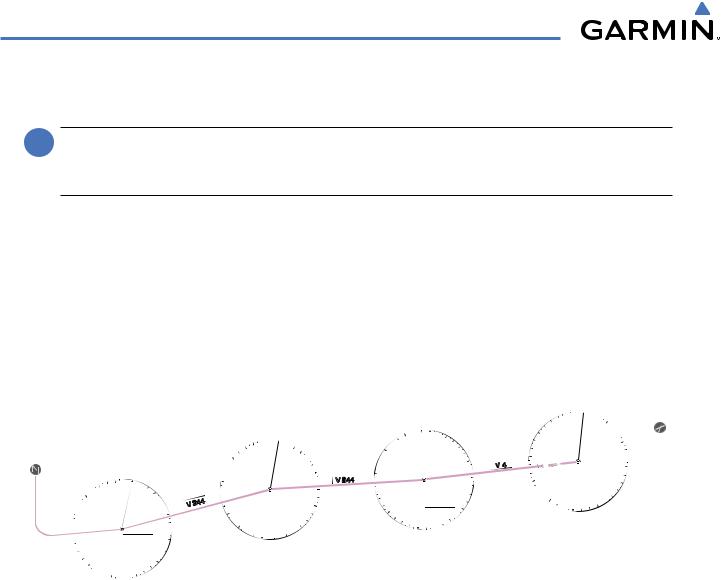
This scenario-based set of procedures (based on the example flight plan found in the Flight Management Section) shows various GFC 700 AFCS modes used during a flight. In this scenario, the aircraft departs Charles B. Wheeler Downtown Airport (KMKC), enroute to Colorado Springs Airport (KCOS). After departure, the aircraft climbs to 12,000 ft and airway V4 is intercepted, following ATC vectors.
AirwayV4isflowntoSalinaVOR(SLN)usingVORnavigation,thenairwayV244isflownusingGPSNavigation. The ILS approach for runway 35L and LPV (WAAS) approach for runway 35R are shown and a missed approach is executed.
KCOS
33 |
0 |
|
|
|
|
|
3 |
|
|
30 |
|
|
|
|
|
|
6 |
0 |
|
27 |
|
|
|
|
|
|
|
|
|
|
Hays |
9 |
|
|
|
VOR |
|
|
|
|
(HYS) |
|
|
|
|
|
12 |
|
9 |
18 |
15 |
|
|
|
|
|
24
|
0 |
|
|
33 |
|
|
|
3 |
|
30 |
|
|
|
6 |
27 |
|
|
|
Salina |
9 |
24 |
VOR |
|
(SLN) |
|
|
|
|
12 |
|
21 |
|
|
15 |
|
|
18 |
|
21 |
|
12 |
|
|
|
|
18 |
15 |
|
|
Figure 7-30 Flight Plan Overview
|
0 |
|
|
33 |
|
|
3 |
|
|
30 |
|
|
|
6 |
27 |
|
|
|
Topeka |
9 |
|
|
|
24 |
VOR |
|
(TOP) |
|
|
|
12 |
|
|
|
|
|
21 |
|
|
15 |
|
|
18 |
|
KMKC
7-32 |
Garmin G1000 Pilot’s Guide for Cessna Nav III |
190-00498-03 Rev.A |
AUTOMATIC FLIGHT CONTROL SYSTEM
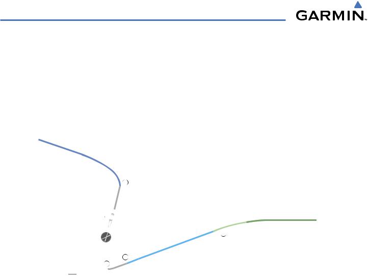
DEPARTURE
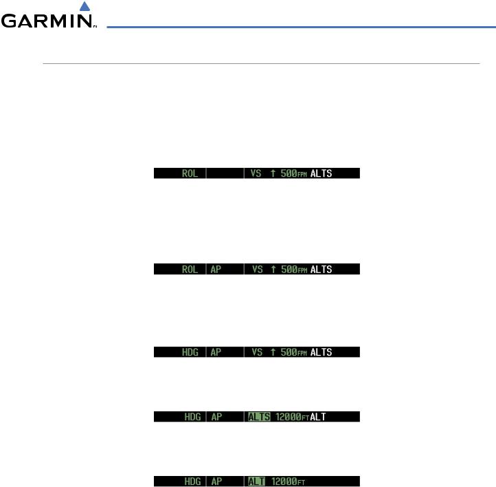
Climbing to the Selected Altitude and flying an assigned heading:
1)Before takeoff, set the Selected Altitude to 12,000 feet using the ALT Knob.
2)In this example, Vertical Speed Mode is used to capture the Selected Altitude (Pitch Hold, Vertical Speed, or Flight Level Change Mode may be used).
a)Press the VS Key to activate Vertical Speed Mode.
The Vertical Speed Reference may be adjusted after Vertical Speed Mode is selected using the NOSE UP/ NOSE DN keys or pushing the CWS Button while hand-flying the aircraft to establish a new Vertical Speed Reference.
b)Press the AP Key to engage the autopilot in a climb using Vertical Speed Mode.
3)Use the HDG Knob to set the Selected Heading, complying with ATC vectors to intercept Airway V4.
Press the HDG Key to activate Heading Select Mode while the autopilot is engaged in the climb. The autopilot follows the Selected Heading Bug on the HSI and turns the aircraft to the desired heading.
4)As the aircraft nears the Selected Altitude, the flight director transitions to Selected Altitude Capture Mode, indicated by the green ‘ALTS’ annunciation flashing for up to 10 seconds.
At 50 feet from the Selected Altitude, the green ‘ALT’ annunciation flashes for up to 10 seconds; the autopilot transitions to Altitude Hold Mode and levels the aircraft.
190-00498-03 Rev.A |
Garmin G1000 Pilot’s Guide for Cessna Nav III |
7-33 |
AUTOMATIC FLIGHT CONTROL SYSTEM
HDG |
Mode |
|
3
KMKC
2
Selected Altitude of 12,000 MSL
ALT Mode
4
Mode
VS
Figure 7-31 Departure
7-34 |
Garmin G1000 Pilot’s Guide for Cessna Nav III |
190-00498-03 Rev.A |
AUTOMATIC FLIGHT CONTROL SYSTEM
INTERCEPTING A VOR RADIAL
During climb-out, the autopilot continues to fly the aircraft in Heading Select Mode. Airway V4 to Salina VOR (SLN) should now be intercepted. Since the enroute flight plan waypoints correspond to VORs, flight director Navigation Mode using either VOR or GPS as the navigation source may be used. In this scenario, VOR Navigation Mode is used for navigation to the first VOR waypoint in the flight plan.
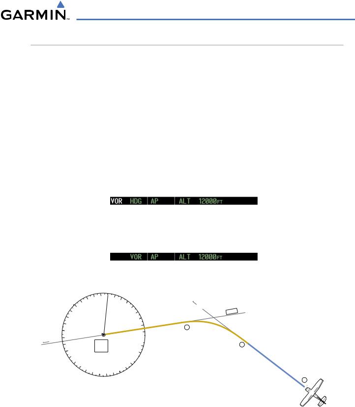
Intercepting a VOR radial:
1)Arm VOR Navigation Mode:
a)Tune the VOR frequency.
b)Press the CDI Softkey to set the navigation source to VOR.
c)Use the CRS Knob to set the Selected Course to 255°. Note that at this point, the flight director is still in Heading Select Mode and the autopilot continues to fly 290°.
d)Press the NAV Key. This arms VOR Navigation Mode and the white ‘VOR’ annunciation appears to the left of the active lateral mode.
2)As the aircraft nears the Selected Course, the flight director transitions from Heading Select to VOR Navigation Mode and the ‘VOR’ annunciation flashes green. The autopilot begins turning to intercept the Selected Course.
3)The autopilot continues the turn until the aircraft is established on the Selected Course.
|
0 |
|
33 |
|
3 |
|
30 |
|
27 |
o |
Salina |
255 |
|
|
VOR |
|
(SLN) |
|
24 |
|
21 |
|
15 |
|
18 |
6
 9
9
 12
12
Hdg |
|
290 |
o |
3
V 4
VORNAV
Mode
2
HDG |
Mode, |
|
|
|
|
|
V |
|
|
OR |
Armed |
|
|
Figure 7-32 Intercepting a VOR Radial
190-00498-03 Rev.A |
Garmin G1000 Pilot’s Guide for Cessna Nav III |
7-35 |