

- •Section 1 System Overview
- •1.1 System Description
- •1.2 Line Replaceable Units (LRU)
- •1.3 G1000 Controls
- •PFD/MFD Controls
- •Audio Panel Controls
- •1.4 Secure Digital (SD) Cards
- •1.5 System Power-up
- •1.6 System Operation
- •Normal Display Operation
- •Reversionary Display Operation
- •AHRS Operation
- •G1000 System Annunciations
- •Softkey Function
- •GPS Receiver Operation
- •1.7 Accessing G1000 Functionality
- •Menus
- •MFD Page Groups
- •MFD System Pages
- •1.8 Display Backlighting
- •Automatic Adjustment
- •Manual Adjustment
- •Section 2 Flight Instruments
- •2.1 Flight Instruments
- •Airspeed Indicator
- •Attitude Indicator
- •Altimeter
- •Vertical Speed Indicator (VSI)
- •Vertical Deviation
- •Horizontal Situation Indicator (HSI)
- •Course Deviation Indicator (CDI)
- •2.2 Supplemental Flight Data
- •Outside Air Temperature
- •Wind Data
- •Vertical Navigation (VNV) Indications
- •2.3 PFD Annunciations and Alerting Functions
- •G1000 System Alerting
- •Marker Beacon Annunciations
- •Traffic Annunciation
- •TAWS Annunciations
- •Altitude Alerting
- •Low Altitude Annunciation
- •Minimum Descent Altitude/Decision Height Alerting
- •2.4 Abnormal Operations
- •Abnormal GPS Conditions
- •Unusual Attitudes
- •Section 3 Engine Indication System (EIS)
- •3.1 Engine Display
- •3.2 Lean Display
- •Normally-aspirated Aircraft
- •Turbocharged Aircraft
- •3.3 System Display
- •Section 4 audio panel and CNS
- •4.1 Overview
- •MFD/PFD Controls and Frequency Display
- •Audio Panel Controls
- •4.2 COM Operation
- •COM Transceiver Selection and Activation
- •COM Transceiver Manual Tuning
- •Quick-Tuning and Activating 121.500 MHz
- •Auto-tuning the COM Frequency
- •Frequency Spacing
- •Automatic Squelch
- •Volume
- •4.3 NAV Operation
- •NAV Radio Selection and Activation
- •NAV Receiver Manual Tuning
- •Auto-tuning a NAV Frequency from the MFD
- •Marker Beacon Receiver
- •DME Tuning (Optional)
- •4.4 GTX 33 Mode S Transponder
- •Transponder Controls
- •Transponder Mode Selection
- •Entering a Transponder Code
- •IDENT Function
- •Flight ID Reporting
- •4.5 Additional Audio Panel Functions
- •Power-Up
- •Mono/Stereo Headsets
- •Speaker
- •Intercom
- •Passenger Address (PA) System
- •Clearance Recorder and Player
- •Entertainment Inputs
- •4.6 Audio Panel Preflight Procedure
- •4.7 Abnormal Operation
- •Stuck Microphone
- •COM Tuning Failure
- •Audio Panel Fail-Safe Operation
- •Reversionary Mode
- •Section 5 Flight Management
- •5.1 Introduction
- •Navigation Status Box
- •5.2 Using Map Displays
- •Map Orientation
- •Map Range
- •Map Panning
- •Measuring Bearing and Distance
- •Topography
- •Map Symbols
- •Airways
- •Track Vector
- •Wind Vector
- •Nav Range Ring
- •Fuel Range Ring
- •5.3 Waypoints
- •Airports
- •Intersections
- •NDBs
- •VORs
- •User Waypoints
- •5.4 Airspaces
- •5.5 Direct-to-Navigation
- •5.6 Flight Planning
- •Flight Plan Creation
- •Adding Waypoints To An Existing Flight Plan
- •Adding Airways to a Flight Plan
- •Adding Procedures To A Stored Flight Plan
- •Flight Plan Storage
- •Flight Plan Editing
- •Along Track Offsets
- •Parallel Track
- •Activating a Flight Plan Leg
- •Inverting a Flight Plan
- •Flight Plan Views
- •Closest Point of FPL
- •5.7 Vertical Navigation
- •Altitude Constraints
- •5.8 Procedures
- •Departures
- •Arrivals
- •Approaches
- •5.9 Trip Planning
- •Trip Planning
- •5.10 RAIM Prediction
- •5.11 Navigating a Flight Plan
- •5.12 Abnormal Operation
- •Section 6 Hazard Avoidance
- •6.1 XM Satellite Weather
- •Activating Services
- •Using XM Satellite Weather Products
- •6.2 WX-500 Stormscope (Optional)
- •Setting Up Stormscope on the Navigation Map
- •Selecting the Stormscope Page
- •6.3 Terrain Proximity
- •Displaying Terrain Proximity Data
- •Terrain Proximity Page
- •6.4 TAWs (Optional)
- •Displaying TAWS Data
- •TAWS Page
- •TAWS Alerts
- •System Status
- •6.5 Traffic Information Service (TIS)
- •Displaying TRAFFIC Data
- •Traffic Map Page
- •TIS Alerts
- •System Status
- •6.6 Traffic Advisory System (TAS) (Optional)
- •TAS Symbology
- •Operation
- •Altitude Display
- •Traffic Map Page Display Range
- •TAS Alerts
- •System Status
- •6.7 ADS-B Traffic (Optional)
- •Section 7 Automatic Flight Control System
- •7.2 Flight Director Operation
- •Activating the Flight Director
- •AFCS Status Box
- •Command Bars
- •Flight Director Modes
- •7.3 Vertical Modes
- •Pitch Hold Mode (PIT)
- •Selected Altitude capture Mode (ALTs)
- •Altitude hold mode (alt)
- •Vertical Speed Mode (VS)
- •Flight Level Change Mode (FLC)
- •Vertical Navigation Modes (VPTH, ALTV)
- •Glidepath Mode (GP) (waas only)
- •Glideslope Mode (GS)
- •Go Around (GA) Mode
- •7.4 Lateral Modes
- •Roll Hold Mode (ROL)
- •Heading Select Mode (HDG)
- •Navigation mode (GPS, VOR, LOC)
- •Approach mode (GPS, VAPP, LOC)
- •Backcourse Mode (BC)
- •7.5 Autopilot Operation
- •Engaging the Autopilot
- •Control Wheel Steering
- •Disengaging the Autopilot
- •7.6 Example Procedures
- •Departure
- •Intercepting a VOR Radial
- •Flying a Flight Plan/GPS Course
- •Descent
- •Approach
- •Go Around/Missed Approach
- •7.7 AFCS Annunciations and Alerts
- •AFCS Status Alerts
- •Overspeed Protection
- •Section 8 Additional Features
- •8.1 SafeTaxi
- •SafeTaxi Cycle Number and Revision
- •8.2 ChartView
- •ChartView Softkeys
- •Terminal Procedures Charts
- •Chart Options
- •Day/Night View
- •ChartView Cycle Number and Expiration Date
- •8.3 FliteCharts
- •FliteCharts Softkeys
- •Terminal Procedures Charts
- •Chart Options
- •Day/Night View
- •FliteCharts Cycle Number and Expiration Date
- •8.4 XM Radio Entertainment (Optional)
- •Activating XM Satellite Radio Services
- •Using XM Radio
- •Automatic Audio Muting
- •8.5 Scheduler
- •8.5 Abnormal Operation
- •Annunciations and Alerts
- •Alert Level Definitions
- •Nav III Aircraft Alerts
- •CO Guardian Messages
- •G1000 System Annunciations
- •Other G1000 Aural Alerts
- •G1000 System Message Advisories
- •AFCS Alerts
- •TAWS ALERTS
- •TAWS System Status Annunciations
- •SD Card Use
- •Jeppesen Databases
- •Garmin Databases
- •Glossary
- •Frequently Asked Questions
- •General TIS Information
- •Introduction
- •TIS vs. TAS/TCAS
- •TIS Limitations
- •Map Symbols
- •Index
FLIGHT MANAGEMENT
5.7 VERTICAL NAVIGATION
 NOTE: The G1000 supports vertical navigation for all lateral leg types except for CA, CI, FA, FM, HA, HM, PI, VA,VD,VI,VR, and VM. Vertical constraints are not retained in stored flight plans.
The G1000 system Vertical Navigation (VNV) feature provides vertical profile guidance during the enroute and teminal phases of flight. Guidance based on specified altitudes at waypoints in the active flight plan or to a direct-to waypoint is provided. It includes vertical path guidance to a descending path, which is provided as a linear deviation from the desired path. The desired path is defined by a line joining two waypoints with specified altitudes or as a vertical angle from a specified waypoint/altitude. The vertical waypoints are integrated into the active flight plan Both manual and autopilot-coupled guidance are supported.
Current Vertical Navigation Profile |
Current Vertical Navigation Profile |
Disabled (fields dashed) |
Enabled (valid data) |
|
|
|
|
|
|
|
|
|
ENBL VNV |
|
Softkey |
|
|
|
|
||
|
||||||||
|
CNCL VNV Softkey |
|||||||
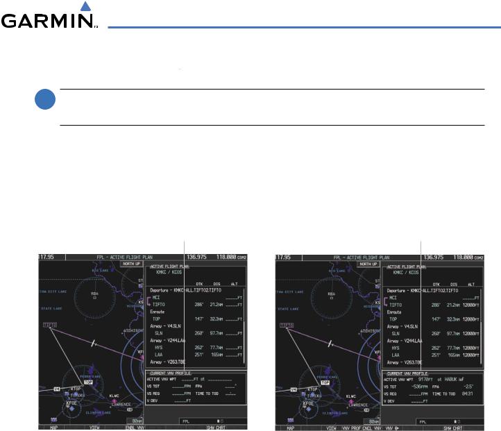
Figure 5-84 Enabling/Disabling Vertical Navigation
Enabling VNV guidance:
1)Press the FPL Key to display the Active Flight Plan Page on the MFD.
2)Press the ENBL VNV Softkey; or press the MENU Key, highlight ‘Enable VNV’, and press the ENT Key. Vertical navigation is enabled,and vertical guidance begins with the waypoint shown in the CURRENTVNV PROFILE box (defaults first waypoint in the active flight plan with an altitude enabled for vertical navigation (e.g., HABUK)).
Disabling VNV guidance:
1)Press the FPL Key to display the Active Flight Plan Page on the MFD.
2)Press the CNCL VNV Softkey; or press the MENU Key, highlight ‘Cancel VNV’, and press the ENT Key. Vertical navigation is disabled.
190-00498-03 Rev.A |
Garmin G1000 Pilot’s Guide for Cessna Nav III |
5-85 |
FLIGHT MANAGEMENT
Canceling vertical navigation results in vertical deviation (V DEV), vertical speed required (VS REQ), and time to top of descent/bottom of descent (TIME TO TOD/BOD) going invalid. The Vertical Deviation Indicator (VDI) and Required Vertical Speed Indication (RVSI) on the PFD are removed, and the V DEV, VS REQ, and TIME TO TOD items displayed in the CURRENT VNV PROFILE box are dashed. VNV remains disabled until manually enabled. Vertical guidance in reversionary mode can only be enabled for a direct-to waypoint.
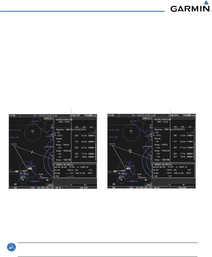
The G1000 allows a vertical navigation direct-to to any waypoint in the active flight plan with an altitude constraint “designated” for vertical guidance. Selecting the VNV Direct-to Softkey on the Active Flight Plan Page allows the flight plan to be flown, while vertical guidance based on the altitude constraint at the VNV direct-to waypoint is provided. The altitude change begins immediately and is spread along the flight plan from current position to the vertical direct-to waypoint, not just along the leg for the direct-to waypoint. A direct-to with altitude constraint activated by pressing the Direct-to Key also provides vertical guidance, but would bypass flight plan waypoints between the current position in the flight plan and the direct-to waypoint. A top of descent (TOD) point is computed based on the default flight path angle; descent begins once the TOD is reached.
Current Vertical Navigation Profile |
Current Vertical Navigation Profile |
Prior to VNV Direct-to |
After VNV Direct-to |
|
|
|
|
|
|
|
|
VNV Direct |
|
|
|
|
|
|
|
-To Softkey |
VNV PROF Softkey |
||||||
Figure 5-85 Vertical Navigation Direct-To
Activating a vertical navigation direct-to:
1)Press the FPL Key to display the Active Flight Plan Page on the MFD.
2)Turn the FMS Knob to highlight the desired waypoint.
NOTE: The selected waypoint must have a designated altitude constraint (light blue number) to be used. If not, the first waypoint in the flight plan with a designated altitude constraint is selected.
3)Press the VNV Direct-To Softkey; or press the MENU Key, highlight ‘VNV Direct-To’, and press the ENT Key. An ‘Activate vertical Direct-to to: NNNNNFT at XXXXXX?’ confirmation window is displayed.
4)Press the ENT Key. Vertical guidance begins to the altitude constraint for the selected waypoint.
5-86 |
Garmin G1000 Pilot’s Guide for Cessna Nav III |
190-00498-03 Rev.A |

FLIGHT MANAGEMENT
The vertical navigation profile can be modified by directly entering a vertical speed target (VS TGT) and/or flight path angle (FPA) in the CURRENT VNV PROFILE box.
Modifying the VS TGT and FPA:
1)Press the FPL Key to display the Active Flight Plan Page on the MFD.
2)Press the VNV PROF Softkey;or press the MENU Key,highlight‘SelectVNV ProfileWindow’,and press the ENT Key.The cursor is now located in the CURRENT VNV PROFILE box without having to scroll all the way through past the end of the active flight plan.
3)Turn the FMS Knobs as needed to edit the values.
ALTITUDE CONSTRAINTS
The G1000 system can use altitude constraints associated with lateral waypoints to give guidance for vertical navigation. These altitudes are, depending on the specific instance, manually entered or retrieved from the published altitudes in the navigation database. The navigation database only contains altitudes for procedures that call for “Cross at” altitudes. If the procedure states “Expect to cross at,” then the altitude is not in the database. In this case the altitude may be entered manually.
Cross AT |
|
|
|
|
Displayed Text |
or ABOVE |
|
|
|
|
Examples |
5,000 ft |
|
|
|
Large White Text |
|
|
|
|
|
||
|
|
|
|
||
Cross AT |
|
|
|
Large Light Blue Text |
|
|
|
|
|||
2,300 ft |
|
|
|
|
|
Cross AT |
|
|
|
|
Small Light Blue Text |
|
|
|
|
||
|
|
|
|
Small Light Blue |
|
or BELOW |
|
|
|
|
|
|
|
|
|
||
3,000 ft |
|
|
|
Subdued Text |
|
Altitude Constraint |
|
|
|
|
Small White Text with |
Examples |
|
|
|
|
|
|
|
|
|
||
|
|
|
|
Altitude Restriction Bar |
|
|
Figure 5-86 Waypoint Altitude Constraints |
||||
190-00498-03 Rev.A |
Garmin G1000 Pilot’s Guide for Cessna Nav III |
5-87 |
FLIGHT MANAGEMENT
|
White Text |
Light Blue Text |
Light Blue Subdued Text |
|
|
|
|
Large |
Altitude calculated by the system |
Altitude has been entered manually. |
The system cannot use this |
Text |
estimating the altitude of the aircraft as |
Altitude is designated for use in giving |
altitude in determining vertical |
|
it passes over the navigation point. This |
vertical speed and deviation guidance. |
speed and deviation guidance |
|
altitude is provided as a reference and is |
Altitude does not match the published |
because of an invalid constraint |
|
not designated to be used in determining |
altitude in navigation database or no |
condition |
|
vertical speed and deviation guidance. |
published altitude exists. |
|
|
|
|
|
Small |
Altitude is not designated to be used in |
Altitude is designated for use in giving |
The system cannot use this |
Text |
determining vertical speed and deviation |
vertical speed and deviation guidance. |
altitude in determining vertical |
|
guidance. Altitude has been retrieved |
Altitude has been retrieved from the |
speed and deviation guidance |
|
from the navigation database and is |
navigation database or has been entered |
because of an invalid constraint |
|
provided as a reference. |
manually and matches a published |
condition |
|
|
altitude in the navigation database. |
|
|
|
|
|
Table 5-8 Altitude Constraint Size and Color Coding
Altitudes associated with approach procedures are “auto-designated”. This means the system automatically uses the altitudes loaded with the approach for giving vertical speed and deviation guidance. Note that these altitudes are displayed as blue text up to, but not including the FAF. The FAF is always a “reference only” altitude and cannot be designated, unless the selected approach does not provide vertical guidance. In this case, the FAF altitude can be designated.
Altitudes that have been designated for use in vertical guidance can be “un-designated” using the CLR Key. The altitude is now displayed only as a reference. It is not used to give vertical guidance. Other displayed altitudes may change due to re-calculations or be rendered invalid as a result of manually changing an altitude to a non-designated altitude.
Designating a waypoint altitude to be used for vertical guidance:
1)Press the FPL Key to display the Active Flight Plan Page on the MFD.
2)Press the FMS Knob, and turn to highlight the desired waypoint altitude.
3)Turn the small FMS Knob to enter editing mode.
4)Press the ENT Key. The altitude is now shown in blue, indicating it is usable for vertical guidance.
Designating a procedure waypoint altitude to be used for vertical guidance:
1)Press the FPL Key to display the Active Flight Plan Page on the MFD.
2)Press the FMS Knob, and turn to highlight the desired waypoint altitude.
3)Press the ENT Key. The altitude is now shown in blue, indicating it is usable for vertical guidance.
Altitude constraints are displayed and entered in feet mean sea level (MSL) values to the nearest hundred. An altitude constraint in feet above ground level (AGL) format is supported for airports. When a database altitude restriction is displayed, the G1000 allows entry of a different altitude when creating a waypoint, effectively overriding the database restriction (only before the FAF). When a database altitude restriction of type “AT or ABOVE” or “AT or BELOW” is activated, the system uses the “AT” portion of the restriction to define the vertical profile.
5-88 |
Garmin G1000 Pilot’s Guide for Cessna Nav III |
190-00498-03 Rev.A |

FLIGHT MANAGEMENT
An altitude constraint is invalid if:
•Meeting the constraint requires the aircraft to climb
•Meeting the constraint requires the maximum flight path angle (6° down) or maximum vertical speed (-6000 fpm) to be exceeded
•The altitude constraint results in a TOD behind the aircraft present position
•The constraint is within a leg type for which altitude constraints are not supported
•The altitude constraint is added to the FAF of an approach that provides vertical guidance (i.e., ILS or GPS WAAS approach)
•The altitude constraint is added to a waypoint past the FAF.
Entering/modifiying an altitude constraint:
1)Press the FPL Key to display the Active Flight Plan Page on the MFD.
2)Press the FMS Knob, and turn to highlight the desired waypoint altitude constraint.
3)Enter an altitude constraint value using the FMS Knobs. To enter altitudes as a flight level, turn the small FMS Knob counter-clockwise past zero or clockwise past 9 on the first character, and the system automatically changes to show units of Flight Level. Turn the large FMS Knob clockwise to highlight the first zero and enter the three digit flight level.
4)Press the ENT Key to accept the altitude constraint; if the selected waypoint is an airport, an additional choice is displayed.Turn the small FMS Knob to choose ‘MSL’ or ‘AGL’, and press the ENT Key to accept the altitude.
Altitude constraints can be modified or deleted after having been added to the flight plan. In the event an altitude constraint is deleted and the navigation database contains an altitude restriction for the lateral waypoint, the G1000 displays the altitude restriction from the database provided no predicted altitude can be provided. The G1000 also provides a way to reinstate a published altitude constraint that has been edited.
Deleting an altitude constraint provided by the navigation database:
1)Press the FPL Key to display the Active Flight Plan Page on the MFD.
2)Press the FMS Knob, and turn to highlight the desired waypoint altitude constraint.
3)Press the CLR Key. A ‘Remove VNV altitude constraint?’ confirmation window is displayed.
4)Select ‘OK’ and press the ENT Key.
Deleting an altitude constraint that has been manually entered:
1)Press the FPL Key to display the Active Flight Plan Page on the MFD.
2)Press the FMS Knob, and turn to highlight the desired waypoint altitude constraint.
3)Press the CLR Key. A ‘Remove or Revert to published VNV altitude of nnnnnFT?’ confirmation window is displayed.
4)Select ‘REMOVE’ and press the ENT Key. The manually entered altitude is deleted (it is replaced by a system calculated altitude, if available).
190-00498-03 Rev.A |
Garmin G1000 Pilot’s Guide for Cessna Nav III |
5-89 |

FLIGHT MANAGEMENT
Reverting a manually entered altitude constraint back to the navigation database value:
1)Press the FPL Key to display the Active Flight Plan Page on the MFD.
2)Press the FMS Knob, and turn to highlight the desired waypoint altitude constraint.
3)Press the CLR Key. A ‘Remove or Revert to published VNV altitude of nnnnnFT?’ confirmation window is displayed.
4)Select ‘REVERT’ and press the ENT Key. The altitude is changed to the navigation database value.
Modifying a system calculated altitude constraint:
1)Press the FPL Key to display the Active Flight Plan Page on the MFD.
2)Press the FMS Knob, and turn to highlight the desired waypoint altitude constraint.
3)Press the CLR Key. An ‘Edit or Revert to published VNV altitude of nnnnnFT?’ confirmation window is displayed.
4)Select ‘EDIT’ and press the ENT Key.
5)Edit the value using the FMS Knobs, and press the ENT Key.
5-90 |
Garmin G1000 Pilot’s Guide for Cessna Nav III |
190-00498-03 Rev.A |