


SYSTEM OVERVIEW
1.6 SYSTEM OPERATION
 NOTE: In normal operating mode, backlighting can only be adjusted from the PFD. In reversionary mode, it can be adjusted from the remaining display.
The displays are connected together via a single Ethernet bus for high-speed communication. Each IAU is connected to a single display, as shown in Figure 1-1. This allows the units to share information, enabling true system integration.. This section discusses normal and reversionary G1000 display operation, as well as the various AHRS modes and G1000 System Annunciations.
NORMAL DISPLAY OPERATION
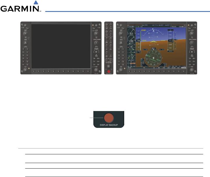
In normal operating mode, the PFD presents graphical flight instrumentation (attitude, heading, airspeed, altitude, vertical speed), replacing the traditional flight instrument cluster (see the Flight Instruments Section for more information).
The MFD normally displays a full-color moving map with navigation information (see the Flight Management Section), while the left portion of the MFD is dedicated to the Engine Indication System (EIS; see the EIS Section).
Both displays offer control for COM and NAV frequency selection.
Figure 1-8 Normal Mode
REVERSIONARY DISPLAY OPERATION
 NOTE: The G1000 System alerts the pilot when backup paths are utilized by the LRUs. Refer to Appendix A for further information regarding system-specific alerts.
In the event of a display failure, the G1000 System automatically switches to reversionary (backup) mode. In reversionary mode, all important flight information is presented on the remaining display in the same format as in normal operating mode.
If a display fails, the appropriate IAU Ethernet interface to the display is cut off. Thus, the IAU can no longer communicate with the remaining display (refer to Figure 1-1), and the NAV and COM functions provided to the failed display by the IAU are flagged as invalid on the remaining display. The system reverts to backup paths for the AHRS, ADC, Engine/Airframe Unit, and Transponder, as required. The change to backup paths is completely automated for all LRUs and no pilot action is required.
1-14 |
Garmin G1000 Pilot’s Guide for Cessna Nav III |
190-00498-03 Rev.A |
SYSTEM OVERVIEW
Figure 1-9 Reversionary Mode (Failed PFD)
If the system fails to detect a display problem, reversionary mode may be manually activated by pressing the Audio Panel’s red DISPLAY BACKUP button (refer to the Audio Panel and CNS Section for further details). Pressing this button again deactivates reversionary mode.
Pressing the DISPLAY BACKUP button activates/deactivates reversionary mode
Figure 1-10 DISPLAY BACKUP Button
AHRS OPERATION
 NOTE: Refer to Appendix A for specific AHRS alert information.
 NOTE: Aggressive maneuvering while AHRS is not operating normally may degrade AHRS accuracy.
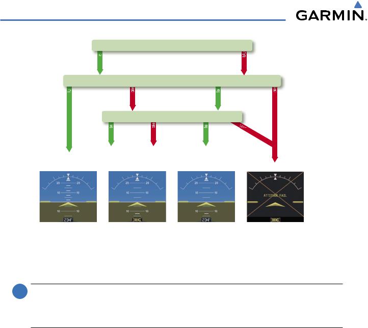
The Attitude and Heading Reference System (AHRS) performs attitude, heading, and vertical acceleration calculations for the G1000 System, utilizing GPS, magnetometer, and air data in addition to information from its internal sensors. Attitude and heading information are updated on the PFD while the AHRS receives appropriate combinations of information from the external sensor inputs.
Loss of GPS, magnetometer, or air data inputs is communicated to the pilot by message advisory alerts. Any failure of the internal AHRS inertial sensors results in loss of attitude and heading information (indicated by red ‘X’ flags over the corresponding flight instruments).
190-00498-03 Rev.A |
Garmin G1000 Pilot’s Guide for Cessna Nav III |
1-15 |
SYSTEM OVERVIEW
GPS
|
availab |
|
|
|
|
|
Magnetometer |
||
availab |
|
unavailab |
availab |
|
|
|
Airspeed Data |
||
|
availab |
unavailab |
availab |
|
AHRS Normal |
AHRS no- |
AHRS no-Mag/ |
AHRS |
|
Mag Mode |
no-Air Mode |
no-GPS |
||
Operation |
||||
Heading Invalid |
Mode |
|||
|
||||
unavailab unavailab
vailable
Attitude/Heading Invalid
Figure 1-11 AHRS Operation
GPS INPUT FAILURE
 NOTE: In-flight initialization of AHRS, when operating without any valid source of GPS data and at true air speed values greater than approximately 200 knots, is not guaranteed. Under these rare conditions, it is possible for in-flight AHRS initialization to take an indefinite amount of time which would result in an extended period of time where valid AHRS outputs are unavailable.
Two GPS inputs are provided to the AHRS. If GPS information from one of the inputs fails, the AHRS uses the remaining GPS input and an alert message is issued to inform the pilot. If both GPS inputs fail, the AHRS can continue to provide attitude and heading information to the PFD as long as magnetometer and airspeed data are available and valid.
MAGNETOMETER FAILURE
If the magnetometer input fails, the AHRS continues to output valid attitude information; however, the heading output on the PFD is flagged as invalid with a red ‘X’.
AIR DATA INPUT FAILURE
Failure of the air data input has no affect on the AHRS output while AHRS is receiving valid GPS information. Invalid/unavailable airspeed data in addition to GPS failure results in loss of all attitude and heading information.
1-16 |
Garmin G1000 Pilot’s Guide for Cessna Nav III |
190-00498-03 Rev.A |
SYSTEM OVERVIEW
G1000 SYSTEM ANNUNCIATIONS
 NOTE: For a detailed description of all annunciations and alerts, refer to Appendix A. Refer to the Pilot’s Operating Handbook (POH) for additional information regarding pilot responses to these annunciations.
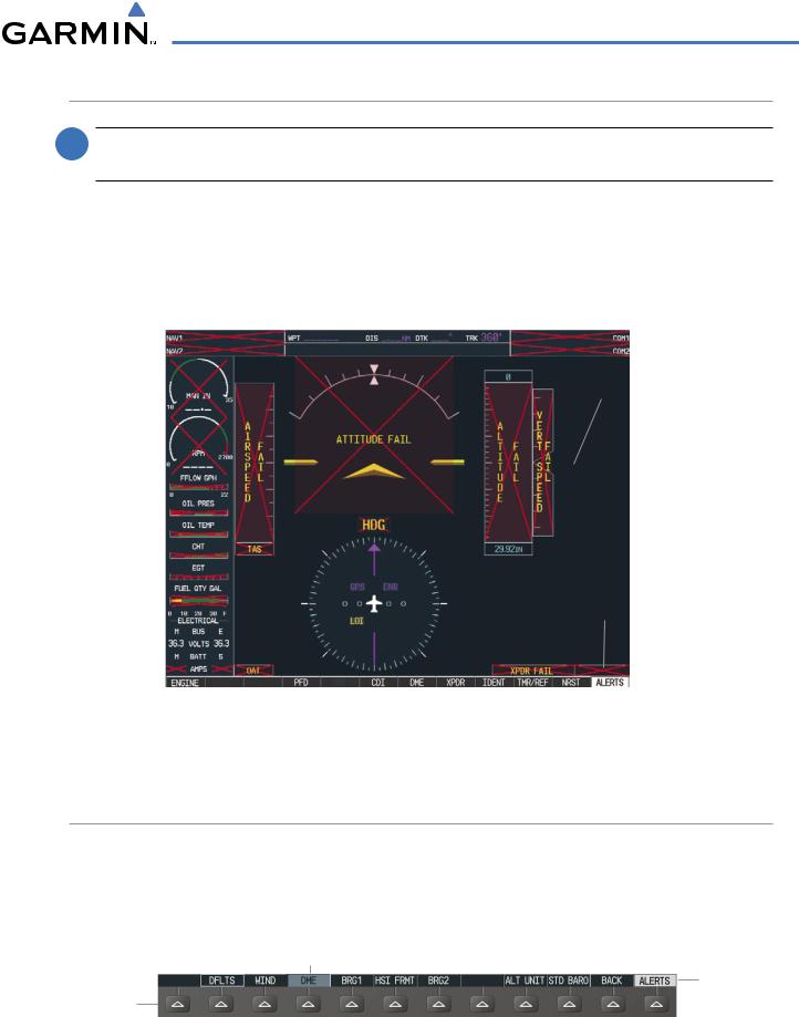
When an LRU or an LRU function fails, a large red “X” is typically displayed on windows associated with the failed data (Figure 1-12 displays all possible flags and responsible LRUs). Upon G1000 power-up, certain windows remain invalid as equipment begins to initialize. All windows should be operational within one minute of power-up. If any window remains flagged, the G1000 system should be serviced by a Garminauthorized repair facility.
GIA 63/W |
|
|
|
|
|
|
|
|
|
|
|
|
|
|
GIA 63/W |
|||||
|
|
|
|
|
|
|
|
|
|
|
|
|||||||||
Integrated |
|
|
|
|
|
|
|
|
|
Integrated |
||||||||||
Avionics Units |
|
|
|
|
|
|
|
|
|
Avionics Units |
||||||||||
|
|
|
|
|
|
|
|
|
|
|
|
|
|
|
|
|
|
|
|
GDC 74A Air |
|
|
|
|
|
|
|
|
|
|
|
|
|
|
|
|
|
|
|
|
|
|
|
|
|
|
|
|
|
|
|
|
|
|
|
|
|
|
|
|
|
Data Computer |
|
|
|
|
|
|
|
|
|
|
|
|
|
|
|
|
|
|
|
|
GRS 77 AHRS |
|
|
|
|
|
|
|
|
|
|
|
|
|
|
|
|
|
|
|
|
|
|
|
|
|
|
|
|
|
|
|
|
|
|
|
|
|
|
|
|
|
|
|
|
|
|
|
|
|
|
|
|
|
|
|
|
|
|
|
|
|
|
|
GEA 71 Engine |
|
|
|
|
|
|
|
|
|
|
|
|
OR |
|||||||
|
|
|
|
|
|
|
|
|
|
|
|
|
|
|
|
|
|
|||
Airframe Unit |
|
|
|
|
|
|
|
|
|
|
|
GMU 44 |
||||||||
OR |
|
|
|
|
|
|
|
|
|
|
|
Magnetometer |
||||||||
GIA 63/W |
|
|
|
|
|
|
|
|
|
|
|
|
|
|
||||||
|
|
|
|
|
|
|
|
|
|
|
|
|||||||||
Integrated |
|
|
|
|
|
|
|
|
|
|
|
|
||||||||
Avionics Unit |
|
|
|
|
|
|
|
|
|
|
|
|
||||||||
|
|
|
|
|
|
|
|
|
|
|
|
|
|
|
|
|
|
|
|
GIA 63/W Integrated |
|
|
|
|
|
|
|
|
|
|
|
|
|
|
|
|
|
|
|
|
|
|
|
|
|
|
|
|
|
|
|
|
|
|
|
|
|
|
|
|
|
Avionics Units |
|
|
|
|
|
|
|
|
|
|
|
|
|
|
|
|
|
|
|
|
GTX 33 Transponder |
|
|
|
|
|
|
|
|
|
|
|
|
|
|
|
|
|
|
|
|
|
|
|
|
|
GDC 74A Air |
|
|
|
|
|
|
|
|
|
|
|
|||||
|
|
|
|
|
|
|
|
|
|
|
|
|
|
|
||||||
|
|
|
|
|
|
|
|
|
|
|
|
|
|
|
||||||
|
|
|
|
|
|
|
|
|
|
|
|
|
|
|
OR |
|||||
|
|
|
|
Data Computer |
|
|
|
|
|
|
|
|
|
|||||||
|
|
|
|
|
|
|
|
|
|
|
|
|
GIA 63/W Integrated |
|||||||
|
|
|
|
|
|
|
|
|
|
|
|
|
|
|
|
|
|
|
|
|
|
|
|
|
|
|
|
|
Figure 1-12 |
G1000 System Failure Annunciations |
Avionics Units |
||||||||||
|
|
|
|
|
|
|
|
|
||||||||||||
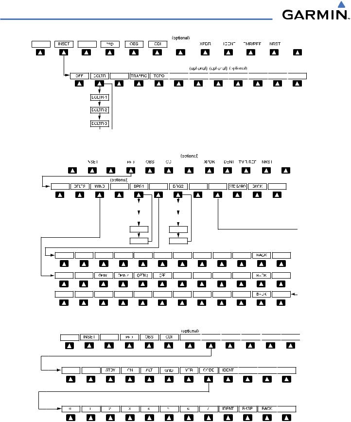
SOFTKEY FUNCTION
The softkeys are located along the bottoms of the displays. The softkeys shown depend on the softkey level or page being displayed. The bezel keys below the softkeys can be used to select the appropriate softkey. When a softkey is selected, its color changes to black text on gray background and remains this way until it is turned off, at which time it reverts to white text on black background.
Softkey
On
Softkey Names
Bezel-Mounted (Displayed)
Softkeys (Press)
Figure 1-13 Softkeys (Second-Level PFD Configuration)
190-00498-03 Rev.A |
Garmin G1000 Pilot’s Guide for Cessna Nav III |
1-17 |

SYSTEM OVERVIEW
PFD SOFTKEYS
The CDI, IDENT, TMR/REF, NRST, and ALERTS softkeys undergo a momentary change to black text on gray background and automatically switch back to white text on black background when selected.
The PFD softkeys provide control over flight management functions, including GPS, NAV, terrain, traffic, and lightning (optional). Each softkey sublevel has a BACK Softkey which can be selected to return to the previous level. The ALERTS Softkey is visible at all softkey levels (label changes if messages are issued).
INSET |
Displays Inset Map in PFD lower left corner |
OFF |
Removes Inset Map |
DCLTR (3) |
Selects desired amount of map detail; cycles through declutter levels: |
|
DCLTR (No Declutter): All map features visible |
|
DCLTR-1: Declutters land data |
|
DCLTR-2: Declutters land and SUA data |
|
DCLTR-3: Removes everything except for the active flight plan |
TRAFFIC |
Displays traffic information on Inset Map |
TOPO |
Displays topographical data (e.g., coastlines, terrain, rivers, lakes) and |
|
elevation scale on Inset Map |
TERRAIN |
Displays terrain information on Inset Map |
STRMSCP |
Displays Stormscope® information on Inset Map |
NEXRAD |
Displays NEXRAD weather and coverage information on Inset Map (optional |
|
feature) |
XM LTNG |
Displays XM lightning information on Inset Map (optional feature) |
PFD |
Displays second-level softkeys for additional PFD configurations |
DFLTS |
Resets PFD to default settings, including changing units to standard |
WIND |
Displays softkeys to select wind data parameters |
OPTN 1 |
Wind direction arrows with headwind and crosswind components |
OPTN 2 |
Wind direction arrow and speed |
OPTN 3 |
Wind direction arrow with direction and speed |
OFF |
Information not displayed |
DME |
Displays the DME Information Window |
BRG1 |
Cycles the Bearing 1 Information Window through NAV1, GPS/ waypoint |
|
identifier and GPS-derived distance information, and ADF/frequency |
HSI FRMT |
Provides access to the HSI formatting softkeys |
360 HSI |
Displays the HSI in a 360 degree view |
ARC HSI |
Displays the HSI as an arc |
BRG2 |
Cycles the Bearing 2 Information Window through NAV2 or GPS waypoint |
|
identifier and GPS-derived distance information, and ADF/frequency. |
1-18 |
Garmin G1000 Pilot’s Guide for Cessna Nav III |
190-00498-03 Rev.A |
SYSTEM OVERVIEW
ALT UNIT |
Displays softkeys for setting the altimeter and BARO settings to |
||||||||||||||||
|
|
|
|
metric units |
|||||||||||||
|
|
METERS |
When enabled, displays altimeter in meters |
||||||||||||||
|
|
IN |
Press to display the BARO setting as inches of mercury |
||||||||||||||
|
|
HPA |
Press to display the BARO setting as hectopacals |
||||||||||||||
STD BARO |
Sets barometric pressure to 29.92 in Hg (1013 hPa if METRIC softkey is |
||||||||||||||||
|
|
|
|
selected) |
|||||||||||||
OBS |
Selects OBS mode on the CDI when navigating by GPS (only available with |
||||||||||||||||
|
|
|
|
active leg) |
|||||||||||||
CDI |
Cycles through GPS, VOR1, and VOR2 navigation modes on the CDI |
||||||||||||||||
DME |
Displays the DME Tuning Window, allowing selection of the DME |
||||||||||||||||
XPDR |
Displays transponder mode selection softkeys |
||||||||||||||||
STBY |
Selects standby mode (transponder does not reply to any interrogations) |
||||||||||||||||
ON |
Selects Mode A (transponder replies to interrogations) |
||||||||||||||||
ALT |
SelectsModeC–altitudereportingmode(transponderrepliestoidentification |
||||||||||||||||
|
|
|
|
and altitude interrogations) |
|||||||||||||
GND |
Allows manual selection of ground mode in certain conditions |
||||||||||||||||
VFR |
Automatically enters the VFR code (1200 in the U.S.A. only) |
||||||||||||||||
CODE |
Displays transponder code selection softkeys 0-7 |
||||||||||||||||
|
|
0 — 7 |
Use numbers to enter code |
||||||||||||||
IDENT |
Activates the Special Position Identification (SPI) pulse for 18 seconds, |
||||||||||||||||
|
|
|
|
identifying the transponder return on the ATC screen |
|||||||||||||
BKSP |
Removes numbers entered, one at a time |
||||||||||||||||
IDENT |
Activates the Special Position Identification (SPI) pulse for 18 seconds, |
||||||||||||||||
|
|
|
|
identifying the transponder return on the ATC screen |
|||||||||||||
TMR/REF |
Displays Timer/References Window |
||||||||||||||||
NRST |
Displays Nearest Airports Window |
||||||||||||||||
ALERTS |
Displays Alerts Window |
||||||||||||||||
|
|
|
|
|
|
|
|
|
|
|
|
|
|
|
|
|
|
|
|
|
|
|
|
|
|
|
|
|
|
|
|
|
|
|
|
|
|
|
|
|
|
|
|
|
|
|
|
|
|
|
|
|
|
|
|
|
|
|
|
|
|
|
|
|
|
|
|
|
|
|
|
|
|
|
|
|
|
|
|
|
|
|
|
|
|
|
|
|
|
|
|
|
|
|
|
|
|
|
|
|
|
|
|
|
|
|
|
|
|
|
|
|
|
|
|
|
|
|
|
|
|
|
|
|
|
|
|
|
|
|
|
|
|
|
|
|
|
|
|
|
|
|
|
|
|
|
|
|
|
|
|
|
|
|
|
|
|
|
|
|
|
|
|
|
|
|
|
|
|
|
|
|
|
|
|
|
|
|
|
|
|
|
|
|
|
|
|
|
|
|
|
|
|
|
|
|
|
|
|
|
|
|
|
|
|
|
|
|
|
|
|
|
|
|
|
|
|
|
|
|
|
|
|
|
|
|
|
|
|
|
|
|
|
|
|
|
|
|
|
|
|
|
|
|
|
|
|
|
|
|
|
|
|
|
|
|
|
|
|
|
|
|
|
|
|
|
|
|
|
|
|
|
|
|
|
|
|
|
|
|
|
|
|
|
|
|
|
Figure 1-14 Top Level PFD Softkeys
190-00498-03 Rev.A |
Garmin G1000 Pilot’s Guide for Cessna Nav III |
1-19 |
SYSTEM OVERVIEW
DME |
|
|
|
|
|
|
|
|
|
ALERTS |


 STRMSCP


 ALERTS
Press the BACK or OFF Softkey to return to the top-level softkeys.
Figure 1-15 INSET Softkeys
|
|
|
|
|
|
DME |
|
|
|
|
ALERTS |
DME |
HSI FRMT |
ALT UNIT |
ALERTS |
BRG1(NAV1) |
|
BRG2(NAV2) |
Press the STD BARO or |
||
|
|
|
|
|
|
|
|
|
|
|
|
|
|
|
|
|
BACK Softkey to return to |
BRG1(GPS) |
|
BRG2(GPS) |
|||
|
|
|
|
|
the top-level softkeys |
|
|
|
|
|
|
BRG1(ADF) |
|
BRG2(ADF) |
|
|
BRG1(OFF) |
|
BRG2(OFF) |
|
|
|
360 HSI |
ARC HSI |
|
ALERTS |
|
|
|
|
ALERTS |
|
METERS |
IN |
HPA |
ALERTS |
Figure 1-16 |
PFD Configuration Softkeys |
|
|
|
DME 


 ALERTS


 ALERTS
Press the BACK Softkey to return to the top-level softkeys.

 ALERTS
Press the IDENT or BACK Softkey to return to the top-level softkeys.
Figure 1-17 XPDR (Transponder) Softkeys
1-20 |
Garmin G1000 Pilot’s Guide for Cessna Nav III |
190-00498-03 Rev.A |

SYSTEM OVERVIEW
MFD SOFTKEYS
ENGINE |
PressingthissoftkeymakesavailabletheLEANandSYSTEM |
|
Softkeys |
LEAN |
Pressing makes available the CYL SLCT and ASSIST |
|
Softkeys to facilitate engine leaning |
CYL SLCT |
The Cylinder Select Softkey cycles through selection of each |
|
cylinder indicated by changing the cylinder display to light |
|
blue |
ASSIST |
Pressing the ASSIST Softkey causes the first cylinder that |
|
peaks to become highlighted and information for that |
|
cylinder to be displayed |
BACK |
Returns to the previous level softkeys |
SYSTEM |
Press this softkey to make available the RST FUEL and GAL |
|
REM Softkeys |
RST FUEL |
Pressing the Rest Fuel Softkey resets fuel used and gallons |
|
remaining to zero |
GAL REM |
Press this softkey (Gallons Remaining) to display the quantity |
|
adjustment softkeys |
|
-10 GAL Pressing decreases the fuel remaining quantity in 10 gallon |
|
increments |
|
-1 GAL Pressing decreases the fuel remaining quantity in 1 gallon |
|
increments |
|
+1GAL Pressing increases the fuel remaining quantity in 10 gallon |
|
increments |
|
+10 GAL Pressing decreases the fuel remaining quantity in 10 gallon |
|
increments |
|
XX GAL Pressing this softkey sets the fuel remaining to the quantity |
|
at the filler neck tab where XX is an airframe specific |
|
quantity |
|
XX GAL Pressing this softkey sets the fuel remaining to the full tank |
|
quantity where XX as an airframe specific quantity |
MAP |
Enables second-level Navigation Map softkeys |
TRAFFIC |
Displays traffic information on Navigation Map |
TOPO |
Displays topographical data (e.g., coastlines, terrain, rivers, |
|
lakes) and elevation scale on Navigation Map |
TERRAIN |
Displays terrain information on Navigation Map |
AIRWAYS |
Displays airways on the map; cycles through the |
(Default label |
following: |
is dependant |
AIRWAYS: No airways are displayed |
on map |
AIRWY ON: All airways are displayed |
setup option |
AIRWY LO: Only low altitude airways are displayed |
selected) |
AIRWY HI: Only high altitude airways are displayed |
190-00498-03 Rev.A |
Garmin G1000 Pilot’s Guide for Cessna Nav III |
1-21 |

SYSTEM OVERVIEW
STRMSCP |
Pressing this softkey displays/removes Stormscope lightning |
|
data on the Navigation Map. |
NEXRAD |
Displays NEXRAD weather and coverage information on |
|
Navigation Map (optional feature) |
XM LTNG |
Displays XM lightning information on Navigation Map |
|
(optional feature) |
BACK |
Returns to top-level softkeys |
DCLTR (3) |
Selectsdesiredamountofmapdetail;cyclesthroughdeclutter |
|
levels: |
|
DCLTR (No Declutter): All map features visible |
|
DCLTR-1: Declutters land data |
|
DCLTR-2: Declutters land and SUA data |
|
DCLTR-3: Removes everything except for the active flight |
|
plan |
SHW CHRT |
Displays the appropriate chart |
CHKLIST |
Displays the Checklist Page |
ENGINE |
Displays the engine checklist |
DONE |
Pressing this softkey checks off a checklist item. If an item is |
|
already checked, an UNDO Softkey is displayed. |
EXIT |
Press to exit the checklist |
EMERGCY |
Displays the emergency checklist |
1-22 |
Garmin G1000 Pilot’s Guide for Cessna Nav III |
190-00498-03 Rev.A |