

FLIGHT INSTRUMENTS
2.2 SUPPLEMENTAL FLIGHT DATA
 NOTE: Pressing the DFLTS Softkey (a second-level PFD softkey) turns off metric Altimeter display, the Inset Map, and wind data.
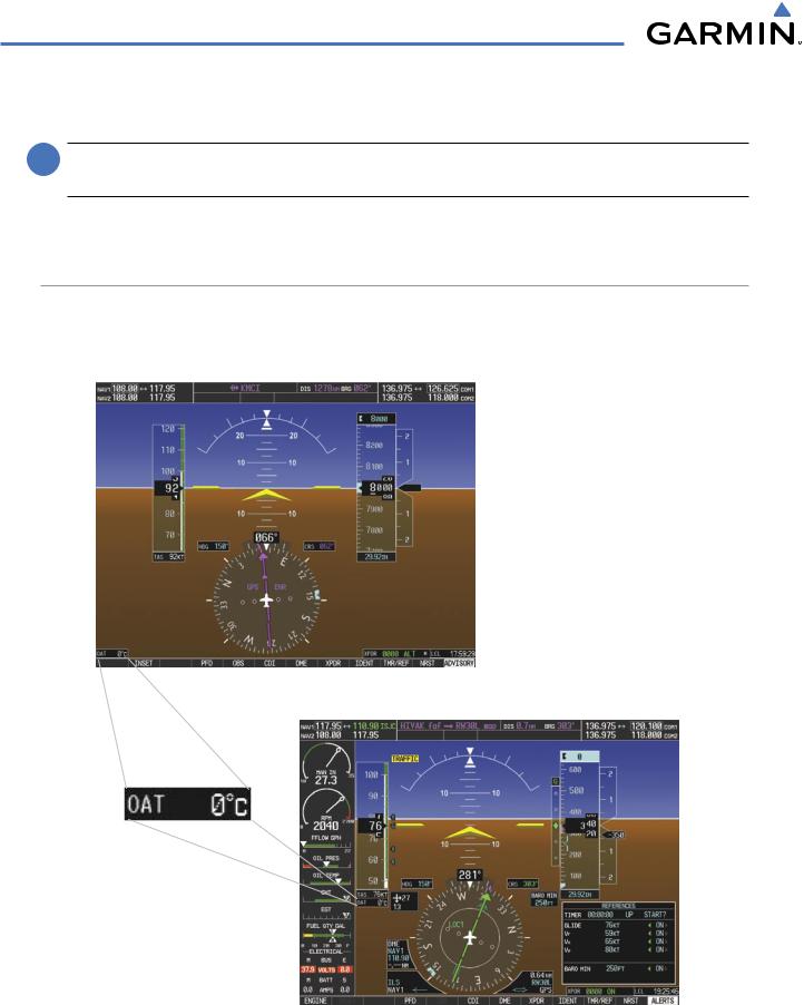
In addition to the flight instruments, the PFD also displays various supplemental information, including the Outside Air Temperature (OAT), wind data, and Vertical Navigation (VNV) indications.
OUTSIDE AIR TEMPERATURE
The Outside Air Temperature (OAT) is displayed in degrees Celsius (°C) by default in the lower left of the PFD under normal display conditions, or below the true airspeed in reversionary mode.
Normal Display
Reversionary Mode
Figure 2-30 Outside Air Temperature
2-22 |
Garmin G1000 Pilot’s Guide for Cessna Nav III |
190-00498-03 Rev.A |
FLIGHT INSTRUMENTS
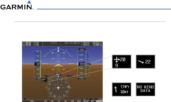
WIND DATA
Wind direction and speed (relative to the aircraft) in knots can be displayed in a window to the upper left of the HSI. When the window is selected for display, but wind information is invalid or unavailable, the window shows “NO WIND DATA”. Wind data can be displayed in three different ways:
Option 1 |
Option 2 |
Option 3 |
No Data |
Figure 2-31 Wind Data
Displaying wind data:
1)Press the PFD Softkey.
2)Press the WIND Softkey to display wind data below the Selected Heading.
3)Press one of the OPTN softkeys to change how wind data is displayed.
•OPTN 1:Wind direction arrows with headwind and crosswind components
•OPTN 2:Wind direction arrow and speed
•OPTN 3:Wind direction arrow with direction and speed
4)To remove the window, press the OFF Softkey.
190-00498-03 Rev.A |
Garmin G1000 Pilot’s Guide for Cessna Nav III |
2-23 |
FLIGHT INSTRUMENTS
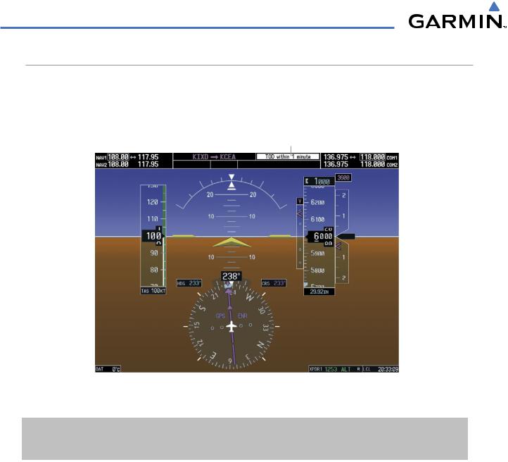
VERTICAL NAVIGATION (VNV) INDICATIONS
When a VNV flight plan has been activated, VNV indications (VNV Target Altitude, RVSI, VDI) appear on the PFD in conjunction with the “TOD within 1 minute” message and “Vertical track” voice alert. See the Flight Management section for details on VNV features. VNV indications are removed from the PFD according to the criteria listed in Table 2-2.
Top of Descent Message
|
|
|
|
|
|
VNV Target |
|
|
|
|
|
|
|
|
Altitude |
|
|
|
|
|
|
|
|
|
|
|
|
|
|
|
Vertical |
|
|
|
|
|
|
|
Deviation |
|
|
|
|
|
|
|
|
|
|
|
|
|
|
|
Indicator |
|
|
|
|
|
|
|
Required |
|
|
|
|
|
|
|
Vertical |
|
|
|
|
|
|
|
|
|
|
|
|
|
|
|
|
|
|
|
|
|
|
Speed Bug |
|
GPS is |
|
|
|
Enroute |
|||
Selected |
|
|
|
|
|
|
|
|
|
|
Phase of |
||||
Navigation |
|
|
|
||||
|
|
|
Flight |
||||
Source |
|
|
|
||||
|
|
|
|
||||
Figure 2-32 Vertical Navigation Indications (PFD)
|
VNV Indication Removed |
|
||
Criteria |
Required Vertical |
Vertical |
|
VNV Target |
|
Speed (RVSI) |
Deviation (VDI) |
|
Altitude* |
Aircraft > 1 min before the next TOD and not on a descent leg |
X |
X |
|
X |
Aircraft > 1 min before the next TOD due to flight plan change |
X |
X |
|
X |
VNV cancelled (CNCL VNV Softkey pressed on MFD) |
X |
X |
|
X |
Distance to active waypoint cannot be computed due to |
|
|
|
|
unsupported flight plan leg type (see the Flight Management |
X |
X |
|
X |
Section) |
|
|
|
|
Aircraft > 250 feet below active VNV Target Altitude |
X |
X |
|
X |
Current crosstrack or track angle error has exceeded limit |
X |
X |
|
X |
Active altitude-constrained waypoint can not be reached within |
X |
X |
|
|
maximum allowed flight path angle and vertical speed |
|
|
||
|
|
|
|
|
Last altitude-constrained waypoint in active flight plan reached |
X |
X |
|
X |
(30 sec before) |
|
|||
|
|
|
|
|
Table 2-2 VNV Indication Removal Criteria |
|
|
|
|
2-24 |
Garmin G1000 Pilot’s Guide for Cessna Nav III |
190-00498-03 Rev.A |